EP4397259A2 - Tandemstangenverbinder und zugehörige verfahren - Google Patents
Tandemstangenverbinder und zugehörige verfahren Download PDFInfo
- Publication number
- EP4397259A2 EP4397259A2 EP24176474.5A EP24176474A EP4397259A2 EP 4397259 A2 EP4397259 A2 EP 4397259A2 EP 24176474 A EP24176474 A EP 24176474A EP 4397259 A2 EP4397259 A2 EP 4397259A2
- Authority
- EP
- European Patent Office
- Prior art keywords
- connector
- rod
- assembly
- locking nut
- receiver member
- Prior art date
- Legal status (The legal status is an assumption and is not a legal conclusion. Google has not performed a legal analysis and makes no representation as to the accuracy of the status listed.)
- Granted
Links
Images









Classifications
-
- A—HUMAN NECESSITIES
- A61—MEDICAL OR VETERINARY SCIENCE; HYGIENE
- A61B—DIAGNOSIS; SURGERY; IDENTIFICATION
- A61B17/00—Surgical instruments, devices or methods
- A61B17/56—Surgical instruments or methods for treatment of bones or joints; Devices specially adapted therefor
- A61B17/58—Surgical instruments or methods for treatment of bones or joints; Devices specially adapted therefor for osteosynthesis, e.g. bone plates, screws or setting implements
- A61B17/68—Internal fixation devices, including fasteners and spinal fixators, even if a part thereof projects from the skin
- A61B17/70—Spinal positioners or stabilisers, e.g. stabilisers comprising fluid filler in an implant
- A61B17/7049—Connectors, not bearing on the vertebrae, for linking longitudinal elements together
-
- A—HUMAN NECESSITIES
- A61—MEDICAL OR VETERINARY SCIENCE; HYGIENE
- A61B—DIAGNOSIS; SURGERY; IDENTIFICATION
- A61B17/00—Surgical instruments, devices or methods
- A61B17/56—Surgical instruments or methods for treatment of bones or joints; Devices specially adapted therefor
- A61B17/58—Surgical instruments or methods for treatment of bones or joints; Devices specially adapted therefor for osteosynthesis, e.g. bone plates, screws or setting implements
- A61B17/68—Internal fixation devices, including fasteners and spinal fixators, even if a part thereof projects from the skin
- A61B17/70—Spinal positioners or stabilisers, e.g. stabilisers comprising fluid filler in an implant
- A61B17/7001—Screws or hooks combined with longitudinal elements which do not contact vertebrae
-
- A—HUMAN NECESSITIES
- A61—MEDICAL OR VETERINARY SCIENCE; HYGIENE
- A61B—DIAGNOSIS; SURGERY; IDENTIFICATION
- A61B17/00—Surgical instruments, devices or methods
- A61B17/56—Surgical instruments or methods for treatment of bones or joints; Devices specially adapted therefor
- A61B17/58—Surgical instruments or methods for treatment of bones or joints; Devices specially adapted therefor for osteosynthesis, e.g. bone plates, screws or setting implements
- A61B17/68—Internal fixation devices, including fasteners and spinal fixators, even if a part thereof projects from the skin
- A61B17/70—Spinal positioners or stabilisers, e.g. stabilisers comprising fluid filler in an implant
- A61B17/7001—Screws or hooks combined with longitudinal elements which do not contact vertebrae
- A61B17/7032—Screws or hooks with U-shaped head or back through which longitudinal rods pass
-
- A—HUMAN NECESSITIES
- A61—MEDICAL OR VETERINARY SCIENCE; HYGIENE
- A61B—DIAGNOSIS; SURGERY; IDENTIFICATION
- A61B17/00—Surgical instruments, devices or methods
- A61B17/56—Surgical instruments or methods for treatment of bones or joints; Devices specially adapted therefor
- A61B17/58—Surgical instruments or methods for treatment of bones or joints; Devices specially adapted therefor for osteosynthesis, e.g. bone plates, screws or setting implements
- A61B17/68—Internal fixation devices, including fasteners and spinal fixators, even if a part thereof projects from the skin
- A61B17/84—Fasteners therefor or fasteners being internal fixation devices
- A61B17/86—Pins or screws or threaded wires; nuts therefor
- A61B17/8605—Heads, i.e. proximal ends projecting from bone
-
- A—HUMAN NECESSITIES
- A61—MEDICAL OR VETERINARY SCIENCE; HYGIENE
- A61B—DIAGNOSIS; SURGERY; IDENTIFICATION
- A61B17/00—Surgical instruments, devices or methods
- A61B17/56—Surgical instruments or methods for treatment of bones or joints; Devices specially adapted therefor
- A61B17/58—Surgical instruments or methods for treatment of bones or joints; Devices specially adapted therefor for osteosynthesis, e.g. bone plates, screws or setting implements
- A61B17/68—Internal fixation devices, including fasteners and spinal fixators, even if a part thereof projects from the skin
- A61B17/84—Fasteners therefor or fasteners being internal fixation devices
- A61B17/86—Pins or screws or threaded wires; nuts therefor
- A61B17/866—Material or manufacture
-
- A—HUMAN NECESSITIES
- A61—MEDICAL OR VETERINARY SCIENCE; HYGIENE
- A61B—DIAGNOSIS; SURGERY; IDENTIFICATION
- A61B17/00—Surgical instruments, devices or methods
- A61B17/56—Surgical instruments or methods for treatment of bones or joints; Devices specially adapted therefor
- A61B17/58—Surgical instruments or methods for treatment of bones or joints; Devices specially adapted therefor for osteosynthesis, e.g. bone plates, screws or setting implements
- A61B17/68—Internal fixation devices, including fasteners and spinal fixators, even if a part thereof projects from the skin
- A61B17/84—Fasteners therefor or fasteners being internal fixation devices
- A61B17/86—Pins or screws or threaded wires; nuts therefor
- A61B17/8685—Pins or screws or threaded wires; nuts therefor comprising multiple separate parts
Definitions
- Orthopedic devices and methods are disclosed herein, including tandem rod connectors and related methods.
- Fixation systems can be used in orthopedic surgery to align and/or fix a desired relationship between two or more bones or bone fragments.
- spinal fixation systems can be used to align and/or fix a desired relationship between vertebrae.
- a typical spinal fixation system can include bone screws or other anchors implanted in the vertebrae and connected by longitudinal rods.
- rods might be arranged in tandem when adding a rod to an existing construct to extend the construct to additional vertebral levels, or when seeking to achieve a rod offset to clear other implants or patient anatomy, or to better fit with a series of implanted bone anchors.
- rods might be arranged in tandem when adding a rod to an existing construct to extend the construct to additional vertebral levels, or when seeking to achieve a rod offset to clear other implants or patient anatomy, or to better fit with a series of implanted bone anchors.
- it can be desirable or necessary to attach multiple rods to the same bone anchor This can arise, for example, when insufficient space or poor bone quality prevents use of a separate bone anchor at a particular location, or prevents use of a connector that attaches directly to both rods.
- Existing solutions for attaching multiple rods may be bulky, may require a large offset between the rods, or may limit the flexibility with which one rod can be positioned relative to another.
- Connectors are disclosed herein that can be used to attach a rod to a bone anchor assembly that is already occupied by a separate rod.
- Various ways of attaching the connector to the bone anchor assembly are disclosed, including arrangements in which the connector is locked to the bone anchor, arrangements in which the connector is constrained in one or more degrees of freedom relative to the bone anchor, arrangements in which the connector is adjustable in one or more degrees of freedom relative to the bone anchor, and arrangements that include a spherical articulation joint.
- attachment of the connector to a bone anchor can be aided with the use of a positioner.
- a connector assembly can include a connector having a proximal end and a distal end that define a proximal-distal axis, the connector including: a first portion configured to mate the connector to a receiver member of a bone anchor assembly, the bone anchor assembly having a first rod-receiving recess for receiving a first rod, and a second portion in which a second rod-receiving recess is formed, the second rod-receiving recess being configured to receive a second rod; a first fastener having a distal portion configured to engage the receiver member to lock the first rod to the receiver member and a proximal portion that extends through an opening formed in the first portion of the connector; a nut mateable to the first fastener to secure the connector to the receiver member; and a second fastener engaged with the second portion of the connector to lock the second rod to the connector; wherein the second rod-receiving recess includes a proximal opening and
- the first and second rods can have a rod diameter
- the first and second rods can have a center-to-center offset, when seated in the receiver member and the connector, respectively, and a ratio of the center-to-center offset to rod diameter can be in the range of about 2:1 to about 4: 1.
- the ratio of the center-to-center offset to rod diameter can be about 2:1.
- the first and second rods can have a center-to-center offset, when seated in the receiver member and the connector, respectively, in the range of about 6 mm to about 16 mm, e.g., in the range of about 6 mm to about 10 mm.
- the first and second rods can have a center-to-center offset, when seated in the receiver member and the connector, respectively, of about 8 mm.
- the first rod-receiving recess can include a first rod seat and the first rod seat can be distal to the seat of the second rod-receiving recess.
- the first rod-receiving recess can include a first rod seat and the first rod seat can be proximal to the seat of the second rod-receiving recess.
- the first rod-receiving recess can include a first rod seat and the first rod seat can be at substantially the same proximal-distal height as the seat of the second rod-receiving recess.
- the first portion of the connector can include a recess configured to receive a proximal end of the receiver member, the recess being cylindrical such that, when the receiver member is received in the recess, the receiver member is free to rotate relative to the connector about a central axis of the receiver member.
- the first portion of the connector can include a recess configured to receive a proximal end of the receiver member, the recess including one or more flats that abut corresponding flats of the receiver member such that, when the receiver member is received in the recess, the receiver member is constrained to uniplanar motion relative to the connector.
- the first portion of the connector can include a recess configured to receive a proximal end of the receiver member, the recess forming a substantial negative of the receiver member such that, when the receiver member is received in the recess, the receiver member cannot rotate or translate relative to the connector.
- the first portion of the connector can include a domed distal-facing surface that bears against a proximal-facing surface of the receiver member in a gimbal interface.
- the opening in the first portion of the connector can be oversized relative to the first fastener to allow movement of the connector relative to the receiver member.
- the assembly can include a positioner having a central opening in which the first fastener is received and distally-extending tabs that engage the receiver member to limit rotation between the positioner and the receiver member.
- the positioner can include teeth configured to be selectively enmeshed with teeth of the connector to limit rotation between the connector and the receiver member.
- the positioner can include a flat formed on an outer sidewall of the positioner and configured to selectively engage a flat formed on an inner sidewall of the connector to limit rotation between the connector and the receiver member. Tightening the nut can be effective to clamp the tabs of the positioner onto the first fastener.
- the nut can have a spherical exterior surface received within a spherical interior surface of the opening formed in the first portion of the connector to allow the connector to move polyaxially relative to the receiver member.
- the nut can include a conical distal-facing surface that contacts a conical proximal-facing surface of the connector.
- the conical surfaces of the nut and the connector can taper at angles that differ from one another.
- the conical surfaces of the nut and the connector can taper at the same angle.
- the nut can be a locking nut configured to expand within the opening to lock an orientation of the connector relative to the receiver member.
- At least one of the first fastener and a throughbore of the locking nut can have a tapered thread such that rotation of the locking nut relative to the first fastener is effective to radially expand the locking nut.
- the locking nut can have a castle drive feature with curved abutment surfaces.
- a distal surface of the connector can be configured to constrain movement of the connector relative to the receiver member to a direction parallel to the first rod.
- a distal surface of the connector can be configured to constrain movement of the connector relative to the receiver member to a direction perpendicular to the first rod.
- the second rod can be positionable in the second rod-receiving recess by moving the second rod distally relative to the connector.
- the second rod-receiving recess can follow a curved path between the proximal opening and the distal seat.
- a connector assembly can include a connector that includes an opening that defines a spherical interior surface and a rod-receiving recess laterally offset from the opening and configured to receive an elongate spinal rod; a threaded fastener; and a locking nut received within the opening of the connector, the locking nut having a spherical exterior surface and a threaded throughbore in which a proximal end of the fastener is received; wherein the assembly has an unlocked configuration in which the connector is polyaxially movable relative to the fastener and a locked configuration in which an orientation of the connector relative to the fastener is fixed, the locking nut being radially expanded in the locked configuration as compared to the unlocked configuration.
- the threads of the fastener or the threads of the locking nut can be tapered such that rotation of the locking nut relative to the fastener is effective to radially expand the locking nut.
- the locking nut can have a castle drive feature with curved abutment surfaces.
- a distal surface of the connector can include a first planar portion and a second planar portion oriented at an oblique angle with respect to the first planar portion to constrain movement of the connector relative to a receiver member in which the set screw is disposed.
- a spinal fixation method can include implanting a bone anchor assembly in a vertebra of a patient, the bone anchor assembly including a receiver member having a first rod-receiving recess; inserting a first rod into the first rod-receiving recess of the receiver member; inserting a first fastener into the receiver member to secure the first rod in the receiver member; positioning a connector over the receiver member such that a proximal portion of the first fastener extends through an opening formed in the connector; inserting a second rod into a second rod-receiving recess formed in the connector; inserting a second fastener into a fastener recess formed in the connector to secure the second rod in the connector; adjusting an orientation of the connector relative to the receiver member to achieve a desired positioning of the first and second rods; and tightening a nut on the first fastener to fix the orientation of the connector relative to the receiver member.
- the method can include positioning the first and second rods such that a center-to-center offset between the first and second rods is in the range of about 6 mm to about 16 mm, e.g., in the range of about 6 mm to about 10 mm.
- the method can include positioning the first and second rods such that a ratio of a center-to-center offset, between the first and second rods, to a diameter of the first and second rods is in the range of about 2:1 to about 4:1.
- the method can include positioning the first and second rods such that a ratio of a center-to-center offset, between the first and second rods, to a diameter of the first and second rods is about 2:1.
- the method can include placing a positioner between the connector and the receiver member, wherein the positioner restricts relative rotation between the connector and the receiver member about the first fastener after the nut is tightened.
- the method can include positioning the first and second rods such that the first rod is anterior to the second rod.
- the method can include positioning the first and second rods such that the first and second rods substantially lie in a common coronal plane. Inserting the second rod can include moving the rod distally and laterally within a curved rod-receiving recess. Inserting the second rod can include moving the rod distally and laterally within an obliquely angled rod-receiving recess. Inserting the second rod can include top loading the rod into the connector. Adjusting the orientation can include pivoting the connector about at least one of a uniplanar interface, a gimbal interface, and a spherical articulation joint.
- Connectors are disclosed herein that can be used to attach a rod to a bone anchor assembly that is already occupied by a separate rod.
- Various ways of attaching the connector to the bone anchor assembly are disclosed, including arrangements in which the connector is locked to the bone anchor, arrangements in which the connector is constrained in one or more degrees of freedom relative to the bone anchor, arrangements in which the connector is adjustable in one or more degrees of freedom relative to the bone anchor, and arrangements that include a spherical articulation joint.
- attachment of the connector to a bone anchor can be aided with the use of a positioner.
- the geometry of the connector can be selected to minimize the offset between a first rod received in the bone anchor assembly and a second rod received in the connector, for example using an angled or curved rod recess and/or a fastener, or set screw, that is offset from the center of the rod or angled relative to the bone anchor.
- the connector can be configured to align the first and second rods in a common coronal plane, or can be configured to position one rod more anterior or posterior than the other rod.
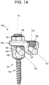
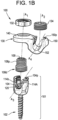
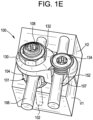
- FIGS. 1A-1E illustrate an exemplary embodiment of a connector assembly 100 which can be used, for example, to connect a second spinal rod 107 to a bone anchor assembly 101 in which a first spinal rod 106 is received.
- the connector assembly 100 can include a connector 130 having a first portion 140 for mating the connector with a bone anchor assembly 101 and a second portion 150 for mating the connector with a fixation element such as the illustrated rod 107.
- the first portion 140 of the connector 130 can receive, fit over, or otherwise interact with a proximal portion 104p of a head or receiver member 104 of the bone anchor assembly 101.
- a second fastener, set screw or other closure mechanism, 134 can be secured within a proximal opening 156 of the second portion 150 of the connector 130 to lock a spinal rod 107 therein. While first and second set screws are shown, other fasteners can be used instead or in addition, such as quarter-turn closure caps, nuts, etc.
- the illustrated bone anchor assembly 101 generally includes a proximal head or receiver member 104 and a threaded distal shank or bone anchor 102.
- the bone anchor 102 can be formed integrally with the receiver member 104 or can be a separate component movably coupled to the receiver member. In the latter configuration, the bone anchor 102 can be selectively locked in any of a variety of orientations relative to the receiver member 104.
- the bone anchor 102 can be polyaxially movable relative to the receiver member 104 within a cone of angulation generally defined by the geometry of the distal end of the receiver member and the proximal head of the bone anchor.
- the bone anchor assembly 101 can be locked to maintain the bone anchor 102 at fixed orientation relative to the receiver member 104.
- the bone anchor assembly 101 can be a favored angle screw, a conventional (non-biased) polyaxial screw, a monoaxial screw, a uniplanar screw, a hook, or any of a variety of other bone anchor types known in the art.
- the first fixation element or rod 106 can be received within the receiver member 104.
- the first rod 106 can directly contact the proximal head of the bone anchor 102 or can contact an intermediate element such as a compression cap or collet (not shown).
- a compression member can be positioned within the receiver member 104 and interposed between the spinal rod 106 and the proximal head of the bone anchor 102 to compress the distal outer surface of the proximal head into direct, fixed engagement with the distal inner surface of the receiver member 104.
- the receiver member 104 can include a central longitudinal or proximal-distal axis A1.
- the receiver member 104 can include a pair of spaced apart arms 114A, 114B that define a first rod-receiving recess or channel 120 for receiving the spinal rod 106.
- the channel 120 can be U-shaped as shown or can have various other configurations.
- a rod 106 seated in the channel 120 can have a central longitudinal axis A3 that is perpendicular to the axis A1 of the receiver member 104.
- the first rod 106 is an elongate cylindrical spinal rod, though it will be appreciated that the first rod can take other forms, such as bone plates, wires, tethers, and the like. While the illustrated first rod 106 has a circular cross-section, any of a variety of cross-sections can be used such as oval, oblong, square, rectangular, triangular, hexagonal, and so forth.
- the first rod 106 can have any of a variety of diameters. In some embodiments, the diameter can be in the range of about 2.5 mm to about 7.5 mm.
- the diameter can be about 2.5 mm, about 3.0 mm, about 3.5 mm, about 4.0 mm, about 4.5 mm, about 5.0 mm, about 5.5 mm, about 6.0 mm, about 6.5 mm, about 7.0 mm, or about 7.5 mm.
- the first rod 106 can be substantially straight along its length, or can include one or more bends or curves formed therein.
- the first rod 106 can be malleable or bendable such that it can be bent before or during a procedure to achieve a desired correction.
- the proximal end of the channel 120 formed in the receiver member 104 can be configured to receive a closure mechanism 108 positionable between and engaging the arms 114A, 114B of the receiver member.
- the closure mechanism 108 can be selectively secured to the receiver member 104 to capture a spinal fixation element, e.g., the first rod 106, within the receiver member. Tightening or locking the closure mechanism 108 can be effective to fix the first rod 106 relative to the receiver member 104, and to fix an angular position of the bone anchor 102 relative to the receiver member 104.
- the illustrated closure mechanism 108 is in the form of a threaded post with an enlarged-diameter distal portion 108d and a reduced-diameter proximal portion 108p.
- the proximal and distal portions 108p, 108d can have the same diameter, or the proximal portion can have a diameter greater than that of the distal portion.
- the distal portion 108d of the closure mechanism 108 can be threaded into the receiver member 104 to engage the first rod 106 disposed in the receiver member 104.
- the proximal portion 108p of the closure mechanism 108 can protrude above the receiver member 104, e.g., above a proximal-facing terminal end surface of the receiver member, and through an opening 142 formed in the connector 130, as described further below.
- the closure mechanism 108 bears directly against the spinal rod 106, which in turn bears directly against the head of the bone anchor 102.
- the bone anchor assembly 101 can include a compression member disposed between the spinal rod 106 and the head of the bone anchor 102.
- the closure mechanism 108 can be a single set screw as shown, or can include an outer set screw operable to act on a compression member and an inner set screw operable to act on the rod 106. Use of an inner and outer set screw can allow for independent locking of (i) the bone anchor 102 orientation relative to the receiver member 104 and (ii) the rod 106 relative to the receiver member 104.
- the closure mechanism 108 can include a driving interface 109 (e.g., Torx, flathead, Phillips head, square, or otherwise) to facilitate rotational advancement or retraction of the closure mechanism relative to the receiver member 104 using a driver instrument.
- the connector 130 can include a first portion 140 and a second portion 150.
- the first portion 140 can have a proximal-facing surface 140p and a distal-facing surface 140d.
- the first portion 140 can include a through hole 142 extending from the proximal-facing surface 140p to the distal-facing surface 140d.
- the through hole 142 can be sized to receive the proximal portion 108p of the set screw 108 therethrough.
- the through-hole 142 can have a central longitudinal axis A5.
- the axis A5 can be collinear or substantially collinear with the longitudinal axis A1 when the connector 130 is installed on the receiver member 104, or can be offset or obliquely angled with respect to the axis A1.
- the set screw 108 can be inserted through the through-hole 142 of the connector 130 to allow the connector to sit on the receiver member 104, e.g., on a proximal-facing end surface of the receiver member.
- the first portion 140 of the connector 130 can include various geometries or features for interacting with the receiver member 104.
- the first portion 140 can define a recess 144 sized to receive at least a portion of the receiver member 104 therein.
- the recess 144 can be defined by an annular or substantially annular sidewall 145 that extends distally from the distal-facing surface 140d.
- the geometry of the recess 144 can be selected to constrain movement of the connector 130 in one or more degrees of freedom with respect to the receiver member 104, or to allow for adjustment of the connector 130 in one or more degrees of freedom with respect to the receiver member 104. In the embodiment shown in FIG.
- the inner surface 146 of the sidewall 145 is cylindrical or substantially cylindrical, which can allow the connector 130 to rotate about the axis A5 relative to the receiver member 104 when the receiver member is disposed in the recess 144, e.g., when a proximal-facing end surface of the receiver member is seated against the distal facing surface 140d of the connector.
- the sidewall 145 can form a negative of at least a portion of the receiver member 104.
- the inner surface 146 can form a negative of a curved outer sidewall portion of the receiver member 104, such that the connector 130 can hug the receiver member 104 with minimal or zero gap therebetween.
- the inner surface 146 can be concave with a radius of curvature equal or substantially equal to a radius of curvature of the exterior sidewall of the receiver member 104.
- the nut 132 With the proximal portion 108p of the set screw 108 inserted through the opening 142 in the connector 130, the nut 132 can be threaded onto the set screw 108 to secure the connector 130 to the receiver member 104. When tightened, the nut 132 can lock the position and orientation of the connector 130 relative to the receiver member 104. The position of the connector 130 can be adjusted prior to tightening the nut 132 to achieve the desired orientation of the second rod 107 relative to the first rod 106.
- the nut 132 can include a distal-facing surface configured to cooperate with the proximal-facing surface 140p of the connector 130.
- the proximal-facing surface 140p of the connector 130 can have a domed or spherical shape and the distal-facing surface of the nut 132 can have a corresponding domed or spherical shape.
- This arrangement can facilitate locking of the connector 130 to the receiver member 104 when the connector is angled or pivoted relative to the receiver member, as described further below.
- the nut 132 and the proximal-facing surface 140p of the connector can cooperate in the manner described further below with respect to the corresponding components of FIGS. 7A-7L .
- the inner surfaces of the arms 152a, 152b can include threads that correspond to external threads formed on the second set screw 134. Accordingly, rotation of the second set screw 134 with respect to the connector 130 about a set screw axis A2 can be effective to translate the set screw with respect to the connector axially along the axis A2.
- a small offset can facilitate use of the connector at or near the transition from cervical vertebrae to thoracic vertebrae.
- the trajectory of the bone anchors typically switches from medial-lateral for the cervical vertebrae to lateral-medial for the thoracic vertebrae, resulting in bone anchor heads being laterally offset from each other but still being very close.
- a small offset connector can allow rods disposed in these bone anchors to be coupled to one another without taking up a lot of space or without skipping a vertebral level when attaching bone anchors to the spine.
- the offset between the proximal end 152p and the distal end 152d of the recess 152 can alternatively be achieved by angling the recess.
- the walls of the recess 152 can extend at an oblique angle with respect to the axis A5 of the connector 130.
- the walls of the recess 152 can extend at an angle in the range of about 10 degrees to about 20 degrees relative to the axis A5.
- the walls of the recess 152 can extend at an angle of about 15 degrees relative to the axis A5.
- the central axis A3 of the first rod 106 and the central axis A4 of the second rod 107 are parallel to one another.
- the connector 130 can be configured such that the central axis A3 of the first rod 106 is perpendicular or obliquely angled with respect to the central axis A4 of the second rod 107.
- the connector 130 can include a threaded recess 156 defined by the first and second arms 152a, 152b for receiving the second set screw 134.
- the set screw recess 156 can be generally circular and can have a center that is laterally offset from the center of the proximal opening 152p of the second rod-receiving recess 152.
- the set screw recess 156 can include threads 156a formed on the first arm 152a and threads 156b formed on the second arm 152b.
- the set screw 134 bears directly against the second rod 107, which in turn bears directly against the rod seat 152d in the distal end of the second rod-receiving channel 152.
- the set screw 134 can thus be offset from the second rod 107 by curving or angling the rod-receiving recess 152, by shifting the set screw recess 156 relative to the rod-receiving recess 152, or, as shown in FIG. 1D , by a combination of both techniques.
- the center-to-center offset between the first and second rods 106, 107 can be reduced while maintaining sufficient material in the arms 152a, 152b for the set screw 134 to be securely fastened. Accordingly, optimal or desired rod placement can be achieved without compromising the structural integrity of the construct under the heavy anatomical loads encountered in the spine.
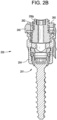
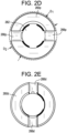
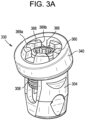
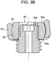
- FIGS. 2A-2E illustrate an exemplary connector assembly 200 that includes a locking spherical articulation joint. Except as described below or as will be readily appreciated by one having ordinary skill in the art, the structure and operation of the connector assembly 200 is substantially the same as that of the connector assembly 100 described above.
- the slits 266p formed in the proximal surface 260p can be angularly offset relative to the slits 266d formed in the distal surface 260d about the circumference of the locking nut 260. For example, a 90 degree offset can be used as shown.
- the slits 266p formed in the proximal surface 260p can be used as a drive feature to receive a driver instrument for rotating the locking nut 260 about the set screw 208 to further thread the locking nut 260 onto the set screw 208.
- the threads of the set screw 208 can be conical or tapered and the threads of the locking nut 260 can be cylindrical.
- the conical threads can taper at an angle of about 2 degrees to about 10 degrees from a rotation axis of the locking nut 260.
- the conical threads can taper at an angle of about 5 degrees to about 10 degrees from a rotation axis of the locking nut 260.
- the threads can have a tapered major diameter, a tapered minor diameter, or both.
- the set screw 208 can be disposed in the receiver member 204 of a bone anchor assembly 201 to secure a first rod (not shown) within the bone anchor assembly.
- the connector 230 can be located on the proximal end 208p of the set screw 208, for example, after the first rod is fixed within the receiver member 204.
- the locking nut 260 can be received within the opening 242 of the connector and at least partially threaded onto the set screw 208 to retain the connector 230 on the set screw.
- the distal surface 662d can include rotation resisting features such as spaced apart tabs 664a, 664b that project distally therefrom.
- the tabs 664a, 664b can be spaced apart to define a recess 665 therebetween for receiving the respective arms 604a, 604b of the receiver member 604.
- the tabs 664a, 664b can have a width that is substantially the same as the width of the recess 620 defined by the arms 604a, 604b of the receiver member.
- the tabs 664a, 664b can include a lip 668 that radially projects therefrom to aid in retaining the positioner 660 within the connector 630, as described further below.
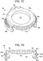
- the positioner 760 can generally include a ring shaped body 762.
- the ring shaped body 762 can include a central opening 763, proximal and distal surfaces 762p, 762d, and an outer sidewall 762s.
- the body 762 can include a first hemisphere or first portion 767a and a second hemisphere or second portion 767b.
- the positioner 760 can include rotation-resisting features configured to interact with the receiver member 704 to limit or prevent rotation between the positioner 760 and the receiver member 704 about the axis A1.
- the positioner 760 can include spaced apart tabs 764a, 764b that project distally therefrom.
- the tabs 764a, 764b can be spaced apart to define recesses 765 therebetween for receiving the respective arms 704a, 704b of the receiver member 704.
- the tabs 764a, 764b can have a width that is substantially the same as the width of the channel 720 defined by the arms 704a, 704b of the receiver member 704. When inserted between the arms 704a, 704b of the receiver member 704, the tabs 764a, 764b can prevent rotation of the positioner 760 relative to the receiver member 704 about the axis A1.
- Each tab 764a, 764b can include a first lip 768a that projects radially outward therefrom to aid in retaining the positioner 760 within the connector 730, as described further below.
- the first lip 768a can have a ramped, curved, or otherwise tapered proximal-facing lead-in surface to facilitate assembly with the connector 730.
- the tapered surface can allow the first lip 768a to ride over a ledge 725 of the connector 730 and snap-fit into a groove 748 formed in the connector 730.
- Cut-outs or other reliefs 769 can be formed at the junction between the tabs 764 and the body 762 to facilitate deflection or bending of the tabs towards and/or away from one another, e.g., during snap-fitting into the connector 730 or during clamping onto the set screw 708.
- the positioner 760 can include features for selectively locking rotation between the positioner and the connector 730 about the axis A1.
- the body 762 can include one or more teeth 766 projecting radially outward therefrom.
- the teeth 766 can engage or be enmeshed with corresponding teeth 729 formed in the connector 730 to lock rotation between the positioner 760 and the connector. While three teeth 766 are shown, it will be appreciated that the body 762 can include any number of teeth, or the teeth can be omitted altogether.
- the teeth 766 can be formed only in the first portion 767a of the body 762 as shown, or can be formed at any location about the circumference of the body.
- the surfaces of the teeth 766 that contact and bear against the teeth of the connector 730 can be rounded, chamfered, or otherwise shaped to facilitate release of the positioner 760 from the connector 730. This can advantageously help mobilize the construct when the assembly is loosened, e.g., to reposition the construct before final tightening.
- the body 762 can include one or more flats 723 formed in the outer sidewall 762s of the body.
- the outer sidewall 762s can be cylindrical.
- the flats 723 can engage or bear against one or more corresponding flats 727 formed in an inner sidewall 745 of the connector 730 to lock rotation between the positioner 760 and the connector.
- the flats 723 can be formed only in the second portion 767b of the body 762 as shown, or can be formed at any location about the circumference of the body. While flats are shown, it will be appreciated that the positioner 760 can include other eccentric features to perform a similar function, such as lobes, teeth, etc.
- both the first and second portions 767a, 767b of the body 762 can include teeth 766. In some embodiments, both the first and second portions 767a, 767b of the body 762 can include flats 723. In some embodiments, the first portion 767a of the body 762 can include teeth 766 and the second portion 767b of the body can include flats 723. In this arrangement, the positioner 760 can be oriented in the connector 730 such that the second portion 767b is adjacent to, or closer to, the rod slot of the connector. In some instances, to achieve the desired center-to-center offset of the first and second rods, the material thickness of the connector 730 adjacent to the rod slot of the connector may be limited such that use of teeth 766 in this area is impractical.
- flats 723 can be used in place of teeth on the second portion 767b of the positioner 760 such that the positioner 760 still includes rotation-preventing features on both the first portion 767a and the second portion 767b, even when the material thickness of the connector is limited.
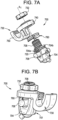
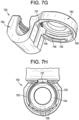
- the connector 730 is shown in more detail in FIGS. 7G-7H .
- the connector 730 can include a first portion 740 for mating the connector with a bone anchor assembly 701 and a second portion 750 for mating the connector with a fixation element such as an elongate spinal rod.
- the illustrated second portion 750 is exemplary, and the connector 730 can include any of the second portions described herein.
- the first portion 740 of the connector 730 can include a recess 744 configured to receive the positioner 760.
- the recess 744 can be defined at least in part by a sidewall 745.
- a groove 748 can be formed in the sidewall 745 and can define a distal ledge 725.
- the groove 748 can be sized and shaped to receive the first lips 768a of the positioner 760 to retain the positioner within the recess 744.
- the ledge 725 can define a ramped, curved, or otherwise tapered distal-facing lead-in surface. In some embodiments, the ramped surface of the ledge 725 can extend at an angle in the range of about 30 degrees to about 60 degrees from the horizontal. In some embodiments, the ramped surface of the ledge 725 can extend at an angle of about 45 degrees from the horizontal.
- the tapered proximal-facing surface of the first lips 768a can ride over the tapered distal-facing surface of the ledge 725 to deflect the arms 764 of the positioner inward until the positioner is advanced more proximally and the first lips 768a snap-fit into the groove 748.
- the first lips 768a can be configured to slide within the groove 748 such that the positioner 760 can rotate within the connector 730 prior to tightening the assembly 700.
- the degree to which the positioner 760 can rotate within the connector 730 prior to tightening can be limited.
- the groove 748 can extend along less than the entire inner circumference of the sidewall 745.
- the illustrated groove 748 terminates at or near the 11 o'clock and 1 o'clock positions in FIG. 7H .
- the terminations of the groove 748 can define stop surfaces configured to contact the first lips 768a to limit rotation of the positioner 760 within the connector 730.
- the groove 748 can have a height along the axis A1 that is greater than a corresponding height of the lips 768a such that a limited amount of axial travel of the positioner 760 relative to the connector 730 along the axis A1 is permitted before the assembly 700 is tightened.
- the teeth 729 can engage or be enmeshed with corresponding teeth 766 of the positioner 760 to lock rotation between the positioner 760 and the connector 730. While four teeth 729 are shown, it will be appreciated that the connector 730 can include any number of teeth, or the teeth can be omitted altogether.
- the surfaces of the teeth 729 that contact and bear against the teeth 766 of the positioner 760 can be rounded, chamfered, or otherwise shaped to facilitate release of the positioner 760 from the connector 730. This can advantageously help mobilize the construct when the assembly is loosened, e.g., to reposition the construct before final tightening. Such surface features can also facilitate alignment of the teeth 766, 729 as the construct is tightened.
- the connector 730 and the positioner 760 can rotate relative to each other about the axis A1.
- the teeth 766, 729 can become enmeshed to resist or prevent such rotation.
- the flats 723, 727 can likewise engage with one another when the nut 732 is tightened to provide further resistance to rotation between the connector 730 and the positioner 760.
- interaction between the teeth 729, 766 and interaction between the flats 723, 727 can allow the positioner 760 to be placed and locked in any of a plurality of discrete rotational positions relative to the connector 730.
- the connector 730 can be placed and locked in any of a plurality of discrete rotational positions relative to the receiver member 704.
- the assembly can include teeth only, flats only, or neither teeth nor flats. In the latter arrangement, locking can be achieved by frictional engagement between the proximal surface of the positioner and the distal surface of the connector when the nut 732 is tightened. In this arrangement, the positioner can be positioned in any of an infinite number of rotational positions relative to the connector.
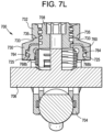
- the assembly 700 can include features to help ensure consistent and efficient tightening torque when tightening the nut 732.
- the proximal surface of the connector 730 can include a raised protrusion 733.
- the protrusion 733 can define a proximal-facing contact surface, which can be ramped, curved, or otherwise tapered.
- the protrusion 733 defines a male conical surface.
- the nut 732 can include a complementary distal-facing contact surface 735 which can be ramped, curved, or otherwise tapered.
- the contact surface 735 of the nut 732 defines a female conical surface.
- the connector assembly can include various features for positioning the second rod at a desired proximal-distal height relative to the first rod.
- the second rod-receiving recess 852 can be elongated in the proximal-distal direction to allow the second rod 807 to be positioned distal to the first rod 806.
- the connector 830 can be used to position the second rod 807 anterior to the first rod 806 when the assembly is attached to the posterior aspects of a patient's spine.
- the second rod-receiving recess 852 can extend to a distal most rod seat 852d that is more distal than the rod seat 820d of the first rod-receiving recess 820.
- the connector 930 can be configured to position the second rod 907 proximal to the first rod 906.
- the connector 930 can be used to position the second rod 907 posterior to the first rod 906 when the assembly is attached to the posterior aspects of a patient's spine.
- the first and second arms 952a, 952b of the connector 930 can extend proximally above the proximal surface 940p of the first portion 940 of the connector to define a second rod receiving recess 952 having a rod seat 952d that is proximal to the rod seat 920d of the receiver member 904. While the second rod-receiving recess 952 is shown as being straight, it will be appreciated that the recess can be curved or angled as described above.
- Each of the arms 952a, 952b can include a feature such as a recess, dimple, notch, projection, or the like, to facilitate coupling of the connector 930 to various instruments.
- the outer surface of each arm 952a, 952b can include an arcuate groove 954a, 954b at the respective proximal end of the arms for attaching the connector 930 to an extension tower or retractor.
- the arms 952a, 952b can include or can be coupled to extension or reduction tabs (not shown) that extend proximally from the connector 930 to functionally extend the length of the arms 952a, 952b.
- the extension tabs can facilitate insertion and reduction of a rod or other implant, as well as insertion and locking of the second set screw 934.
- the extension tabs can be configured to break away or otherwise be separated from the arms 952a, 952b.
- the second rod seat 1052d can be defined by one or more ramped or tapered surfaces.
- the second rod seat 1052d is V-shaped with opposed planar surfaces 1073 that converge towards one another in a distal direction.
- a connector having this geometry can advantageously allow second rods of various different diameters to be locked securely within the recess 1052.
- any of the connectors herein can include a spherical articulation joint, a gimbal interface, an elongated connector opening, a uniplanar recess, or a complete locking recess. Any of the connectors herein can be configured for use with any of the positioners herein to selectively limit rotation of the connector relative to a receiver member.
- a second spinal rod 107 can be inserted into the second rod-receiving recess 152 of the connector 130.
- the second rod 107 can be provisionally secured within the recess 152 by partially tightening the second set screw 134.
- the connector 130, the receiver member 104, and/or the rods 106, 107 can be manipulated by the user to position the construct as desired, e.g., to obtain the desired correction.
- the connector can be pivoted about a spherical articulation joint or gimbal interface of the type described herein.
- the first and second set screws 108, 134 and the nut 132 can be tightened in any sequence to lock the construct.
- the first set screw 108 can be tightened to lock polyaxial movement of the receiver member 104 relative to the bone anchor portion 102 and to lock the first rod 106 within the receiver member 104.
- the second set screw 134 can be tightened to lock the second rod 107 within the connector 130.
- the nut 132 can be tightened to lock the relative position between the connector 130 and the receiver member 104.
- the first rod 106 and/or the second rod 107 can be secured to the patient's spine using additional bone anchor assemblies, for example implanted in adjacent or nearby vertebrae, such as an adjacent vertebra V2.
- additional bone anchor assemblies for example implanted in adjacent or nearby vertebrae, such as an adjacent vertebra V2.
- Multiple connector assemblies can be used to attach additional rods to the construct, or to secure the first and second rods at another position on their respective lengths to another vertebra.
Landscapes
- Health & Medical Sciences (AREA)
- Orthopedic Medicine & Surgery (AREA)
- Life Sciences & Earth Sciences (AREA)
- Surgery (AREA)
- Neurology (AREA)
- Heart & Thoracic Surgery (AREA)
- Engineering & Computer Science (AREA)
- Biomedical Technology (AREA)
- Nuclear Medicine, Radiotherapy & Molecular Imaging (AREA)
- Medical Informatics (AREA)
- Molecular Biology (AREA)
- Animal Behavior & Ethology (AREA)
- General Health & Medical Sciences (AREA)
- Public Health (AREA)
- Veterinary Medicine (AREA)
- Surgical Instruments (AREA)
- Prostheses (AREA)
Applications Claiming Priority (3)
| Application Number | Priority Date | Filing Date | Title |
|---|---|---|---|
| US15/430,188 US10238432B2 (en) | 2017-02-10 | 2017-02-10 | Tandem rod connectors and related methods |
| PCT/US2018/017034 WO2018148193A2 (en) | 2017-02-10 | 2018-02-06 | Tandem rod connectors and related methods |
| EP18706089.2A EP3579770B1 (de) | 2017-02-10 | 2018-02-06 | Tandemstangenverbinder |
Related Parent Applications (1)
| Application Number | Title | Priority Date | Filing Date |
|---|---|---|---|
| EP18706089.2A Division EP3579770B1 (de) | 2017-02-10 | 2018-02-06 | Tandemstangenverbinder |
Publications (3)
| Publication Number | Publication Date |
|---|---|
| EP4397259A2 true EP4397259A2 (de) | 2024-07-10 |
| EP4397259A3 EP4397259A3 (de) | 2024-09-11 |
| EP4397259B1 EP4397259B1 (de) | 2025-08-13 |
Family
ID=61244763
Family Applications (2)
| Application Number | Title | Priority Date | Filing Date |
|---|---|---|---|
| EP18706089.2A Active EP3579770B1 (de) | 2017-02-10 | 2018-02-06 | Tandemstangenverbinder |
| EP24176474.5A Active EP4397259B1 (de) | 2017-02-10 | 2018-02-06 | Tandemstangenverbinder |
Family Applications Before (1)
| Application Number | Title | Priority Date | Filing Date |
|---|---|---|---|
| EP18706089.2A Active EP3579770B1 (de) | 2017-02-10 | 2018-02-06 | Tandemstangenverbinder |
Country Status (6)
| Country | Link |
|---|---|
| US (4) | US10238432B2 (de) |
| EP (2) | EP3579770B1 (de) |
| JP (1) | JP7106554B2 (de) |
| CN (1) | CN110312484B (de) |
| AU (1) | AU2018218225B2 (de) |
| WO (1) | WO2018148193A2 (de) |
Families Citing this family (56)
| Publication number | Priority date | Publication date | Assignee | Title |
|---|---|---|---|---|
| US9247964B1 (en) * | 2011-03-01 | 2016-02-02 | Nuasive, Inc. | Spinal Cross-connector |
| FR3034978B1 (fr) * | 2015-04-17 | 2017-04-07 | Implanet | Systeme, piece et procede d'ancrage vertebral. |
| US9855078B2 (en) * | 2015-10-05 | 2018-01-02 | Globus Medical, Inc. | Spinal anchoring system |
| US10206718B1 (en) * | 2016-02-17 | 2019-02-19 | Seaspine Orthopedics Corporation | Implantable connector |
| US9962192B2 (en) | 2016-03-17 | 2018-05-08 | Medos International Sarl | Multipoint fixation implants |
| US10321939B2 (en) | 2016-05-18 | 2019-06-18 | Medos International Sarl | Implant connectors and related methods |
| US10517647B2 (en) | 2016-05-18 | 2019-12-31 | Medos International Sarl | Implant connectors and related methods |
| US10786285B2 (en) | 2016-06-06 | 2020-09-29 | Stryker European Holdings I, Llc | Paraxial revision rod-to-rod connector |
| EP3278751B1 (de) | 2016-07-15 | 2024-03-06 | Stryker European Operations Holdings LLC | Wirbelsäulenfixierungsanordnung |
| US10966760B2 (en) | 2016-10-28 | 2021-04-06 | Warsaw Orthopedic, Inc. | Spinal implant system and method |
| KR101910597B1 (ko) * | 2016-12-02 | 2018-10-22 | 안경기 | 고정막대 연결장치 |
| US10398476B2 (en) | 2016-12-13 | 2019-09-03 | Medos International Sàrl | Implant adapters and related methods |
| US10492835B2 (en) | 2016-12-19 | 2019-12-03 | Medos International Sàrl | Offset rods, offset rod connectors, and related methods |
| US10238432B2 (en) | 2017-02-10 | 2019-03-26 | Medos International Sàrl | Tandem rod connectors and related methods |
| US20180228516A1 (en) * | 2017-02-14 | 2018-08-16 | Warsaw Orthopedic, Inc. | Spinal implant system and method |
| US10736665B2 (en) * | 2017-02-24 | 2020-08-11 | Warsaw Orthopedic, Inc. | Spinal implant system and method |
| US10561454B2 (en) | 2017-03-28 | 2020-02-18 | Medos International Sarl | Articulating implant connectors and related methods |
| US10966761B2 (en) | 2017-03-28 | 2021-04-06 | Medos International Sarl | Articulating implant connectors and related methods |
| EP3610812B1 (de) * | 2017-04-12 | 2023-10-11 | Gangneung-Wonju National University Industry Academy Cooperation Group | Verbinder zur gleichzeitigen befestigung von schraubenkopf und stab |
| US11648037B2 (en) | 2017-05-03 | 2023-05-16 | Advance Research System, Llc | Extension-ready spinal support system with vascular-safe pedicle screw |
| US10966758B2 (en) | 2017-05-03 | 2021-04-06 | Advance Research System, Llc | Reinforcement caps for spinal support systems |
| US10456174B2 (en) | 2017-07-31 | 2019-10-29 | Medos International Sarl | Connectors for use in systems and methods for reducing the risk of proximal junctional kyphosis |
| US10463403B2 (en) | 2017-07-31 | 2019-11-05 | Medos International Sarl | Systems and methods for reducing the risk of proximal junctional kyphosis using a bone anchor or other attachment point |
| US11076890B2 (en) | 2017-12-01 | 2021-08-03 | Medos International Sàrl | Rod-to-rod connectors having robust rod closure mechanisms and related methods |
| US10966762B2 (en) | 2017-12-15 | 2021-04-06 | Medos International Sarl | Unilateral implant holders and related methods |
| US10898232B2 (en) | 2018-03-20 | 2021-01-26 | Medos International Sàrl | Multipoint fixation implants and related methods |
| WO2020154435A1 (en) * | 2019-01-22 | 2020-07-30 | Life Spine, Inc | Polyaxial spine screw rod holder having a second, offset rod holder |
| EP3695796B1 (de) * | 2019-02-13 | 2022-08-03 | Biedermann Technologies GmbH & Co. KG | Verankerungsanordnung zur verankerung eines stabes an einem knochen oder einem wirbel |
| US11291482B2 (en) | 2019-03-21 | 2022-04-05 | Medos International Sarl | Rod reducers and related methods |
| USD1004774S1 (en) | 2019-03-21 | 2023-11-14 | Medos International Sarl | Kerrison rod reducer |
| US11291481B2 (en) | 2019-03-21 | 2022-04-05 | Medos International Sarl | Rod reducers and related methods |
| WO2020237061A2 (en) | 2019-05-22 | 2020-11-26 | Nuvasive, Inc. | Posterior spinal fixation screws |
| EP3995093B1 (de) * | 2019-07-01 | 2025-08-06 | Mizuho Corporation | Korrekturvorrichtung |
| US11864801B2 (en) | 2019-07-31 | 2024-01-09 | Seaspine, Inc. | Implantable universal connector |
| US11311317B2 (en) * | 2019-09-25 | 2022-04-26 | Stelios KOUTSOUMBELIS | Spinal fixation device with rotatable connector |
| US11426210B2 (en) | 2019-09-25 | 2022-08-30 | Medos International Sàrl | Multipoint angled fixation implants for multiple screws and related methods |
| US11653953B2 (en) * | 2019-10-11 | 2023-05-23 | Medos International Sarl | Implant receivers and connectors with grip grooves for rod fixation |
| JP7676711B2 (ja) | 2020-02-14 | 2025-05-15 | メドス・インターナショナル・エスエイアールエル | 統合された多点固定ねじ |
| CN111329568B (zh) * | 2020-04-03 | 2023-04-11 | 贵州医科大学附属医院 | 一种脊柱的柔性组合式固定装置 |
| USD951451S1 (en) * | 2020-09-03 | 2022-05-10 | Solco Biomedical Co., Ltd. | Cross link for cervical vertebrae |
| USD951450S1 (en) * | 2020-09-03 | 2022-05-10 | Solco Biomedical Co., Ltd. | Side screw for cervical vertebrae |
| USD951452S1 (en) * | 2020-09-03 | 2022-05-10 | Solco Biomedical Co., Ltd. | Rod connector for cervical vertebrae |
| US12213706B2 (en) | 2020-10-07 | 2025-02-04 | Globus Medical, Inc. | Systems and methods for surgical procedures using band clamp implants and tensioning instruments |
| US12458420B2 (en) | 2020-10-07 | 2025-11-04 | Globus Medical, Inc. | Systems and methods for surgical procedures using band clamp implants and tensioning instruments |
| US11771475B2 (en) | 2020-10-07 | 2023-10-03 | Globus Medical, Inc. | Systems and methods for surgical procedures using band clamp implants and tensioning instruments |
| US11974785B2 (en) | 2020-10-16 | 2024-05-07 | Globus Medical, Inc | Band clamp implants |
| US12318121B2 (en) | 2020-11-09 | 2025-06-03 | Medos International Sàrl | Biplanar forceps reducers and methods of use |
| US11284924B1 (en) | 2020-12-16 | 2022-03-29 | Warsaw Orthopedic, Inc | Adjustable spinal implant, system and method |
| US11350969B1 (en) | 2021-02-02 | 2022-06-07 | Warsaw Orthopedic, Inc. | Rotatable spinal implant, system, and method |
| US11998244B2 (en) | 2021-04-09 | 2024-06-04 | Snj Patents, Llc | Minimally invasive surgery add on screw system |
| JP2024538403A (ja) | 2021-11-19 | 2024-10-18 | メドス・インターナショナル・エスエイアールエル | 整復係止機構 |
| JP2025503170A (ja) * | 2022-01-26 | 2025-01-30 | ニューヴェイジヴ,インコーポレイテッド | ロッド間コネクタインプラント |
| US11849979B1 (en) * | 2022-05-16 | 2023-12-26 | Warsaw Orthopedic, Inc. | Spinal implant system and method |
| CA3265013A1 (en) * | 2022-08-16 | 2024-02-22 | Chris Danek | TULIP-FORMING SIDE-MOUNTED CABINETS, SYSTEMS AND METHODS |
| US11890033B1 (en) | 2022-10-28 | 2024-02-06 | Warsaw Orthopedic, Inc. | Spinal implant system and method |
| US12433644B2 (en) * | 2022-11-17 | 2025-10-07 | Warsaw Orthopedic, Inc. | Multiaxial receivers with tether |
Citations (6)
| Publication number | Priority date | Publication date | Assignee | Title |
|---|---|---|---|---|
| US6736820B2 (en) | 2000-11-10 | 2004-05-18 | Biedermann Motech Gmbh | Bone screw |
| US6974460B2 (en) | 2001-09-14 | 2005-12-13 | Stryker Spine | Biased angulation bone fixation assembly |
| US7179261B2 (en) | 2003-12-16 | 2007-02-20 | Depuy Spine, Inc. | Percutaneous access devices and bone anchor assemblies |
| US9155580B2 (en) | 2011-08-25 | 2015-10-13 | Medos International Sarl | Multi-threaded cannulated bone anchors |
| US9265548B2 (en) | 2008-10-30 | 2016-02-23 | DePuy Synthes Products, Inc. | Systems and methods for delivering bone cement to a bone anchor |
| US9433445B2 (en) | 2013-03-14 | 2016-09-06 | DePuy Synthes Products, Inc. | Bone anchors and surgical instruments with integrated guide tips |
Family Cites Families (351)
| Publication number | Priority date | Publication date | Assignee | Title |
|---|---|---|---|---|
| US5261909A (en) * | 1992-02-18 | 1993-11-16 | Danek Medical, Inc. | Variable angle screw for spinal implant system |
| US5312405A (en) | 1992-07-06 | 1994-05-17 | Zimmer, Inc. | Spinal rod coupler |
| ZA937672B (en) | 1992-10-22 | 1994-05-16 | Danek Medical Inc | Spinal rod transverse connector for supporting vertebral fixation elements |
| US5584831A (en) | 1993-07-09 | 1996-12-17 | September 28, Inc. | Spinal fixation device and method |
| JP2605313Y2 (ja) | 1993-12-28 | 2000-07-10 | 旭光学工業株式会社 | 脊椎後方矯正部材の固定具 |
| DE4425357C2 (de) | 1994-07-18 | 1996-07-04 | Harms Juergen | Verankerungselement |
| US5716355A (en) | 1995-04-10 | 1998-02-10 | Sofamor Danek Group, Inc. | Transverse connection for spinal rods |
| US5613968A (en) * | 1995-05-01 | 1997-03-25 | Lin; Chih-I | Universal pad fixation device for orthopedic surgery |
| AU5935196A (en) | 1995-06-06 | 1996-12-24 | Sdgi Holdings, Inc. | Device for linking adjacent rods in spinal instrumentation |
| US5669910A (en) | 1996-01-02 | 1997-09-23 | Pioneer Laboratories, Inc. | Crosslink for implantable rods |
| US5709685A (en) * | 1996-05-21 | 1998-01-20 | Sdgi Holdings, Inc. | Positionable clip for provisionally capturing a component on a spinal rod |
| US5769857A (en) | 1996-06-11 | 1998-06-23 | Mgf Group Inc. | Ligating clip applier |
| US5885284A (en) | 1996-07-11 | 1999-03-23 | Third Millennium Engineering, L.L.C. | Hinged variable length cross-link device |
| JP2871620B2 (ja) * | 1996-09-06 | 1999-03-17 | 株式会社ロバート・リード商会 | 骨固定装置 |
| US5725528A (en) * | 1997-02-12 | 1998-03-10 | Third Millennium Engineering, Llc | Modular polyaxial locking pedicle screw |
| US6171311B1 (en) | 1996-10-18 | 2001-01-09 | Marc Richelsoph | Transverse connector |
| US5776135A (en) | 1996-12-23 | 1998-07-07 | Third Millennium Engineering, Llc | Side mounted polyaxial pedicle screw |
| FR2761256B1 (fr) | 1997-04-01 | 1999-06-11 | Daniel Chopin | Instrumentation d'osteosynthese rachidienne a connecteur de liaison entre une tige vertebrale et des organes d'ancrage osseux |
| FR2761590B1 (fr) | 1997-04-04 | 1999-08-20 | Stryker France Sa | Dispositif d'osteosynthese du rachis a fixation de tige intervertebrale desaxee |
| US6783526B1 (en) | 1997-05-15 | 2004-08-31 | Howmedica Osteonics Corp. | Transverse rod connector clip |
| DE69721278T2 (de) * | 1997-12-17 | 2004-02-05 | Robert Lange | Apparat zur Stabilisierung bestimmter Wirbel der Wirbelsäule |
| US5980523A (en) | 1998-01-08 | 1999-11-09 | Jackson; Roger | Transverse connectors for spinal rods |
| US6083226A (en) | 1998-04-22 | 2000-07-04 | Fiz; Daniel | Bone fixation device and transverse linking bridge |
| DE29808593U1 (de) | 1998-05-13 | 1999-09-23 | Howmedica GmbH, 24232 Schönkirchen | Vorrichtung zum Verbinden von zwei beabstandeten Längsstäben eines Wirbelsäulenimplantats |
| US6264658B1 (en) | 1998-07-06 | 2001-07-24 | Solco Surgical Instruments Co., Ltd. | Spine fixing apparatus |
| FR2781663B1 (fr) * | 1998-07-30 | 2000-10-13 | Materiel Orthopedique En Abreg | Dispositif d'osteosynthese rachidienne |
| US6231575B1 (en) | 1998-08-27 | 2001-05-15 | Martin H. Krag | Spinal column retainer |
| US6050997A (en) | 1999-01-25 | 2000-04-18 | Mullane; Thomas S. | Spinal fixation system |
| KR100324698B1 (ko) | 1999-01-30 | 2002-02-27 | 구자교 | 척추고정장치 |
| DE60032225T2 (de) | 1999-03-30 | 2007-09-13 | Howmedica Osteonics Corp. | Apparat zur stabilisierung der wirbelsäule |
| US6328739B1 (en) * | 1999-05-04 | 2001-12-11 | Industrial Technology Research Institute | Enhanced spine fixation apparatus |
| US7122036B2 (en) | 1999-07-01 | 2006-10-17 | Spinevision, S.A. | Connector for an osteosynthesis system intended to provide a connection between two rods of a spinal osteosynthesis system, osteosynthesis system using such a connector, and method of implanting such an osteosynthesis system |
| FR2796546B1 (fr) | 1999-07-23 | 2001-11-30 | Eurosurgical | Connecteur polyaxial pour implant rachidien |
| US6238396B1 (en) | 1999-10-07 | 2001-05-29 | Blackstone Medical, Inc. | Surgical cross-connecting apparatus and related methods |
| FR2801778B1 (fr) | 1999-12-03 | 2002-02-08 | Spinevision | Ensemble de connexion pour le domaine de l'osteosynthese rachidienne |
| FR2804314B1 (fr) * | 2000-01-27 | 2003-01-31 | Scientx | Dispositif de liaison intervertebrale avec une barre de connexion pour la fixation d'une tige de liaison |
| US6562038B1 (en) | 2000-03-15 | 2003-05-13 | Sdgi Holdings, Inc. | Spinal implant connection assembly |
| US6616668B2 (en) | 2000-06-09 | 2003-09-09 | Cross Medical Products, Inc. | Adjustable transverse connector for use with a spinal implant system |
| US6551318B1 (en) * | 2000-07-26 | 2003-04-22 | Stahurski Consulting Inc. | Spinal column retaining apparatus |
| US6524310B1 (en) | 2000-08-18 | 2003-02-25 | Blackstone Medical, Inc. | Surgical cross-connecting apparatus having locking lever |
| US6554831B1 (en) * | 2000-09-01 | 2003-04-29 | Hopital Sainte-Justine | Mobile dynamic system for treating spinal disorder |
| US6485491B1 (en) * | 2000-09-15 | 2002-11-26 | Sdgi Holdings, Inc. | Posterior fixation system |
| US6620164B2 (en) | 2000-09-22 | 2003-09-16 | Showa Ika Kohgyo Co., Ltd. | Rod for cervical vertebra and connecting system thereof |
| US7485132B1 (en) | 2000-10-06 | 2009-02-03 | Abbott Spine Inc. | Transverse connector with cam activated engagers |
| FR2816195B1 (fr) | 2000-11-07 | 2003-01-03 | Medicrea | Materiel d'arthrodese vertebrale |
| FR2817929B1 (fr) | 2000-12-07 | 2003-03-21 | Spine Next Sa | Dispositif de fixation d'une tige et d'une tete de vis a symetrie spherique |
| US6602253B2 (en) | 2001-02-12 | 2003-08-05 | Marc Richelsoph | Rod to rod connector |
| US6554832B2 (en) | 2001-04-02 | 2003-04-29 | Endius Incorporated | Polyaxial transverse connector |
| EP1591072B1 (de) | 2001-04-24 | 2008-01-02 | coLigne AG | Instrumentarium zur Stabilisierung gewisser Wirbel der Wirbelsäule |
| US6478798B1 (en) | 2001-05-17 | 2002-11-12 | Robert S. Howland | Spinal fixation apparatus and methods for use |
| EP1357829B1 (de) | 2001-05-23 | 2010-10-13 | Boss Instruments, Ltd. | Retraktorklemmenzusammenstellung |
| FR2826861B1 (fr) * | 2001-07-04 | 2004-06-18 | Materiel Orthopedique En Abreg | Connecteur lateral a decalage ajustable pour dispositif de correction et de stabilisation du rachis, organe de fixation adapte a ce connecteur et ensemble forme par ce connecteur et cet organe de fixation |
| US6793657B2 (en) | 2001-09-10 | 2004-09-21 | Solco Biomedical Co., Ltd. | Spine fixing apparatus |
| US20060079892A1 (en) * | 2001-10-31 | 2006-04-13 | Suranjan Roychowdhury | Adjustable tandem connectors for corrective devices for the spinal column and other bones and joints |
| FR2832620B1 (fr) | 2001-11-27 | 2004-01-23 | Eurosurgical | Connecteur pour systeme d'ancrage vertebral |
| FR2835174B1 (fr) | 2002-01-31 | 2004-03-19 | Materiel Orthopedique En Abreg | Connecteur pour dispositif d'osteosynthese rachidienne, ensemble connecteur/organe d'ancrage osseux et dispositif d'osteosynthese rachidienne utilisant cet ensemble |
| JP2003232314A (ja) | 2002-02-08 | 2003-08-22 | Showa Ika Kohgyo Co Ltd | ロッド間隔保持具 |
| FR2835734B1 (fr) | 2002-02-11 | 2004-10-29 | Scient X | Systeme de liaison entre une tige rachidienne et une barre transversale |
| US7163538B2 (en) | 2002-02-13 | 2007-01-16 | Cross Medical Products, Inc. | Posterior rod system |
| FR2836368B1 (fr) | 2002-02-25 | 2005-01-14 | Spine Next Sa | Dispositif de liaison sequentiel |
| US8029543B2 (en) | 2002-10-28 | 2011-10-04 | Warsaw Othopedic, Inc. | Multi-axial, cross-link connector system for spinal implants |
| US20040111088A1 (en) * | 2002-12-06 | 2004-06-10 | Picetti George D. | Multi-rod bone attachment member |
| DE10260222B4 (de) | 2002-12-20 | 2008-01-03 | Biedermann Motech Gmbh | Rohrförmiges Element für ein in der Wirbelsäulen- oder der Knochenchirurgie zu verwendendes Implantat und Implantat mit einem solchen Element |
| US20040162558A1 (en) * | 2003-02-18 | 2004-08-19 | Hegde Sajan K. | Spinal plate having an integral rod connector portion |
| US7918876B2 (en) | 2003-03-24 | 2011-04-05 | Theken Spine, Llc | Spinal implant adjustment device |
| FR2856581B1 (fr) * | 2003-06-27 | 2005-08-19 | Medicrea | Materiel d'osteosynthese vertebrale |
| FR2856579B1 (fr) * | 2003-06-27 | 2006-03-17 | Medicrea | Materiel d'osteosynthese vertebrale et procede de fabrication d'un organe d'ancrage osseux que comprend ce materiel |
| FR2856580B1 (fr) * | 2003-06-27 | 2006-03-17 | Medicrea | Materiel d'osteosynthese vertebrale |
| US8308772B2 (en) * | 2003-06-27 | 2012-11-13 | Medicrea Technologies | Vertebral osteosynthesis equipment |
| US7731734B2 (en) * | 2003-06-27 | 2010-06-08 | Medicrea Technologies | Vertebral osteosynthesis equipment |
| US7771474B2 (en) | 2003-07-01 | 2010-08-10 | Seaspine, Inc. | Transverse connector system |
| FR2859095B1 (fr) * | 2003-09-01 | 2006-05-12 | Ldr Medical | Implant d'ancrage osseux a tete polyaxiale et procede de mise en place de l'implant |
| US7736370B2 (en) | 2003-10-21 | 2010-06-15 | Zimmer Spine, Inc. | Method for interconnecting longitudinal members extending along a spinal column |
| US7744633B2 (en) | 2003-10-22 | 2010-06-29 | Pioneer Surgical Technology, Inc. | Crosslink for securing spinal rods |
| FR2861981B1 (fr) | 2003-11-10 | 2006-08-04 | Medicrea | Materiel d'osteosynthese vertebrale |
| GB0326888D0 (en) | 2003-11-19 | 2003-12-24 | Depuy Int Ltd | A hook |
| US7569069B2 (en) | 2003-12-19 | 2009-08-04 | Orthopaedic International, Inc. | Transverse connector for rod-based spinal implants |
| US7104993B2 (en) | 2004-02-10 | 2006-09-12 | Atlas Spine, Inc. | Cross link system |
| US8998952B2 (en) * | 2004-02-17 | 2015-04-07 | Globus Medical, Inc. | Facet joint replacement instruments and methods |
| GB0406822D0 (en) * | 2004-03-25 | 2004-04-28 | Depuy Int Ltd | Surgical fastening |
| US8236028B2 (en) * | 2004-03-31 | 2012-08-07 | Depuy Spine Sarl | Spinal rod connector |
| US7909852B2 (en) | 2004-03-31 | 2011-03-22 | Depuy Spine Sarl | Adjustable-angle spinal fixation element |
| US7717939B2 (en) | 2004-03-31 | 2010-05-18 | Depuy Spine, Inc. | Rod attachment for head to head cross connector |
| US7645294B2 (en) * | 2004-03-31 | 2010-01-12 | Depuy Spine, Inc. | Head-to-head connector spinal fixation system |
| US20050228377A1 (en) | 2004-04-07 | 2005-10-13 | Depuy Spine, Inc. | Spinal cross-connectors |
| US20050228382A1 (en) | 2004-04-12 | 2005-10-13 | Marc Richelsoph | Screw and rod fixation assembly and device |
| US7744635B2 (en) * | 2004-06-09 | 2010-06-29 | Spinal Generations, Llc | Spinal fixation system |
| US7744634B2 (en) | 2004-06-15 | 2010-06-29 | Warsaw Orthopedic, Inc. | Spinal rod system |
| US8034082B2 (en) | 2004-07-08 | 2011-10-11 | Globus Medical, Inc. | Transverse fixation device for spinal fixation systems |
| EP1627608B1 (de) | 2004-08-20 | 2009-05-06 | Stryker Trauma SA | Klemmelement und Gelenkelement |
| US8951290B2 (en) * | 2004-08-27 | 2015-02-10 | Blackstone Medical, Inc. | Multi-axial connection system |
| US7717938B2 (en) | 2004-08-27 | 2010-05-18 | Depuy Spine, Inc. | Dual rod cross connectors and inserter tools |
| US7959653B2 (en) | 2004-09-03 | 2011-06-14 | Lanx, Inc. | Spinal rod cross connector |
| WO2006033503A1 (en) | 2004-09-22 | 2006-03-30 | Kyung-Woo Park | Bio-flexible spinal fixation apparatus with shape memory alloy |
| JP2008520383A (ja) | 2004-11-19 | 2008-06-19 | アルファスパイン インコーポレイテッド | ロッド連結組立体 |
| US7744636B2 (en) | 2004-12-16 | 2010-06-29 | Aesculap Ii, Inc. | Locking mechanism |
| US7704270B2 (en) | 2004-12-22 | 2010-04-27 | Stryker Spine | Variable offset connectors and bone fixation methods |
| US7896905B2 (en) | 2005-02-09 | 2011-03-01 | David Lee | Bone fixation apparatus |
| ES2313208T3 (es) | 2005-02-09 | 2009-03-01 | Stryker Trauma Sa | Inserto para un elemento de sujecion, elemento de sujecion con dicho inserto, y articulacion compuesta de los mismos. |
| US20060241598A1 (en) | 2005-03-07 | 2006-10-26 | Khalili Farid B | Center locking cross-connector with eccentric cam rod engagement |
| US20060229611A1 (en) | 2005-03-30 | 2006-10-12 | Sdgi Holdings, Inc. | Spinal rod connector |
| WO2006116437A2 (en) | 2005-04-25 | 2006-11-02 | Synthes (U.S.A.) | Bone anchor with locking cap and method of spinal fixation |
| US7993371B2 (en) | 2005-04-29 | 2011-08-09 | Warsaw Orthopedic, Inc. | Spinal construct system |
| US7585314B2 (en) | 2005-04-29 | 2009-09-08 | Warsaw Orthopedic, Inc. | Device for interconnecting components in spinal instrumentation |
| US7717940B2 (en) | 2005-05-23 | 2010-05-18 | K2M, Inc. | Cross-connector assembly |
| WO2009049206A2 (en) * | 2005-07-22 | 2009-04-16 | Vertiflex, Inc. | Offset connector for a spinal stabilization rod |
| US7628799B2 (en) | 2005-08-23 | 2009-12-08 | Aesculap Ag & Co. Kg | Rod to rod connector |
| US7927359B2 (en) | 2005-10-06 | 2011-04-19 | Paradigm Spine, Llc | Polyaxial screw |
| EP1931269A1 (de) | 2005-10-07 | 2008-06-18 | Alphatec Spine, Inc. | Querstangenverbinder |
| GB0521582D0 (en) | 2005-10-22 | 2005-11-30 | Depuy Int Ltd | An implant for supporting a spinal column |
| US7803174B2 (en) | 2005-11-04 | 2010-09-28 | Warsaw Orthopedic, Inc. | Dorsal adjusting multi-rod connector |
| US7517359B2 (en) | 2005-12-20 | 2009-04-14 | Sdgi Holdings, Inc. | Vertebral rod assemblies and methods |
| US7575587B2 (en) | 2005-12-30 | 2009-08-18 | Warsaw Orthopedic, Inc. | Top-tightening side-locking spinal connector assembly |
| US20070173825A1 (en) | 2006-01-20 | 2007-07-26 | Stryker Spine | Spinal rod parallel coupler |
| US20070173829A1 (en) | 2006-01-23 | 2007-07-26 | Sdgi Holdings, Inc. | Devices and methods for connecting vertebral rods |
| US7708736B2 (en) | 2006-02-22 | 2010-05-04 | Extraortho, Inc. | Articulation apparatus for external fixation device |
| US20070233090A1 (en) | 2006-02-23 | 2007-10-04 | Naifeh Bill R | Aligning cross-connector |
| US7833248B2 (en) | 2006-03-10 | 2010-11-16 | Custom Spine, Inc. | Spinal cross-connector |
| US8025681B2 (en) * | 2006-03-29 | 2011-09-27 | Theken Spine, Llc | Dynamic motion spinal stabilization system |
| US20070233062A1 (en) | 2006-04-04 | 2007-10-04 | Amedica Corporation | Pedicle screw system with offset stabilizer rod |
| US7753940B2 (en) | 2006-04-05 | 2010-07-13 | Warsaw Orthopedic, Inc. | Lateral connector assembly |
| US7867255B2 (en) | 2006-04-07 | 2011-01-11 | Warsaw Orthopedic, Inc. | Spinal rod connector system and method for a bone anchor |
| US7837714B2 (en) | 2006-04-10 | 2010-11-23 | Warsaw Orthopedic, Inc. | Methods and devices for the interconnection of bone attachment devices |
| US7789897B2 (en) * | 2006-04-11 | 2010-09-07 | Warsaw Orthopedic, Inc. | Pedicle screw spinal rod connector arrangement |
| WO2007123920A2 (en) | 2006-04-18 | 2007-11-01 | Joseph Nicholas Logan | Spinal rod system |
| US20070270817A1 (en) * | 2006-04-24 | 2007-11-22 | Sdgi Holdings, Inc. | Connector apparatus |
| US7942901B2 (en) | 2006-04-24 | 2011-05-17 | Warsaw Orthopedic, Inc. | Connector apparatus |
| US8435267B2 (en) * | 2006-04-24 | 2013-05-07 | Spinefrontier Inc | Spine fixation method and apparatus |
| US20070270818A1 (en) | 2006-04-24 | 2007-11-22 | Sdgi Holdings, Inc. | Connector apparatus |
| US7909854B2 (en) | 2006-04-29 | 2011-03-22 | Warsaw Orthopedic, Inc. | Variable connector |
| EP2308402A3 (de) | 2006-05-15 | 2011-04-27 | Biomet Spain Orthopaedics S.L. | Chirurgisches Schraubsystem |
| US20120232595A1 (en) | 2011-03-07 | 2012-09-13 | Tyler HOLSCHLAG | Fastener retention system for spinal plates |
| WO2008008853A2 (en) | 2006-07-11 | 2008-01-17 | Pioneer Surgical Technology, Inc. | Transverse connector |
| US20080021466A1 (en) | 2006-07-20 | 2008-01-24 | Shadduck John H | Spine treatment devices and methods |
| US8876874B2 (en) * | 2006-08-21 | 2014-11-04 | M. Samy Abdou | Bone screw systems and methods of use |
| US20080058805A1 (en) * | 2006-08-28 | 2008-03-06 | Microdexterity Systems, Inc. | Spinal fusion implant |
| US7922746B2 (en) | 2006-08-31 | 2011-04-12 | Warsaw Orthopedic, Inc. | Spinal rod extenders and methods of use |
| US8414616B2 (en) * | 2006-09-12 | 2013-04-09 | Pioneer Surgical Technology, Inc. | Mounting devices for fixation devices and insertion instruments used therewith |
| DE602007010333D1 (de) * | 2006-09-26 | 2010-12-16 | Synthes Gmbh | Transkonnektor |
| US8016862B2 (en) | 2006-09-27 | 2011-09-13 | Innovasis, Inc. | Spinal stabilizing system |
| WO2008045291A2 (en) | 2006-10-04 | 2008-04-17 | Life Spine, Inc. | Multi-axial spinal cross-connectors |
| US8075594B2 (en) | 2006-10-06 | 2011-12-13 | Alphatec Spine, Inc | Multi-axial transverse rod connector |
| US7976567B2 (en) | 2006-10-18 | 2011-07-12 | Warsaw Orthopedic, Inc. | Orthopedic revision connector |
| US8361117B2 (en) | 2006-11-08 | 2013-01-29 | Depuy Spine, Inc. | Spinal cross connectors |
| KR100829338B1 (ko) | 2006-12-07 | 2008-05-13 | 김수경 | 척추 고정 장치 |
| US7744632B2 (en) | 2006-12-20 | 2010-06-29 | Aesculap Implant Systems, Inc. | Rod to rod connector |
| FR2910267B1 (fr) * | 2006-12-21 | 2009-01-23 | Ldr Medical Soc Par Actions Si | Dispositif de soutien vertebral |
| US7794478B2 (en) | 2007-01-15 | 2010-09-14 | Innovative Delta Technology, Llc | Polyaxial cross connector and methods of use thereof |
| US9962194B2 (en) | 2007-01-15 | 2018-05-08 | Innovative Delta Technology, Llc | Polyaxial spinal stabilizer connector and methods of use thereof |
| US7931676B2 (en) | 2007-01-18 | 2011-04-26 | Warsaw Orthopedic, Inc. | Vertebral stabilizer |
| WO2009085057A2 (en) * | 2007-02-12 | 2009-07-09 | Bishop Randolph C | Spinal stabilization system for the stabilization and fixation of the lumbar spine and method for using same |
| US8097022B2 (en) | 2007-02-20 | 2012-01-17 | Warsaw Orthopedic, Inc. | Flexible coupling members for spinal stabilization members |
| EP1961392B1 (de) | 2007-02-23 | 2012-08-01 | Biedermann Technologies GmbH & Co. KG | Vorrichtung zur Stabilisierung von Wirbelkörpern |
| US10603077B2 (en) * | 2007-04-12 | 2020-03-31 | Globus Medical, Inc. | Orthopedic fastener for stabilization and fixation |
| US8337527B2 (en) * | 2007-04-18 | 2012-12-25 | Ebi, Llc | Spinal connector |
| US20080281361A1 (en) | 2007-05-10 | 2008-11-13 | Shannon Marlece Vittur | Posterior stabilization and spinous process systems and methods |
| US7947066B2 (en) | 2007-05-22 | 2011-05-24 | K2M, Inc. | Universal transverse connector device |
| US8617213B2 (en) | 2007-06-08 | 2013-12-31 | K2M, Inc. | Low profile transverse connector |
| FR2918555B1 (fr) | 2007-07-12 | 2010-04-02 | Ldr Medical | Dispositif et systeme de liaison rachidienne transverse |
| WO2009012186A1 (en) | 2007-07-13 | 2009-01-22 | Life Spine, Inc. | Spinal cross-connector |
| WO2009026519A1 (en) | 2007-08-23 | 2009-02-26 | Life Spine Inc. | Resilient spinal rod system with controllable angulation |
| US8888819B2 (en) | 2007-08-31 | 2014-11-18 | DePuy Synthes Products, LLC | Connector for securing an offset spinal fixation element |
| US20090082812A1 (en) | 2007-09-21 | 2009-03-26 | Lewis Trevor K | Provisional locking pedicle screw system and method |
| ES2359604T3 (es) | 2007-09-25 | 2011-05-25 | Synthes Gmbh | Transconector. |
| WO2009042836A1 (en) | 2007-09-27 | 2009-04-02 | Qfx Technologies, Incorporated | Method and clamping apparatus for external fixation and stabilization |
| US8292924B2 (en) | 2007-10-05 | 2012-10-23 | Spineworks, Llc | Enhanced pedicle rod clamp device |
| US8147519B2 (en) | 2007-10-09 | 2012-04-03 | Warsaw Orthopedic, Inc. | Variable angle rod connectors and the methods of use |
| US7922747B2 (en) | 2007-10-17 | 2011-04-12 | X-Spine Systems, Inc. | Cross connector apparatus for spinal fixation rods |
| US9474554B2 (en) | 2007-10-23 | 2016-10-25 | Lee A. Strnad | Spinal rod cross connector |
| US20110087288A1 (en) | 2007-10-24 | 2011-04-14 | Tara Stevenson | Surgical Fixation System and Related Methods |
| US20140114359A1 (en) | 2012-10-23 | 2014-04-24 | Nexus Spine, L.L.C. | Transverse connector and related methods |
| ES2373690T3 (es) * | 2007-12-13 | 2012-02-07 | Biedermann Motech Gmbh | Dispositivo de anclaje para anclar una varilla en un hueso o vértebra. |
| US8021400B2 (en) | 2007-12-13 | 2011-09-20 | Trinity Orthopedics Llc | Spinal transverse connector |
| WO2009089123A1 (en) | 2008-01-04 | 2009-07-16 | Life Spine, Inc. | Spinal cross-connector with spinal extensor muscle curvature |
| US8808332B2 (en) | 2012-12-31 | 2014-08-19 | Globus Medical, Inc. | Method for stabilizing the spine |
| US7892258B2 (en) | 2008-01-14 | 2011-02-22 | Globus Medical, Inc. | Spine stabilization system and integrated rod |
| US8864798B2 (en) | 2008-01-18 | 2014-10-21 | Globus Medical, Inc. | Transverse connector |
| US9579126B2 (en) * | 2008-02-02 | 2017-02-28 | Globus Medical, Inc. | Spinal rod link reducer |
| JP2009207877A (ja) | 2008-02-07 | 2009-09-17 | Showa Ika Kohgyo Co Ltd | ロッドコネクター |
| US8777995B2 (en) | 2008-02-07 | 2014-07-15 | K2M, Inc. | Automatic lengthening bone fixation device |
| US8197515B2 (en) | 2008-02-18 | 2012-06-12 | Expanding Orthopedics Inc. | Cross-connector assembly |
| US20090228046A1 (en) | 2008-03-04 | 2009-09-10 | Laszlo Garamszegi | Transverse vertebral connector |
| WO2009110865A1 (en) | 2008-03-06 | 2009-09-11 | Laszlo Garamszegi | Transverse vertebral connector |
| US8221473B2 (en) * | 2008-03-13 | 2012-07-17 | Life Spine, Inc. | Spinal rod connector assembly for a vertebral bone screw |
| US8419771B2 (en) | 2008-03-17 | 2013-04-16 | Partnership Of David A. Poirier And Robert A. Rovner | Implantable spinal fixation crosslink |
| US8549888B2 (en) | 2008-04-04 | 2013-10-08 | Nuvasive, Inc. | System and device for designing and forming a surgical implant |
| US8298266B2 (en) | 2008-04-11 | 2012-10-30 | Warsaw Orthopedic, Inc. | Connectors for elongated surgical members and methods of use |
| CN201194833Y (zh) | 2008-05-22 | 2009-02-18 | 南方医科大学 | 一种腰椎弹性内固定器 |
| US8192467B2 (en) | 2008-06-27 | 2012-06-05 | Innovasis, Inc. | Cross connector |
| US20100004693A1 (en) * | 2008-07-01 | 2010-01-07 | Peter Thomas Miller | Cam locking spine stabilization system and method |
| US8118837B2 (en) | 2008-07-03 | 2012-02-21 | Zimmer Spine, Inc. | Tapered-lock spinal rod connectors and methods for use |
| KR100893918B1 (ko) | 2008-07-09 | 2009-04-21 | 박기훈 | 척추 고정용 커넥팅로드 연결장치 |
| US8167908B2 (en) * | 2008-08-29 | 2012-05-01 | Zimmer Spine, Inc. | Polyaxial transverse connector |
| US9603629B2 (en) * | 2008-09-09 | 2017-03-28 | Intelligent Implant Systems Llc | Polyaxial screw assembly |
| US20100087864A1 (en) * | 2008-10-03 | 2010-04-08 | Assaf Klein | Fastener assembly that fastens to polyaxial pedicle screw |
| US20100087867A1 (en) * | 2008-10-03 | 2010-04-08 | Assaf Klein | Fastener assembly that fastens to pedicle screw |
| EP2346424B1 (de) | 2008-10-09 | 2016-07-27 | Total Connect Spine, Llc | Wirbelsäulenverbindungsanordnung |
| US20100114167A1 (en) | 2008-10-31 | 2010-05-06 | Warsaw Orthopedic, Inc. | Transition rod |
| US20100114165A1 (en) | 2008-11-04 | 2010-05-06 | Abbott Spine, Inc. | Posterior dynamic stabilization system with pivoting collars |
| KR20100054713A (ko) | 2008-11-14 | 2010-05-25 | 주식회사 위노바 | 척추 고정용 연결 로드 |
| US8460342B2 (en) | 2008-12-03 | 2013-06-11 | Eminent Spine Llc | Spinal cross-connector and method for use of same |
| WO2010075442A1 (en) * | 2008-12-22 | 2010-07-01 | Life Spine, Inc. | Posterior cervical cross connector assemblies |
| US8998961B1 (en) * | 2009-02-26 | 2015-04-07 | Lanx, Inc. | Spinal rod connector and methods |
| US8252030B2 (en) | 2009-03-10 | 2012-08-28 | Globus Medical, Inc. | Spinal implant connection assembly |
| US20110137345A1 (en) | 2009-03-18 | 2011-06-09 | Caleb Stoll | Posterior lumbar fusion |
| US9095380B2 (en) | 2009-03-31 | 2015-08-04 | Hamid R. Mir | Spinous process cross-link |
| US8882803B2 (en) | 2009-04-01 | 2014-11-11 | Globus Medical, Inc. | Orthopedic clamp and extension rod |
| WO2010124032A2 (en) | 2009-04-23 | 2010-10-28 | Spinal Elements, Inc. | Transverse connectors |
| WO2010128700A1 (ko) | 2009-05-04 | 2010-11-11 | (주)엘앤케이바이오메드 | 척추로드 연결용 측방 클릭 커넥터장치 |
| US20100298884A1 (en) * | 2009-05-21 | 2010-11-25 | Custom Spine, Inc. | Polyaxial Auxiliary Connector |
| US8430913B2 (en) * | 2009-06-10 | 2013-04-30 | Spine Wave, Inc. | Devices and methods for adding an additional level of fixation to an existing construct |
| US9668771B2 (en) | 2009-06-15 | 2017-06-06 | Roger P Jackson | Soft stabilization assemblies with off-set connector |
| BRPI1012921A2 (pt) * | 2009-06-17 | 2016-04-05 | Synthes Gmbh | conector de revisão para construção espinhal |
| US8246657B1 (en) | 2009-06-29 | 2012-08-21 | Nuvasive, Inc. | Spinal cross connector |
| WO2011004222A1 (en) | 2009-07-10 | 2011-01-13 | Kamil Bal | Pedicular screw system |
| WO2011006155A1 (en) | 2009-07-10 | 2011-01-13 | K2M, Inc. | Transverse connector |
| EP2279706B1 (de) | 2009-07-28 | 2011-09-28 | Biedermann Motech GmbH | Knochenverankerungsvorrichtung |
| WO2011012236A1 (en) * | 2009-07-30 | 2011-02-03 | Copf Franz Jun | Spine fixation system |
| EP2467076B1 (de) | 2009-08-21 | 2018-09-19 | K2M, Inc. | Transversaler stangenverbinder |
| US8657856B2 (en) | 2009-08-28 | 2014-02-25 | Pioneer Surgical Technology, Inc. | Size transition spinal rod |
| US20110066187A1 (en) | 2009-09-11 | 2011-03-17 | Zimmer Spine, Inc. | Spinal stabilization system |
| US20110087287A1 (en) * | 2009-10-09 | 2011-04-14 | Custom Spine, Inc. | Rod-to-Rod Connector |
| US20110098748A1 (en) | 2009-10-26 | 2011-04-28 | Warsaw Orthopedic, Inc. | Adjustable vertebral rod system and methods of use |
| US8663289B2 (en) * | 2009-10-29 | 2014-03-04 | Warsaw Orthopedic, Inc. | Pedicle screw head extender |
| EP2319436B1 (de) | 2009-11-06 | 2013-02-13 | ORTHOFIX S.r.l. | Klemme für Fixateur externe |
| US8870923B2 (en) | 2009-11-06 | 2014-10-28 | Marc E. Richelsoph | Rod to rod connector with load sharing |
| EP2480149B1 (de) | 2009-12-10 | 2017-05-03 | Kilian Kraus | Stabverbinder zur querverbindung zweier wirbelsäulenstäbe |
| US20110152936A1 (en) | 2009-12-21 | 2011-06-23 | Warsaw Orthopedic, Inc. | Directional vertebral rod |
| US8221466B2 (en) | 2009-12-23 | 2012-07-17 | Spinecraft, LLC | Transconnector for coupling first and second spinal fixation elements |
| US8317837B2 (en) * | 2010-02-05 | 2012-11-27 | Warsaw Orthopedic, Inc. | Connector and method |
| US20110245878A1 (en) | 2010-04-05 | 2011-10-06 | Warsaw Orthopedic, Inc. | Retention mechanisms for rod locking set screws |
| FR2958532B1 (fr) | 2010-04-08 | 2012-12-28 | Implanet | Systeme et dispositif de liaison transverse pour colonne vertebrale |
| WO2011127443A1 (en) | 2010-04-08 | 2011-10-13 | Globus Medical, Inc. | Jointed rod |
| US9198696B1 (en) * | 2010-05-27 | 2015-12-01 | Nuvasive, Inc. | Cross-connector and related methods |
| US9113960B2 (en) * | 2010-06-08 | 2015-08-25 | Globus Medical, Inc. | Conforming bone stabilization receiver |
| US8518085B2 (en) * | 2010-06-10 | 2013-08-27 | Spartek Medical, Inc. | Adaptive spinal rod and methods for stabilization of the spine |
| US8920471B2 (en) | 2010-07-12 | 2014-12-30 | K2M, Inc. | Transverse connector |
| US8480713B2 (en) * | 2010-07-28 | 2013-07-09 | Warsaw Orthopedic, Inc. | Adjustable spinal connector assembly |
| FR2963227B1 (fr) * | 2010-07-29 | 2013-06-14 | Clariance | Perfectionnement pour dispositif d'arthroplastie facettaire |
| US20120029571A1 (en) * | 2010-07-29 | 2012-02-02 | Warsaw Orthopedic, Inc. | Adjustable Connector for Interconnecting Elongate Rod Members at Variable Angular Orientations |
| US10182847B2 (en) | 2010-09-03 | 2019-01-22 | International Spinal Innovations, Llc | Polyaxial vertebral anchor assembly with vertical adjustment and split lock |
| US8523911B2 (en) * | 2010-09-16 | 2013-09-03 | Globus Medical, Inc. | Transverse connector including locking cap with bearing surface |
| US20120083845A1 (en) | 2010-10-05 | 2012-04-05 | Spartek Medical, Inc. | Compound spinal rod and method for dynamic stabilization of the spine |
| US20120095512A1 (en) | 2010-10-18 | 2012-04-19 | Raj Nihalani | Cross connectors |
| EP2471476A1 (de) | 2010-11-10 | 2012-07-04 | Zimmer Spine | Knochenanker |
| US20120130436A1 (en) * | 2010-11-23 | 2012-05-24 | Aesculap Implant Systems, Llc | Head to head connector for bone fixation assemblies |
| US20120158064A1 (en) | 2010-12-21 | 2012-06-21 | Matthew Kroll | Curved spinal cross-connector |
| EP2468200A1 (de) * | 2010-12-21 | 2012-06-27 | Zimmer Spine | Orthopädische Vorrichtung und Verfahren zu ihrer Vormontage und Montage |
| US8920475B1 (en) * | 2011-01-07 | 2014-12-30 | Lanx, Inc. | Vertebral fixation system including torque mitigation |
| US8668721B2 (en) * | 2011-01-11 | 2014-03-11 | Warsaw Orthopedic, Inc. | Connector apparatus and method |
| US20120203278A1 (en) | 2011-02-04 | 2012-08-09 | Warsaw Orthopedic, Inc. | Crosslink Devices for a Growing Spinal Column Segment |
| US9186184B2 (en) | 2011-02-14 | 2015-11-17 | Pioneer Surgical Technology, Inc. | Spinal fixation system and method |
| US9247964B1 (en) * | 2011-03-01 | 2016-02-02 | Nuasive, Inc. | Spinal Cross-connector |
| US9387013B1 (en) * | 2011-03-01 | 2016-07-12 | Nuvasive, Inc. | Posterior cervical fixation system |
| US8672978B2 (en) * | 2011-03-04 | 2014-03-18 | Zimmer Spine, Inc. | Transverse connector |
| US9131963B2 (en) | 2011-03-08 | 2015-09-15 | Life Spine, Inc. | Posterior cross connector assembly |
| US20120290013A1 (en) | 2011-03-24 | 2012-11-15 | Peter Melott Simonson | Tapered spinal rod |
| US9585697B2 (en) | 2011-04-01 | 2017-03-07 | Rebecca Elizabeth Stachniak | Posterior stabilization systems and methods |
| ES2758656T3 (es) | 2011-04-07 | 2020-05-06 | Blackstone Medical Inc | Abrazadera para dispositivo de conexión cruzada espinal |
| CN103687558B (zh) | 2011-05-17 | 2016-05-25 | 捷迈有限公司 | 使用触发机构和弹簧储能的外部固定夹持系统 |
| WO2012166495A1 (en) * | 2011-05-27 | 2012-12-06 | Synthes Usa, Llc | Minimally invasive spinal fixation system including vertebral alignment features |
| US9005249B2 (en) | 2011-07-11 | 2015-04-14 | Life Spine, Inc. | Spinal rod connector assembly |
| US9603635B2 (en) * | 2011-07-15 | 2017-03-28 | Globus Medical, Inc | Orthopedic fixation devices and methods of installation thereof |
| US8998956B2 (en) | 2011-07-15 | 2015-04-07 | Globus Medical, Inc. | Coupling devices and methods of using the same |
| US9649136B2 (en) | 2011-07-15 | 2017-05-16 | Globus Medical, Inc. | Coupling devices and methods of using the same |
| US9358047B2 (en) | 2011-07-15 | 2016-06-07 | Globus Medical, Inc. | Orthopedic fixation devices and methods of installation thereof |
| US9107703B2 (en) | 2011-08-25 | 2015-08-18 | Alphatec Spine, Inc. | Apparatus and method for connecting surgical rods |
| US20130079826A1 (en) | 2011-09-23 | 2013-03-28 | Peter M. Simonson | Spinal rod and bone screw caps for spinal systems assemblies |
| US20130085534A1 (en) * | 2011-09-30 | 2013-04-04 | Nicolas Hainard | Connectors for a secondary bone anchor |
| US8715323B2 (en) * | 2011-10-17 | 2014-05-06 | Warsaw Orthopedic, Inc. | Coronal angulating connector |
| US8758411B1 (en) | 2011-10-25 | 2014-06-24 | Nuvasive, Inc. | Implants and methods for treating spinal disorders |
| US20130123854A1 (en) * | 2011-11-16 | 2013-05-16 | Dimitriy G. Kondrashov | System and method for spinal stabilization through mutli-head spinal screws |
| US20140303674A1 (en) | 2011-11-18 | 2014-10-09 | Orthopaedic International, Inc. | Parallel rod connector |
| US8337532B1 (en) * | 2011-12-08 | 2012-12-25 | Spine Wave, Inc. | Methods for percutaneously extending an existing spinal construct |
| US9125691B2 (en) | 2011-12-23 | 2015-09-08 | Amendia, Inc. | Transverse crosslink device |
| US8945186B2 (en) | 2011-12-30 | 2015-02-03 | Blackstone Medical, Inc. | Multi-axial spinal cross connecting device |
| US20130184760A1 (en) * | 2012-01-12 | 2013-07-18 | Warsaw Orthopedic, Inc | Side loading coronal spinning lateral connector and method |
| US8430916B1 (en) | 2012-02-07 | 2013-04-30 | Spartek Medical, Inc. | Spinal rod connectors, methods of use, and spinal prosthesis incorporating spinal rod connectors |
| US9101405B2 (en) * | 2012-02-10 | 2015-08-11 | Warsaw Orthopedic, Inc. | Vertebral implant and connector |
| US9060815B1 (en) * | 2012-03-08 | 2015-06-23 | Nuvasive, Inc. | Systems and methods for performing spine surgery |
| US8906067B2 (en) * | 2012-03-21 | 2014-12-09 | Warsaw Orthopedic, Inc. | Posterior incremental spinal fixation system |
| US8940020B2 (en) | 2012-04-06 | 2015-01-27 | DePuy Synthes Products, LLC | Rod connector |
| US8828056B2 (en) | 2012-04-16 | 2014-09-09 | Aesculap Implant Systems, Llc | Rod to rod cross connector |
| US8771319B2 (en) | 2012-04-16 | 2014-07-08 | Aesculap Implant Systems, Llc | Rod to rod cross connector |
| EP2662037B1 (de) | 2012-05-09 | 2023-01-11 | CoLigne AG | Iliakalverbinder, Verbinderkopf und Wirbelsäulenfixiersystem |
| WO2013170262A2 (en) | 2012-05-11 | 2013-11-14 | Orthopediatrics Corp. | Surgical connectors and instrumentation |
| WO2014011580A1 (en) * | 2012-07-12 | 2014-01-16 | DePuy Synthes Products, LLC | Device, kit and method for correction of spinal deformity |
| US9510866B2 (en) * | 2012-08-15 | 2016-12-06 | Blackstone Medical, Inc. | Pivoting spinal fixation devices |
| DE102012016294B4 (de) | 2012-08-16 | 2014-02-27 | Spontech Spine Intelligence Group Ag | Polyaxialer Konnektor für Wirbelsäulen- Fixationssysteme und Wirbelsäulen-Fixationssystem |
| US9931140B2 (en) | 2012-08-30 | 2018-04-03 | K2M, Inc. | Multi-planar axial spinal rod connector |
| US9072547B2 (en) | 2012-11-06 | 2015-07-07 | Globus Medical, Inc. | Polyaxial cross connector |
| ES2706377T3 (es) | 2012-11-08 | 2019-03-28 | K2M Inc | Sistema de estabilización vertebral |
| US9023087B2 (en) * | 2012-11-09 | 2015-05-05 | Blackstone Medical, Inc. | Percutaneous modular head-to-head cross connector |
| US9936982B2 (en) | 2012-11-26 | 2018-04-10 | Spinefrontier, Inc | System and method for translateral linking of bilateral spinal fixation rods |
| US9101400B2 (en) | 2013-03-07 | 2015-08-11 | Warsaw Orthopedic, Inc. | Rotational offset oval vertebral rod |
| US9017386B2 (en) * | 2013-03-08 | 2015-04-28 | Warsaw Orthopedic, Inc. | Iliac connectors |
| US9743959B2 (en) * | 2013-03-14 | 2017-08-29 | Atlas Spine, Inc. | Low profile spinal fixation system |
| US20140277163A1 (en) * | 2013-03-15 | 2014-09-18 | Ryan Kretzer | Reinforcement systems for spine stabilization constructs |
| US9345521B2 (en) | 2013-03-15 | 2016-05-24 | Blackstone Medical, Inc. | Adjustable rod connector |
| US20140277146A1 (en) | 2013-03-15 | 2014-09-18 | Blackstone Medical, Inc. | Cross-braced bilateral spinal rod connector |
| WO2014172445A1 (en) | 2013-04-17 | 2014-10-23 | Ebi, Llc | Cross connector system |
| US20140336706A1 (en) | 2013-05-08 | 2014-11-13 | Laszlo Garamszegi | Tranverse vertebral connector |
| US20140343613A1 (en) | 2013-05-17 | 2014-11-20 | Kenneth Arden Eliasen | Bone anchoring member with clamp mechanism |
| WO2015017250A1 (en) | 2013-07-31 | 2015-02-05 | Spinal Usa, Inc. | Spinal stablization cam-locking cross-connector |
| US9615859B2 (en) * | 2013-08-22 | 2017-04-11 | Warsaw Orthopedic, Inc. | Posted translation system and method |
| WO2015029042A1 (en) | 2013-09-01 | 2015-03-05 | Carbofix Orthopedics Ltd. | Composite material spinal implant |
| US20150073488A1 (en) | 2013-09-09 | 2015-03-12 | James A. Rinner | Spinal stabilization system |
| US20150094769A1 (en) * | 2013-10-01 | 2015-04-02 | Hamid Abbasi | System and method for lengthening an existing spinal support structure |
| US9517089B1 (en) * | 2013-10-08 | 2016-12-13 | Nuvasive, Inc. | Bone anchor with offset rod connector |
| US9486252B2 (en) | 2014-01-09 | 2016-11-08 | Warsaw Orthopedic, Inc. | Spinal correction system and method |
| US9707015B2 (en) | 2014-01-14 | 2017-07-18 | Life Spine, Inc. | Implant for immobilizing cervical vertebrae |
| EP3119297A4 (de) * | 2014-03-18 | 2017-11-22 | Empire Technology Development LLC | Orthopädische versteifungsvorrichtung |
| FR3019982A1 (fr) * | 2014-04-17 | 2015-10-23 | Medicrea International | Materiel d'osteosynthese vertebrale permettant de realiser l'ancrage iliaque d'une barre vertebrale |
| US9949763B2 (en) * | 2014-06-13 | 2018-04-24 | Warsaw Orthopedic, Inc. | Bone fastener and methods of use |
| US9220541B1 (en) | 2014-06-26 | 2015-12-29 | Zimmer Spine, Inc. | Transverse connector |
| US9724131B2 (en) * | 2014-09-25 | 2017-08-08 | DePuy Synthes Products, Inc. | Spinal connectors and related methods |
| US9763695B2 (en) | 2014-11-14 | 2017-09-19 | Warsaw Orthopedic, Inc. | Spinal implant system and method |
| EP3023064B1 (de) * | 2014-11-20 | 2019-01-09 | Biedermann Technologies GmbH & Co. KG | Aufnahmeteil für die Kopplung eines Knochenankers an einer Stange und Knochenverankerungsvorrichtung mit einem derartigen Aufnahmeteil |
| US9492205B2 (en) * | 2014-12-16 | 2016-11-15 | Jeremy Stevan Alsup | Rod connector with swivel collet |
| US10219840B2 (en) * | 2015-04-06 | 2019-03-05 | Choice Spine, Llc | Pedicle screw and multi-axial connector system |
| US9451994B1 (en) * | 2015-06-19 | 2016-09-27 | Amendia, Inc. | Spinal implant revision device |
| PL3118337T3 (pl) | 2015-07-15 | 2020-03-31 | Heraeus Deutschland GmbH & Co. KG | Sposób i urządzenie do wypalania materiałów zawierających metale szlachetne |
| US20170079687A1 (en) * | 2015-09-22 | 2017-03-23 | Eric Oberlander | Articulating spinal crosslink apparatus |
| US9820780B2 (en) * | 2015-09-30 | 2017-11-21 | Amendia, Inc. | Angled offset tulip assembly |
| US10070895B2 (en) * | 2015-09-30 | 2018-09-11 | Amendia, Inc. | Dual tulip assembly |
| US9855078B2 (en) * | 2015-10-05 | 2018-01-02 | Globus Medical, Inc. | Spinal anchoring system |
| US10194953B2 (en) | 2015-10-15 | 2019-02-05 | Seth K. WILLIAMS | Spinal rod implant extension |
| US10335205B2 (en) * | 2015-11-09 | 2019-07-02 | Globus Medical, Inc. | MIS cross-connector |
| US10888357B2 (en) * | 2016-02-29 | 2021-01-12 | Warsaw Orthopedic, Inc. | Spinal implant system and method |
| US10383663B2 (en) * | 2016-03-29 | 2019-08-20 | Globus Medical, Inc. | Revision connectors, systems and methods thereof |
| US10194958B2 (en) * | 2016-04-27 | 2019-02-05 | Warsaw Othopedic, Inc. | Spinal correction system and method |
| US10517647B2 (en) | 2016-05-18 | 2019-12-31 | Medos International Sarl | Implant connectors and related methods |
| US10321939B2 (en) * | 2016-05-18 | 2019-06-18 | Medos International Sarl | Implant connectors and related methods |
| US10786285B2 (en) * | 2016-06-06 | 2020-09-29 | Stryker European Holdings I, Llc | Paraxial revision rod-to-rod connector |
| US10413330B2 (en) * | 2016-08-09 | 2019-09-17 | Warsaw Orthopedic, Inc. | Spinal implant system and method |
| US10543022B2 (en) | 2016-10-11 | 2020-01-28 | Warsaw Orthopedic, Inc. | Spinal implant system and method |
| US10966760B2 (en) * | 2016-10-28 | 2021-04-06 | Warsaw Orthopedic, Inc. | Spinal implant system and method |
| US10398476B2 (en) | 2016-12-13 | 2019-09-03 | Medos International Sàrl | Implant adapters and related methods |
| US10492835B2 (en) | 2016-12-19 | 2019-12-03 | Medos International Sàrl | Offset rods, offset rod connectors, and related methods |
| US10335201B2 (en) * | 2017-01-25 | 2019-07-02 | Warsaw Orthopedic, Inc. | Spinal implant system and methods of use |
| US10238432B2 (en) * | 2017-02-10 | 2019-03-26 | Medos International Sàrl | Tandem rod connectors and related methods |
| US20180228516A1 (en) * | 2017-02-14 | 2018-08-16 | Warsaw Orthopedic, Inc. | Spinal implant system and method |
| US10736665B2 (en) * | 2017-02-24 | 2020-08-11 | Warsaw Orthopedic, Inc. | Spinal implant system and method |
| US10561454B2 (en) | 2017-03-28 | 2020-02-18 | Medos International Sarl | Articulating implant connectors and related methods |
| US10966761B2 (en) | 2017-03-28 | 2021-04-06 | Medos International Sarl | Articulating implant connectors and related methods |
| US10966758B2 (en) * | 2017-05-03 | 2021-04-06 | Advance Research System, Llc | Reinforcement caps for spinal support systems |
| US11648037B2 (en) * | 2017-05-03 | 2023-05-16 | Advance Research System, Llc | Extension-ready spinal support system with vascular-safe pedicle screw |
| US11076890B2 (en) | 2017-12-01 | 2021-08-03 | Medos International Sàrl | Rod-to-rod connectors having robust rod closure mechanisms and related methods |
| US10966762B2 (en) | 2017-12-15 | 2021-04-06 | Medos International Sarl | Unilateral implant holders and related methods |
| US10993746B2 (en) * | 2018-05-03 | 2021-05-04 | K2M, Inc. | Head to head transverse connector |
| US11653956B2 (en) * | 2018-11-14 | 2023-05-23 | Quandary Medical, Llc | Cross connection system for strengthening a stabilization construct |
-
2017
- 2017-02-10 US US15/430,188 patent/US10238432B2/en active Active
-
2018
- 2018-02-06 CN CN201880011232.3A patent/CN110312484B/zh active Active
- 2018-02-06 WO PCT/US2018/017034 patent/WO2018148193A2/en not_active Ceased
- 2018-02-06 JP JP2019543334A patent/JP7106554B2/ja active Active
- 2018-02-06 EP EP18706089.2A patent/EP3579770B1/de active Active
- 2018-02-06 EP EP24176474.5A patent/EP4397259B1/de active Active
- 2018-02-06 AU AU2018218225A patent/AU2018218225B2/en active Active
-
2019
- 2019-02-20 US US16/280,918 patent/US10869695B2/en active Active
-
2020
- 2020-11-18 US US16/951,585 patent/US11793554B2/en active Active
-
2023
- 2023-09-30 US US18/479,044 patent/US20240023998A1/en active Pending
Patent Citations (6)
| Publication number | Priority date | Publication date | Assignee | Title |
|---|---|---|---|---|
| US6736820B2 (en) | 2000-11-10 | 2004-05-18 | Biedermann Motech Gmbh | Bone screw |
| US6974460B2 (en) | 2001-09-14 | 2005-12-13 | Stryker Spine | Biased angulation bone fixation assembly |
| US7179261B2 (en) | 2003-12-16 | 2007-02-20 | Depuy Spine, Inc. | Percutaneous access devices and bone anchor assemblies |
| US9265548B2 (en) | 2008-10-30 | 2016-02-23 | DePuy Synthes Products, Inc. | Systems and methods for delivering bone cement to a bone anchor |
| US9155580B2 (en) | 2011-08-25 | 2015-10-13 | Medos International Sarl | Multi-threaded cannulated bone anchors |
| US9433445B2 (en) | 2013-03-14 | 2016-09-06 | DePuy Synthes Products, Inc. | Bone anchors and surgical instruments with integrated guide tips |
Also Published As
| Publication number | Publication date |
|---|---|
| WO2018148193A2 (en) | 2018-08-16 |
| CN110312484A (zh) | 2019-10-08 |
| AU2018218225B2 (en) | 2023-03-16 |
| WO2018148193A3 (en) | 2018-09-20 |
| AU2018218225A1 (en) | 2019-08-08 |
| CN110312484B (zh) | 2023-02-03 |
| US20240023998A1 (en) | 2024-01-25 |
| JP2020507400A (ja) | 2020-03-12 |
| EP3579770A2 (de) | 2019-12-18 |
| US11793554B2 (en) | 2023-10-24 |
| US20190175226A1 (en) | 2019-06-13 |
| EP4397259A3 (de) | 2024-09-11 |
| EP3579770B1 (de) | 2024-05-22 |
| EP4397259B1 (de) | 2025-08-13 |
| US10869695B2 (en) | 2020-12-22 |
| US20210068872A1 (en) | 2021-03-11 |
| US20180228518A1 (en) | 2018-08-16 |
| US10238432B2 (en) | 2019-03-26 |
| JP7106554B2 (ja) | 2022-07-26 |
Similar Documents
| Publication | Publication Date | Title |
|---|---|---|
| US11793554B2 (en) | Tandem rod connectors and related methods | |
| US12059187B2 (en) | Articulating implant connectors and related methods | |
| CN110612066B (zh) | 具有拖曳特征部的骨锚 | |
| US20200085473A1 (en) | Implant connectors and related methods | |
| EP3429494B1 (de) | Implantate mit mehrpunkt-fixierung | |
| US20150088207A1 (en) | Method of Using Spine Stabilization System With Dynamic Screw | |
| US20170333088A1 (en) | Implant connectors and related methods | |
| US12185980B2 (en) | Integrated multipoint fixation screw | |
| US20070198014A1 (en) | Articulating connecting member and anchor systems for spinal stabilization | |
| CN114554987B (zh) | 植入物接纳件和具有用于杆固定的抓握凹槽的连接器 |
Legal Events
| Date | Code | Title | Description |
|---|---|---|---|
| PUAI | Public reference made under article 153(3) epc to a published international application that has entered the european phase |
Free format text: ORIGINAL CODE: 0009012 |
|
| STAA | Information on the status of an ep patent application or granted ep patent |
Free format text: STATUS: THE APPLICATION HAS BEEN PUBLISHED |
|
| AC | Divisional application: reference to earlier application |
Ref document number: 3579770 Country of ref document: EP Kind code of ref document: P |
|
| AK | Designated contracting states |
Kind code of ref document: A2 Designated state(s): AL AT BE BG CH CY CZ DE DK EE ES FI FR GB GR HR HU IE IS IT LI LT LU LV MC MK MT NL NO PL PT RO RS SE SI SK SM TR |
|
| PUAL | Search report despatched |
Free format text: ORIGINAL CODE: 0009013 |
|
| AK | Designated contracting states |
Kind code of ref document: A3 Designated state(s): AL AT BE BG CH CY CZ DE DK EE ES FI FR GB GR HR HU IE IS IT LI LT LU LV MC MK MT NL NO PL PT RO RS SE SI SK SM TR |
|
| RIC1 | Information provided on ipc code assigned before grant |
Ipc: A61B 17/70 20060101AFI20240807BHEP |
|
| STAA | Information on the status of an ep patent application or granted ep patent |
Free format text: STATUS: REQUEST FOR EXAMINATION WAS MADE |
|
| 17P | Request for examination filed |
Effective date: 20250213 |
|
| GRAP | Despatch of communication of intention to grant a patent |
Free format text: ORIGINAL CODE: EPIDOSNIGR1 |
|
| STAA | Information on the status of an ep patent application or granted ep patent |
Free format text: STATUS: GRANT OF PATENT IS INTENDED |
|
| INTG | Intention to grant announced |
Effective date: 20250508 |
|
| GRAS | Grant fee paid |
Free format text: ORIGINAL CODE: EPIDOSNIGR3 |
|
| GRAA | (expected) grant |
Free format text: ORIGINAL CODE: 0009210 |
|
| STAA | Information on the status of an ep patent application or granted ep patent |
Free format text: STATUS: THE PATENT HAS BEEN GRANTED |
|
| P01 | Opt-out of the competence of the unified patent court (upc) registered |
Free format text: CASE NUMBER: APP_31746/2025 Effective date: 20250701 |
|
| AC | Divisional application: reference to earlier application |
Ref document number: 3579770 Country of ref document: EP Kind code of ref document: P |
|
| AK | Designated contracting states |
Kind code of ref document: B1 Designated state(s): AL AT BE BG CH CY CZ DE DK EE ES FI FR GB GR HR HU IE IS IT LI LT LU LV MC MK MT NL NO PL PT RO RS SE SI SK SM TR |
|
| REG | Reference to a national code |
Ref country code: GB Ref legal event code: FG4D |
|
| REG | Reference to a national code |
Ref country code: CH Ref legal event code: EP |
|
| REG | Reference to a national code |
Ref country code: DE Ref legal event code: R096 Ref document number: 602018084697 Country of ref document: DE |
|
| REG | Reference to a national code |
Ref country code: IE Ref legal event code: FG4D |
|
| REG | Reference to a national code |
Ref country code: CH Ref legal event code: R17 Free format text: ST27 STATUS EVENT CODE: U-0-0-R10-R17 (AS PROVIDED BY THE NATIONAL OFFICE) Effective date: 20251013 |
|
| REG | Reference to a national code |
Ref country code: NL Ref legal event code: MP Effective date: 20250813 |
|
| PG25 | Lapsed in a contracting state [announced via postgrant information from national office to epo] |
Ref country code: IS Free format text: LAPSE BECAUSE OF FAILURE TO SUBMIT A TRANSLATION OF THE DESCRIPTION OR TO PAY THE FEE WITHIN THE PRESCRIBED TIME-LIMIT Effective date: 20251213 |
|
| PG25 | Lapsed in a contracting state [announced via postgrant information from national office to epo] |
Ref country code: NO Free format text: LAPSE BECAUSE OF FAILURE TO SUBMIT A TRANSLATION OF THE DESCRIPTION OR TO PAY THE FEE WITHIN THE PRESCRIBED TIME-LIMIT Effective date: 20251113 |
|
| REG | Reference to a national code |
Ref country code: LT Ref legal event code: MG9D |
|
| PG25 | Lapsed in a contracting state [announced via postgrant information from national office to epo] |
Ref country code: PT Free format text: LAPSE BECAUSE OF FAILURE TO SUBMIT A TRANSLATION OF THE DESCRIPTION OR TO PAY THE FEE WITHIN THE PRESCRIBED TIME-LIMIT Effective date: 20251215 |
|
| PG25 | Lapsed in a contracting state [announced via postgrant information from national office to epo] |
Ref country code: FI Free format text: LAPSE BECAUSE OF FAILURE TO SUBMIT A TRANSLATION OF THE DESCRIPTION OR TO PAY THE FEE WITHIN THE PRESCRIBED TIME-LIMIT Effective date: 20250813 |
|
| PG25 | Lapsed in a contracting state [announced via postgrant information from national office to epo] |
Ref country code: HR Free format text: LAPSE BECAUSE OF FAILURE TO SUBMIT A TRANSLATION OF THE DESCRIPTION OR TO PAY THE FEE WITHIN THE PRESCRIBED TIME-LIMIT Effective date: 20250813 Ref country code: NL Free format text: LAPSE BECAUSE OF FAILURE TO SUBMIT A TRANSLATION OF THE DESCRIPTION OR TO PAY THE FEE WITHIN THE PRESCRIBED TIME-LIMIT Effective date: 20250813 |
|
| PG25 | Lapsed in a contracting state [announced via postgrant information from national office to epo] |
Ref country code: GR Free format text: LAPSE BECAUSE OF FAILURE TO SUBMIT A TRANSLATION OF THE DESCRIPTION OR TO PAY THE FEE WITHIN THE PRESCRIBED TIME-LIMIT Effective date: 20251114 |
|
| PG25 | Lapsed in a contracting state [announced via postgrant information from national office to epo] |
Ref country code: SE Free format text: LAPSE BECAUSE OF FAILURE TO SUBMIT A TRANSLATION OF THE DESCRIPTION OR TO PAY THE FEE WITHIN THE PRESCRIBED TIME-LIMIT Effective date: 20250813 |
|
| PG25 | Lapsed in a contracting state [announced via postgrant information from national office to epo] |
Ref country code: LV Free format text: LAPSE BECAUSE OF FAILURE TO SUBMIT A TRANSLATION OF THE DESCRIPTION OR TO PAY THE FEE WITHIN THE PRESCRIBED TIME-LIMIT Effective date: 20250813 |
|
| PG25 | Lapsed in a contracting state [announced via postgrant information from national office to epo] |
Ref country code: PL Free format text: LAPSE BECAUSE OF FAILURE TO SUBMIT A TRANSLATION OF THE DESCRIPTION OR TO PAY THE FEE WITHIN THE PRESCRIBED TIME-LIMIT Effective date: 20250813 Ref country code: BG Free format text: LAPSE BECAUSE OF FAILURE TO SUBMIT A TRANSLATION OF THE DESCRIPTION OR TO PAY THE FEE WITHIN THE PRESCRIBED TIME-LIMIT Effective date: 20250813 |
|
| PG25 | Lapsed in a contracting state [announced via postgrant information from national office to epo] |
Ref country code: RS Free format text: LAPSE BECAUSE OF FAILURE TO SUBMIT A TRANSLATION OF THE DESCRIPTION OR TO PAY THE FEE WITHIN THE PRESCRIBED TIME-LIMIT Effective date: 20251113 |
|
| PG25 | Lapsed in a contracting state [announced via postgrant information from national office to epo] |
Ref country code: ES Free format text: LAPSE BECAUSE OF FAILURE TO SUBMIT A TRANSLATION OF THE DESCRIPTION OR TO PAY THE FEE WITHIN THE PRESCRIBED TIME-LIMIT Effective date: 20250813 |
|
| REG | Reference to a national code |
Ref country code: AT Ref legal event code: MK05 Ref document number: 1823837 Country of ref document: AT Kind code of ref document: T Effective date: 20250813 |
|
| REG | Reference to a national code |
Ref country code: CH Ref legal event code: U11 Free format text: ST27 STATUS EVENT CODE: U-0-0-U10-U11 (AS PROVIDED BY THE NATIONAL OFFICE) Effective date: 20260301 |
|
| PG25 | Lapsed in a contracting state [announced via postgrant information from national office to epo] |
Ref country code: SM Free format text: LAPSE BECAUSE OF FAILURE TO SUBMIT A TRANSLATION OF THE DESCRIPTION OR TO PAY THE FEE WITHIN THE PRESCRIBED TIME-LIMIT Effective date: 20250813 |
|
| PGFP | Annual fee paid to national office [announced via postgrant information from national office to epo] |
Ref country code: GB Payment date: 20260106 Year of fee payment: 9 |
|
| PG25 | Lapsed in a contracting state [announced via postgrant information from national office to epo] |
Ref country code: DK Free format text: LAPSE BECAUSE OF FAILURE TO SUBMIT A TRANSLATION OF THE DESCRIPTION OR TO PAY THE FEE WITHIN THE PRESCRIBED TIME-LIMIT Effective date: 20250813 |
|
| PGFP | Annual fee paid to national office [announced via postgrant information from national office to epo] |
Ref country code: DE Payment date: 20251230 Year of fee payment: 9 |
|
| PG25 | Lapsed in a contracting state [announced via postgrant information from national office to epo] |
Ref country code: AT Free format text: LAPSE BECAUSE OF FAILURE TO SUBMIT A TRANSLATION OF THE DESCRIPTION OR TO PAY THE FEE WITHIN THE PRESCRIBED TIME-LIMIT Effective date: 20250813 |
|
| PG25 | Lapsed in a contracting state [announced via postgrant information from national office to epo] |
Ref country code: IT Free format text: LAPSE BECAUSE OF FAILURE TO SUBMIT A TRANSLATION OF THE DESCRIPTION OR TO PAY THE FEE WITHIN THE PRESCRIBED TIME-LIMIT Effective date: 20250813 |
|
| PG25 | Lapsed in a contracting state [announced via postgrant information from national office to epo] |
Ref country code: CZ Free format text: LAPSE BECAUSE OF FAILURE TO SUBMIT A TRANSLATION OF THE DESCRIPTION OR TO PAY THE FEE WITHIN THE PRESCRIBED TIME-LIMIT Effective date: 20250813 |
|
| PGFP | Annual fee paid to national office [announced via postgrant information from national office to epo] |
Ref country code: CH Payment date: 20260301 Year of fee payment: 9 |
|
| PG25 | Lapsed in a contracting state [announced via postgrant information from national office to epo] |
Ref country code: SK Free format text: LAPSE BECAUSE OF FAILURE TO SUBMIT A TRANSLATION OF THE DESCRIPTION OR TO PAY THE FEE WITHIN THE PRESCRIBED TIME-LIMIT Effective date: 20250813 Ref country code: EE Free format text: LAPSE BECAUSE OF FAILURE TO SUBMIT A TRANSLATION OF THE DESCRIPTION OR TO PAY THE FEE WITHIN THE PRESCRIBED TIME-LIMIT Effective date: 20250813 |