EP4397265A2 - Kathetervorrichtung und verfahren zu ihrer herstellung - Google Patents
Kathetervorrichtung und verfahren zu ihrer herstellung Download PDFInfo
- Publication number
- EP4397265A2 EP4397265A2 EP24164563.9A EP24164563A EP4397265A2 EP 4397265 A2 EP4397265 A2 EP 4397265A2 EP 24164563 A EP24164563 A EP 24164563A EP 4397265 A2 EP4397265 A2 EP 4397265A2
- Authority
- EP
- European Patent Office
- Prior art keywords
- mandrel
- mandrels
- lumen
- around
- reinforcement members
- Prior art date
- Legal status (The legal status is an assumption and is not a legal conclusion. Google has not performed a legal analysis and makes no representation as to the accuracy of the status listed.)
- Pending
Links
Images








Classifications
-
- A—HUMAN NECESSITIES
- A61—MEDICAL OR VETERINARY SCIENCE; HYGIENE
- A61M—DEVICES FOR INTRODUCING MEDIA INTO, OR ONTO, THE BODY; DEVICES FOR TRANSDUCING BODY MEDIA OR FOR TAKING MEDIA FROM THE BODY; DEVICES FOR PRODUCING OR ENDING SLEEP OR STUPOR
- A61M25/00—Catheters; Hollow probes
- A61M25/01—Introducing, guiding, advancing, emplacing or holding catheters
- A61M25/0105—Steering means as part of the catheter or advancing means; Markers for positioning
- A61M25/0133—Tip steering devices
- A61M25/0147—Tip steering devices with movable mechanical means, e.g. pull wires
-
- A—HUMAN NECESSITIES
- A61—MEDICAL OR VETERINARY SCIENCE; HYGIENE
- A61M—DEVICES FOR INTRODUCING MEDIA INTO, OR ONTO, THE BODY; DEVICES FOR TRANSDUCING BODY MEDIA OR FOR TAKING MEDIA FROM THE BODY; DEVICES FOR PRODUCING OR ENDING SLEEP OR STUPOR
- A61M25/00—Catheters; Hollow probes
- A61M25/0009—Making of catheters or other medical or surgical tubes
- A61M25/0012—Making of catheters or other medical or surgical tubes with embedded structures, e.g. coils, braids, meshes, strands or radiopaque coils
-
- A—HUMAN NECESSITIES
- A61—MEDICAL OR VETERINARY SCIENCE; HYGIENE
- A61M—DEVICES FOR INTRODUCING MEDIA INTO, OR ONTO, THE BODY; DEVICES FOR TRANSDUCING BODY MEDIA OR FOR TAKING MEDIA FROM THE BODY; DEVICES FOR PRODUCING OR ENDING SLEEP OR STUPOR
- A61M25/00—Catheters; Hollow probes
- A61M25/0043—Catheters; Hollow probes characterised by structural features
- A61M25/005—Catheters; Hollow probes characterised by structural features with embedded materials for reinforcement, e.g. wires, coils, braids
-
- A—HUMAN NECESSITIES
- A61—MEDICAL OR VETERINARY SCIENCE; HYGIENE
- A61M—DEVICES FOR INTRODUCING MEDIA INTO, OR ONTO, THE BODY; DEVICES FOR TRANSDUCING BODY MEDIA OR FOR TAKING MEDIA FROM THE BODY; DEVICES FOR PRODUCING OR ENDING SLEEP OR STUPOR
- A61M25/00—Catheters; Hollow probes
- A61M25/0043—Catheters; Hollow probes characterised by structural features
- A61M25/005—Catheters; Hollow probes characterised by structural features with embedded materials for reinforcement, e.g. wires, coils, braids
- A61M25/0053—Catheters; Hollow probes characterised by structural features with embedded materials for reinforcement, e.g. wires, coils, braids having a variable stiffness along the longitudinal axis, e.g. by varying the pitch of the coil or braid
-
- B—PERFORMING OPERATIONS; TRANSPORTING
- B29—WORKING OF PLASTICS; WORKING OF SUBSTANCES IN A PLASTIC STATE IN GENERAL
- B29C—SHAPING OR JOINING OF PLASTICS; SHAPING OF MATERIAL IN A PLASTIC STATE, NOT OTHERWISE PROVIDED FOR; AFTER-TREATMENT OF THE SHAPED PRODUCTS, e.g. REPAIRING
- B29C70/00—Shaping composites, i.e. plastics material comprising reinforcements, fillers or preformed parts, e.g. inserts
- B29C70/04—Shaping composites, i.e. plastics material comprising reinforcements, fillers or preformed parts, e.g. inserts comprising reinforcements only, e.g. self-reinforcing plastics
- B29C70/28—Shaping operations therefor
- B29C70/30—Shaping by lay-up, i.e. applying fibres, tape or broadsheet on a mould, former or core; Shaping by spray-up, i.e. spraying of fibres on a mould, former or core
-
- A—HUMAN NECESSITIES
- A61—MEDICAL OR VETERINARY SCIENCE; HYGIENE
- A61B—DIAGNOSIS; SURGERY; IDENTIFICATION
- A61B18/00—Surgical instruments, devices or methods for transferring non-mechanical forms of energy to or from the body
- A61B18/04—Surgical instruments, devices or methods for transferring non-mechanical forms of energy to or from the body by heating
- A61B18/12—Surgical instruments, devices or methods for transferring non-mechanical forms of energy to or from the body by heating by passing a current through the tissue to be heated, e.g. high-frequency current
- A61B18/14—Probes or electrodes therefor
- A61B18/1492—Probes or electrodes therefor having a flexible, catheter-like structure, e.g. for heart ablation
-
- A—HUMAN NECESSITIES
- A61—MEDICAL OR VETERINARY SCIENCE; HYGIENE
- A61M—DEVICES FOR INTRODUCING MEDIA INTO, OR ONTO, THE BODY; DEVICES FOR TRANSDUCING BODY MEDIA OR FOR TAKING MEDIA FROM THE BODY; DEVICES FOR PRODUCING OR ENDING SLEEP OR STUPOR
- A61M25/00—Catheters; Hollow probes
- A61M25/01—Introducing, guiding, advancing, emplacing or holding catheters
- A61M25/0105—Steering means as part of the catheter or advancing means; Markers for positioning
- A61M25/0133—Tip steering devices
- A61M25/0136—Handles therefor
Definitions
- a pull wire can make the torque properties of the catheter non-homogenous, making it difficult or impossible to torque the catheter when the pull wire is actuated, e.g., within a tortuous pathway.
- auxiliary lumens in particular those located in the wall of a large bore sheath, are difficult to manufacture with consistency due to difficulties with alignment, hand assembly, and the like.
- this challenge depends on at least two important conditions that are present in almost all common catheter uses: 1) the catheter is generally not used in a substantially straight condition (typical paths from entry into the body to the final locations predominantly include moderate to severe tortuosity) and 2) the catheter needs to be able to transmit torque to direct a distal deflectable segment to an ideal location (e.g., deflection alone does not generally provide the navigability desired by the operator).
- the undesired deflection that occurs through simple eccentrically-located push/pull systems may be problematic in many clinical situations, primarily those in which the catheter is operating in an open space, such as those of the heart or large vessels.
- variations in stiffness may shift the balance of deflection to a specific area, even a very stiff catheter (as stiff as is known in the art) may still list to one side in a segment outside the specified deflection segment depending on whether push or pull of the activation element is being used. This causes, for example, the non-primary deflection section of the catheter (usually close behind the deflectable segment) to list to the side. This may significantly reduce the level of control that the operator has as each action causes a separate reaction the results of which sometimes mean the operator cannot find a suitable solution.
- deflection forces are not just a function of catheter stiffness and friction; they are also a function of the lever arm radius.
- the position of these push/pull actuators is currently limited by the need to have the pull wire inside the braid (the deflection forces pull outward against the braid - otherwise the pull/push element is likely to break through the outer surface of the catheter.
- the systems and methods herein may allow one or more lumens to be created that extend only partially along the length of the tubular devices, e.g., from a distal tip to a side port outlet offset proximally from the distal tip (e.g., similar to a rapid-exchange lumen), from a proximal end to a side port at an intermediate or distal location, and the like.
- a tubular device for a catheter or sheath, comprising a proximal end and a distal end sized for introduction into a patient's body.
- the tubular device may include a central lumen extending between the proximal and distal ends; an auxiliary lumen extending between the proximal and distal ends adjacent the central lumen; and one or more reinforcement members including windings extending around the central lumen between the proximal and distal ends.
- one or more layers may surround the one or more reinforcement members and/or the lumens.
- a method for making a tubular body that includes directing a primary mandrel along a central axis of a braiding apparatus such that the primary mandrel is surrounded by a plurality of horn gears and/or bobbin carriers or other reinforcement carrying elements; and directing a secondary mandrel adjacent to the primary mandrel and offset from the central axis.
- One or more reinforcement members from the reinforcement carrying elements may be wrapped around the primary mandrel, and an outer jacket may be applied around the primary and secondary mandrels after wrapping the one or more reinforcement members.
- all of the windings of the reinforcement members may surround both the primary mandrel and the secondary mandrel, and along a second portion, the reinforcement members may be directed such that some windings of the reinforcement members surround the primary mandrel and pass between the primary mandrel and the secondary mandrel, and some windings of the reinforcement members surround both the primary and secondary mandrels.
- the reinforcement members may be wrapped around the primary mandrel such that the secondary mandrel is outside the reinforcement members.
- a method for making a tubular body that includes directing a primary mandrel along a central axis of a braiding apparatus such that the primary mandrel is surrounded by a plurality of reinforcement carrying elements; providing a plurality of reinforcement carrying elements in a predetermined configuration relative to the central axis; providing a source of a secondary mandrel at a first location adjacent to the primary mandrel and offset from the central axis; with the secondary mandrel feeding from the source at the first location, wrapping reinforcement members from the reinforcement carrying elements helically around a first portion of the primary mandrel such that some windings of the one or more reinforcement members surround the primary mandrel and pass between the primary mandrel and the secondary mandrel and some windings of the one or more reinforcement members surround both the primary and secondary mandrels; moving the source of secondary mandrel to a second location; with the secondary mandrel feeding from the source at the second location, wrapping reinforcement members
- An outer jacket (which may have a uniform construction or a variable construction along different regions) may be applied around the primary and secondary mandrels after wrapping the one or more reinforcement members therearound; and the primary mandrel may be removed to define a primary lumen within the tubular body.
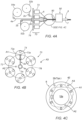
- a method for making a tubular body using a braiding apparatus comprising a primary mandrel source configured to direct a primary mandrel along a central axis, a plurality of horn gears rotatably mounted around the central axis in a predetermined arrangement such that the horn gears rotate about respective horn gear axes and carriers travel along a generally circular path around the central axis during operation of the braiding apparatus, and a secondary mandrel source configured to direct a secondary mandrel towards the primary mandrel from one of a plurality of locations comprising a first location disposed adjacent the central axis within the generally circular path, a second location aligned with a horn axis of one of the horn gears, and a third location outside the generally circular path.
- An outer jacket may be applied around the first and second portions of the primary mandrel and the secondary mandrel, and the primary mandrel may be removed to define a primary lumen within the tubular body.
- the secondary mandrel may be removed or may remain within the tubular body.
- a tubular device for a catheter or sheath comprising a proximal end and a distal end sized for introduction into a patient's body that includes a central lumen extending between the proximal and distal ends; an auxiliary lumen extending at least partially between the proximal and distal ends adj acent the central lumen; one or more reinforcement members comprising windings extending helically around the central lumen between the proximal and distal ends; and one or more layers surrounding the one or more reinforcement members, wherein the tubular device comprises a first portion in which at least some of the windings pass between the central and auxiliary lumens and at least some of the windings surround both the central and auxiliary lumens, and a second portion in which either a) all of the windings surround both the central and auxiliary lumens or b) all of the windings surround the central lumen and the auxiliary lumen is disposed outside the windings.
- an apparatus for performing a procedure within a patient's body that includes a tubular member comprising a proximal end, a distal end sized for introduction into a patient's body, a central axis extending therebetween, and a distal portion extending distally from an intermediate portion to the distal end; a primary lumen extending between the proximal and distal ends and surrounding at least a portion of the central axis; a steering element lumen extending at least partially between the proximal and distal ends adjacent the primary lumen; a steering element(s) slidably disposed within the steering element lumen(s) and comprising a distal end fixed to the tubular member distal end and a proximal end adjacent the proximal end of the tubular member; and an actuator on the proximal end coupled to the steering element proximal end such that, actuation of the actuator applies axial tension or compression to the steering element, thereby causing the distal
- One or more reinforcement members comprising windings may extend around the primary lumen between the proximal and distal ends, and one or more layers may surround the one or more reinforcement members, wherein the tubular member comprises a first portion in which at least some of the windings pass between the primary lumen and the steering element lumen and at least some of the windings surrounding both the primary lumen and the steering element lumen, and a second portion in which either a) all of the windings surround both the primary lumen and the steering element lumen or b) all of the windings surround the primary lumen and the steering element lumen is disposed outside the windings.
- an apparatus for performing a procedure within a patient's body that includes a tubular member comprising a proximal end, a distal end sized for introduction into a patient's body, a central axis extending therebetween, and a distal portion extending distally from an intermediate portion to the distal end; a primary lumen extending between the proximal and distal ends and surrounding at least a portion of the central axis; a steering element lumen extending at least partially between the proximal and distal ends adjacent the primary lumen; a steering element slidably disposed within the steering element lumen and comprising a distal end fixed to the tubular member distal end and a proximal end adjacent the proximal end of the tubular member; an actuator on the proximal end coupled to the steering element proximal end such that, actuation of the actuator applies axial tension or compression to the steering element, thereby causing the distal portion to bend; and a compression
- a tubular device for a catheter or sheath comprising a proximal end and a distal end sized for introduction into a patient's body, the tubular device including a lumen extending at least partially between the proximal and distal ends; a plurality of reinforcement members comprising windings extending helically around the lumen at least partially between the proximal and distal ends; and one or more layers surrounding the one or more reinforcement members, wherein the reinforcement members have a braiding configuration where at least one of a density and a pitch angle of the reinforcement members vary around a periphery of the lumen.
- the braiding configuration may include a relatively low density of strands of the reinforcement members around a first region of the periphery of the lumen and a relatively high density of strands of the reinforcement members a second region of the periphery and/or the strands around the first region may define a first pitch angle and the strands around the second region define a second pitch angle that is lower than the first pitch angle.
- a tubular device for a catheter or sheath comprising a proximal end and a distal end sized for introduction into a patient's body, the tubular device including a plurality of lumens extending at least partially between the proximal and distal ends; a plurality of reinforcement members comprising windings extending helically around the lumens at least partially between the proximal and distal ends; and one or more layers surrounding the one or more reinforcement members, wherein the reinforcement members have a braiding configuration where at least one of a density and a pitch angle of the reinforcement members vary around peripheries of the lumens.
- a method for making a tubular body using a braiding apparatus comprising a plurality of horn gears rotatably mounted around a central axis in a predetermined arrangement such that the horn gears rotate about respective horn gear axes and carriers travel along a generally circular path around the central axis during operation of the braiding apparatus.
- the method may include directing an elongate first mandrel through a first passage aligned with a first horn gear axis of a first horn gear of the horn gears towards the central axis; wrapping reinforcement members from the carriers around the first mandrel to create a braided assembly having a braiding configuration where at least one of a density and a pitch angle of the reinforcement members vary around a periphery of the first mandrel; and applying an outer jacket around the braided assembly to provide a tubular body.
- the braiding configuration may include a relatively low density of strands of the reinforcement members around a first region of the periphery of the first mandrel and a relatively high density of strands of the reinforcement members a second region of the periphery and/or the strands around the first region may define a first pitch angle and the strands around the second region define a second pitch angle that is lower than the first pitch angle.
- the method may include directing a plurality of elongate mandrels through passages aligned with horn gear axes of respective horn gears of the horn gears towards the central axis; wrapping reinforcement members from the carriers around the mandrels to create a braided assembly having a braiding configuration where at least one of a density and a pitch angle of the reinforcement members vary around a periphery of the mandrels; applying an outer jacket around the braided assembly to provide a tubular body; and removing the mandrels to define respective lumens within the tubular body.
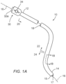
- the central lumen 18a may be sized for receiving or carrying a guide wire, procedure catheter, balloon catheter, ablation catheter, cardiac lead, needle, or other instrument (not shown), one or more wires or other conductors, one or more optical fibers, one or more tubes or accessory lumens, one or more mechanical elements, one or more sensors, and/or sized for delivering and/or removing fluids or other flowable agents or materials therethrough.
- the central lumen 18a may exit at or communicate with an outlet 17 in the distal end 14, e.g., to allow a guidewire or other instrument (not shown) to pass therethrough and/or for delivering or aspirating fluid therethrough.
- the central lumen 18a may be enclosed, e.g., terminating within or adjacent the distal end, e.g., by an electrode, cap, or other component (not shown) to isolate the central lumen 18a and/or elements carried therein from the environment outside the apparatus 10.
- the apparatus 10 in addition to the central lumen 18a, the apparatus 10 includes an auxiliary lumen 18b, e.g., extending adjacent the central lumen 18a, e.g., substantially parallel to and radially offset relative to the central axis 16.
- auxiliary lumen 18b may be a steering element lumen configured to receive a pull wire or other steering element 136 therein, e.g., to bend or otherwise deflect a distal portion of the catheter 110, as described further below.
- auxiliary lumen 218b may receive one or more wires or conductors 236 for coupling to one or more electrodes 238 mounted on the distal portion of the catheter 210, also as described further below.
- the apparatus 10 may include one or more additional lumens (not shown), e.g., one or more additional steering element lumens, conductor lumens, inflation lumens (e.g., if the apparatus 10 includes one or more balloons, not shown on the distal end 14), and/or accessory lumens.
- additional lumens e.g., one or more additional steering element lumens, conductor lumens, inflation lumens (e.g., if the apparatus 10 includes one or more balloons, not shown on the distal end 14), and/or accessory lumens.
- a pair of auxiliary lumens may be provided (not shown) on opposite sides of the apparatus 10, e.g., offset about one hundred eight degrees (180°) around the circumference of the apparatus 10.
- the auxiliary lumen(s) may have a variety of cross-sectional shapes and/or sizes, e.g., a substantially circular shape, an elliptical or oval shape, a substantially rectangular shape, a triangular shape, a pair of overlapping circles shape, and the like, e.g., similar to the devices disclosed in U.S. Publication No. 2014/ 0323964 , the entire disclosure of which is expressly incorporated by reference herein.
- the shape and/or size of the auxiliary lumen(s) may be substantially uniform along the length of the apparatus 10 or may vary at different locations, as described elsewhere herein.
- the proximal end 12 may include a handle or hub 30, e.g., configured and/or sized for holding and/or manipulating the apparatus 10 from the proximal end 12.
- the handle 30 may include one or more ports, e.g., port 32a communicating with the central lumen 18a, or other respective lumens (not shown).
- the port 32a may include one or more valves, e.g., a hemostatic valve (also not shown), which may provide a substantially fluid-tight seal, while accommodating insertion of one or more instruments or fluids into the central lumen 18a.
- the central lumen 18a is defined by an inner liner 40a including an inner surface 41a.
- the inner liner 40a may be formed from lubricious material, e.g., PTFE, to provide a lubricious inner surface 41a.
- the inner liner 40 may be formed from one or more layers of thermoplastic or other polymeric material including one or more coatings on the inner surface 41a having desired properties, e.g., a hydrophilic and/or lubricious coating, e.g., similar to the liners disclosed in U.S. Patent Nos. U.S. Patent Nos. 7,550,053 and 7,553,387 , and U.S. Publication No. 2009/ 0126862 , the disclosures of which are expressly incorporated by reference herein.
- a plurality of reinforcement members 43 may be braided around the inner liner 40a, e.g., with each reinforcement member 43 having the same material and/or shape.
- the reinforcement members 43 may have different sizes, materials, and/or shapes, e.g., a first size or shape extending helically in a first direction and a second size or shape (different than the first) extending helically in a second direction (e.g., opposite the first direction).
- FIG. 2 shows an example of a catheter 10A that includes a central lumen 18A-a that extends substantially along a central axis 16A and is surrounded by a reinforcement layer 42, which may be similar to any of the embodiments described elsewhere herein.
- the catheter 10A includes an auxiliary lumen 18A-b that extends between proximal and distal ends 12A, 14A of the catheter 10A adjacent the central lumen 18A-a at different radial and/or circumferential locations. As shown in FIG.
- the auxiliary lumen 18A-b may be braided into the reinforcement layer 42, while, as shown in FIG. 2B , at an intermediate portion, the auxiliary lumen 18A-b may transition outside the reinforcement layer 42. Further, as shown in FIG. 2C , the auxiliary lumen 18A-b may transition to a location closer to the central lumen 18A-a such that the reinforcement layer 42 surrounds both lumens 18A-a, 18A-b. Finally, as shown in FIG. 2D , the auxiliary lumen 18A-b may transition again and be braided into the reinforcement layer 42 along a distal portion to the distal end 14A.
- a deflectable catheter shaft may be constructed wherein one or more auxiliary lumens 18A-b (e.g., a single auxiliary lumen or two auxiliary lumens spaced approximately one hundred eighty degrees (180°) apart) may be braided into or within the reinforcement layer 42 as shown in FIG. 2D at an intermediate portion (e.g., corresponding to FIG. 2 sections B and/or C) while the auxiliary lumen 18A-b may transition outside the reinforcement layer 42 as shown in FIG. 2B at a distal and proximal location (e.g., corresponding to FIG. 2 sections A and D). Additionally, the auxiliary lumen(s) 18A-b may pass through a jacket layer (as described elsewhere herein) overlying the reinforcement layer at or near the point(s) of transition from within to outside of the reinforcement layer 42.
- auxiliary lumen(s) 18A-b may pass through a jacket layer (as described elsewhere herein) overlying the reinforcement layer at or near the point(s) of transition from within to
- Locating the second segment 118b-2 surrounded by the reinforcement layer 142 may enhance performance properties of the steering element 136 and/or may reduce the risk of the steering element 136 tearing through the wall of the distal portion 124, e.g., when a proximal force or tension is applied to the steering element 136.
- Locating the first segment 118b-1 outside the reinforcement layer 142 may facilitate accessing the auxiliary lumen 118b, e.g., during manufacturing and/or assembly, to couple the proximal end of the steering element 136 to an actuator and/or other components (not shown) at the proximal end of the apparatus 110.
- the location of the second segment 118b-2 of the auxiliary lumen 118b may extend from a proximal end of the apparatus 110 to a distal portion and then may transition to the location of the first segment 118b-1, e.g., outside the reinforcement layer 142 along the distal portion.
- the apparatus 50 and methods herein may be used to make one or more relatively long tubular bodies 8, e.g., that are substantially longer than finished catheters or other tubular devices.
- one resulting tubular body 8 may be collected, e.g., on a take-up reel or container (not shown), or may be separated into individual shorter tubular bodies, e.g., using a cutter or other tool (not shown), that may be incorporated into individual catheters or other tubular devices, e.g., as described elsewhere herein and/or as disclosed in U.S. Publication No. 2009/ 0126862 , the entire disclosure of which is expressly incorporated by reference herein.
- the apparatus 50 may include one or more sources 52 of mandrels 2 and, optionally, one or more sources 54 of liner material 4, which may be fed into a guide 60 to define lumens of the tubular bodies 8.
- a first reel 52a may include an elongate primary mandrel 2a, e.g., shaped and/or configured to define a primary or central lumen (not shown) of the tubular bodies 8.
- a second reel 52b may include an elongate auxiliary mandrel 2b, e.g., shaped and/or configured to define a secondary or auxiliary lumen (also not shown) of the tubular bodies 8.
- the second reel 52b or other source of auxiliary mandrel may be located at one of a plurality of available locations during operation to configure the tubular bodies 8 in a desired manner.
- one or more additional auxiliary mandrels may be provided (not shown), which may also be moved to one or more locations.
- a heater within a co-extruder may melt or otherwise soften the jacket material 7 to allow the jacket material 7 to flow around the reinforcement members 43 and into contact with the liner material 4 surrounding the mandrels 2 (or the mandrels 2 directly if no liner material is provided).
- the jacket material 7 may be a thermoset plastic or other material such that components of the jacket material 7 may be delivered into the co-extruder, e.g., as a liquid, powder, and the like, and mixed to form a slurry that is delivered around the reinforcement-wrapped mandrels 2.
- the resulting tubular body 8 (with or without jacket material 7) may be collected, e.g., on a capture reel or in a container (not shown). Thereafter, the tubular body 8 may be further processed to make a catheter, sheath, or other device. For example, a cutter or other tool (not shown) may separate the tubular body 8 into individual tubular shafts, e.g., before or after removing the mandrels 2.
- a cutter or other tool may separate the tubular body 8 into individual tubular shafts, e.g., before or after removing the mandrels 2.
- the mandrels 2 may remain within the tubular body 8 when cut into individual devices, and then may be removed, resulting in a primary lumen and an auxiliary lumen, e.g., similar to the apparatus 10 shown in FIG. 1B .
- the mandrels 2 may be removed before the tubular body 8 is cut into individual devices.
- a steering element 136 may be inserted through the auxiliary lumen 118b (created when the auxiliary mandrel 2b is removed).
- the auxiliary mandrel 2b may remain within the tubular device to provide the steering element, e.g., if the friction between the outer surface of the auxiliary mandrel 2b and the liner or other material defining the auxiliary lumen are relatively low.
- a tip or other component may be attached to a distal end 114 of the apparatus 110, e.g., after attaching the distal end 136b of the steering element 136 to the tip.
- the other end of the steering element may be coupled to an actuator of a handle attached to a proximal end of the tubular device, e.g., similar to the embodiment shown in FIG. 1A and described elsewhere herein.
- the auxiliary lumen 218b may be formed by positioning the auxiliary mandrel 2b in location A2 (shown in FIGS. 4B and 4C or optionally in location A1 for at least some portions) and generally braiding the reinforcement material 6 around both the primary and auxiliary mandrels 2a, 2b, except that at the segments corresponding to the locations of the electrodes 238, the auxiliary mandrel 2b may be moved to location A3 and then returned back to location A2 (or A1). After the outer layer 244 has been applied around the reinforcement members 242, the mandrels may be removed to provide an auxiliary lumen with segments 218b-1 braided into or under the reinforcement layer 242 other than segments 218b-2 at the electrode locations.
- One or more wires 236 may be directed into the auxiliary lumen 218b (or may be used as the auxiliary mandrel, if desired), and the segments 218b-2 may be accessed, e.g., by cutting into the outer layer 244 to expose the wire(s), which may then be coupled to the electrodes 238 mounted on the apparatus 210.
- the auxiliary mandrel 2b may remain at location A2 (or A1) for the entire length of the tubular body 8, and a segment of the auxiliary mandrel 2b may be manually (or automatically) pulled out from within the braid of the reinforcement members 6, as shown in FIG. 7A before applying the outer layer 244.
- the auxiliary lumen 318b may be discontinuous, i.e., communicating with side openings 319.
- One or more wire(s) may be directed into the auxiliary lumen 318b such that regions of the wire(s) exit and reenter the side openings 319. These regions may then be exposed and/or otherwise coupled to an electrode (not shown) mounted on the apparatus 310.
- the secondary mandrels 2b are braided into the reinforcement members 643, e.g., such that some of the members 643 are disposed between the primary and secondary mandrels 2a, 2b, and some members surround both the primary and secondary mandrels 2a, 2b, as shown in FIG. 10A .
- the secondary mandrels 2b transition such all of the reinforcement members 643 are braided around only the primary mandrel 2a, as shown in FIG. 10B . Braiding of the reinforcement members 643 may continue beyond the ends of the secondary mandrels 2b, e.g., as shown in FIG. 10C .
- One or more outer layers may then be applied around the subassembly 640 to provide the final catheter 610.
- a plurality of tubular jackets 650 may be applied around the subassembly 640, e.g., having different materials and/or mechanical properties, as desired for the different portions of the catheter 610.
- the jackets 650 may be sized to have the subassembly 640 inserted into them such that they abut or are otherwise disposed adjacent one another around the subassembly 640.
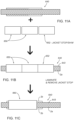
- a tubular jacket and/or shim 652 may be positioned around the subassembly 640, e.g., around the portion 640b such that the shim 652 at least partially covers the unconstrained ends of the secondary mandrels 2b.
- the resulting assembly 660 may be reflowed, heated, and/or otherwise laminated, e.g., similar to other embodiments described elsewhere herein.
- the shim 652 may then be removed, as shown in FIG. 11C , and then the mandrels 2b may also be removed, as shown in FIGS. 11D and 11E .
- a shoulder 664 (at the right of the assembly 660) remains at the junction between the tubular jackets 650 and the removed shim 652 with the lumens 616b created by removal of the secondary mandrels 2b exiting from the face of the shoulder 664 in a position radially outward from the reinforcement members 643 present in the portion 640b.
- a pull wire ring 638 having pull wires 636 extending from its proximal edge may then be inserted over the portion 640b with the pull wires 636 may be loaded into the lumens 616b.
- distal ends 636b of the pull wires 636 may be attached to the proximal edge of the ring 638, e.g., by welding, soldering, bonding with adhesive, and the like before the ring 638 is inserted over the portion 640b.
- This allows the pull wires 636 to be inserted into the auxiliary lumens 616b (not shown in FIG. 11F ; see, e.g., FIG. 11E ) without taking a substantial bend and the pull wire ring 638 may abut the shoulder 664.
- the reinforcement members 643 may then be trimmed at or near the distal edge of the pull wire ring 638 with the pull wire ring constraining the reinforcement members 643 such that, as shown in FIG. 11I , a subsequent a jacket and or tip may be bonded, laminated, reflowed or otherwise attached over and/or beyond the pull wire ring 638 without risk of the reinforcement members 643 rising to or protruding through the surface.
- tip defects may be minimized, stress on the pull wire may be minimized, and/or the assembly may be otherwise considerably improved.
- the pull wire ring 638 may include one or more features (e.g., holes, slots, etc. not shown) to enhance attachment to the catheter shaft, tip, etc.
- a thermoplastic liner e.g., with a coating, similar to other embodiments herein
- Configuring the ring 638 and/or tip jacket components in this manner may provide one or more advantages. For example, lapping the braid or reinforcement layer into and through the ring 638 may eliminate a common kink point that may be a limitation with current devices. In addition, this configuration may eliminate problems with cut end wire protrusions as they are full constrained within the ring 638. In addition, this configuration may provide locations for pull wire lumens that substantially align with desired positions of pull wires, which may ease assembly, enhance integrity of the tip, and/or improve alignment of pull forces.
- FIGS. 12-13 another exemplary embodiment of a steerable catheter 708 is shown that generally includes a tubular body or shaft 710 including a proximal end 712, a distal end 714 sized for introduction into a patient's body, and one or more lumens 718 extending therebetween, which may be constructed using similar materials and methods as other embodiments described herein. For example, as shown in FIGS.
- the tubular body 710 may include a primary lumen 718a and one or more auxiliary lumens, e.g., a steering element lumen 718b offset from a central longitudinal axis 716 of the tubular body 710, e.g., close to the outer periphery of the tubular body 710, that slidably receives a pull wire or other steering element 736.
- auxiliary lumens e.g., a steering element lumen 718b offset from a central longitudinal axis 716 of the tubular body 710, e.g., close to the outer periphery of the tubular body 710, that slidably receives a pull wire or other steering element 736.
- a handle or hub 730 may be provided on the proximal end 712 of the tubular body 710, e.g., including one or more ports 732 communicating with the central lumen 718a or other respective lumens (not shown).
- port 732a may include one or more valves, e.g., a hemostatic valve (not shown), which may provide a substantially fluid-tight seal, while accommodating insertion of one or more instruments or fluids into the central lumen 718a.
- a side port 732b may also be provided, e.g., for delivering fluid into and/or aspirating fluid from the primary lumen 718a, e.g., around an instrument inserted into the primary lumen 718a.
- the handle 730 may include one or more actuators, such as sliders, buttons, switches, rotational actuators, and the like, e.g., for activating and/or manipulating components (also not shown) on the distal end 714 or otherwise operating the catheter 708.
- actuators such as sliders, buttons, switches, rotational actuators, and the like, e.g., for activating and/or manipulating components (also not shown) on the distal end 714 or otherwise operating the catheter 708.
- an actuator 734 may be provided that is coupled to a proximal end 736a of the steering element 736 disposed within the auxiliary lumen 718b, e.g., similar to other embodiments described elsewhere herein.
- the steering element 736 may be actuated, e.g., axially pushed or pulled, to apply a bending force to a distal portion 724 of the tubular body 710, e.g., to cause the distal portion 724 to curve, bend, or otherwise deflect in a desired manner.
- a compression-resistant element 746 is disposed within the steering element lumen 718b surrounding or otherwise adjacent at least a portion of the steering element 736, e.g., extending from the proximal end 712a of the tubular body 710 through an intermediate portion 722, i.e., terminating at the distal portion 724, to prevent forces from the steering element 736 from transferring to the tubular body 710 proximal to the distal portion 724.
- an intermediate portion 722 i.e., terminating at the distal portion 724
- the compression-resistant element 746 may be sized to slide within the steering element lumen 718b and/or slidably receive the steering element 736 therethrough, e.g., thereby preventing bending forces from the steering element 736 being transferred to the tubular member material surrounding the steering element lumen 718b along portion(s) where the compression-resistant element 746 is provided.
- the compression-resistant element 746 may be a tightly-wound coil, e.g., with coils abutting one another in a relaxed or low potential energy state, such that the coil cannot be compressed axially.
- the coil 746 may be formed from metal, steel, polymers, or composite materials, e.g., one or more stainless steel or Nitinol wires having a round or rectangular cross-section.
- other tubular or cylindrical structures may be provided for the compression-resistant element 746, which may be slidably received within the steering element lumen 718b and slidably receive the steering element 736 therethrough.
- the compression-resistant element 746 may include a counter-wound coil tube, a coil tube with one or more attached tensile elements, a laser cut tube, a densely braided polymer tube, and the like (all not shown).
- the coil 746 may be free floating or otherwise slidably received within the steering element lumen 718b, e.g., with proximal and distal ends 746a, 746b thereof remaining uncoupled to the tubular body 710.
- one or both ends may be fixed or stopped relative to the tubular body 710, e.g., by one or more of embedding the end(s) within the tubular body, bonding with adhesive, heat welding, sonic welding, incorporation of a secondary stop element, and the like.
- the coil may be fixed at its distal end with an additional stop for reinforcement whereas the proximal end may be left free to slide both along the length and into and out of the steering element lumen such that path length changes of the steering element lumen due to manipulation of the catheter may be accommodated without transferring these forces to the tubular body 710.
- FIG. 13B shows the distal end 746b of the coil 746 fixed relative to the tubular body 710.
- the proximal end 746a of the coil 746 may be free to move within the handle 730 while still coupled to the actuator 734.
- the coil 746 may include a loop or helical section (not shown) within the interior of the handle 730, e.g., around the primary lumen shaft, i.e., between the proximal end 712 of the tubular body 710 and where the proximal end 746 is coupled to the handle 730 adjacent the actuator 734.
- the proximal end 736a of the steering element 736 may exit the fixed proximal end 746a of the coil 746 and then be coupled to the actuator 734.
- both ends of the coil 746 are fixed relative to the tubular body 710 (while the intermediate length is free to slide within the steering element lumen 718b, the coil 746 may resist axial extension as well as compression along the side of the tubular body 710 surrounding the steering element lumen 718b.
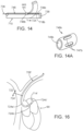
- FIG. 14A shows an exemplary embodiment of a stop 748b that includes a passage 749b therethrough for slidably receiving the steering element 736, e.g., such that the steering element 736 may continue through the distal portion 724 to a ring or other anchor 738 on the distal end 714 of the tubular body 710, e.g., as shown in FIGS. 13C, 13D , and 14 .
- the stop 748b may be sized such that the distal end 746b of the coil 746 may abut or otherwise contact the stop 748b, e.g., when the region adjacent the steering element lumen 718b is axially compressed in bending, as explained further elsewhere herein.
- the stop 748b also includes a plurality of recesses 747b around its perimeter, which may facilitate embedding or otherwise securing the stop 748b across the steering element lumen 718b.
- the stop 748b may be placed adjacent the steering element lumen 718b and jacket material may be applied around the stop 748b and heated or otherwise caused to flow into the recesses 747b to secure the stop 748b in place.
- the distal end 746b of the coil 746 may be coupled to the stop 748b, e.g., by one or more of bonding with adhesive, welding, fusing, heat welding, and the like. Otherwise, the length of the coil 746 may be set such that the distal end 746b contacts or is spaced away from the distal stop 748b when the tubular body 710 is a desired orientation, e.g., substantially straight.
- a proximal stop 748a may be provided, e.g., within the handle 730, as shown in FIG. 12 , or alternatively, within a proximal portion 720 of the tubular body 710 (not shown).
- the proximal end 746a of the coil 746 may be separate from the proximal stop 748a, e.g., such that the proximal end 746a contacts or is spaced away from the proximal stop 748a, or the proximal end 746a may be coupled to the proximal stop 748a, as desired.
- the compression-resistant element 746 is shown extending entirely from the handle 740, through the proximal and intermediate portions 720, 722 of the tubular body 710 (terminating before the distal portion 724), it will be appreciated that the compression-resistant element 746 may have different lengths and/or configurations, e.g., extending proximally only partially from the intermediate portion 722 towards the proximal portion 720, e.g., if the proximal portion 720 is constructed to be resistant to bending. In addition or alternatively, multiple compression-resistant elements may be provided at different locations along the length of the tubular body 710 to provide desired bending characteristics.
- the distal portion 724' includes a first portion 724a' that does not include a compression-resistant element, a second portion 724b' distal to the first portion 724a' that includes a compression-resistant element (not shown), and a third portion 724c' distal to the second portion 724b' that does not include a compression-resistant element.
- the catheter 708 may include an inner liner 740, e.g., at least partially or entirely surrounding or otherwise defining the central lumen 718a and/or including one or more coatings, a reinforcement layer 742 surrounding the inner liner 740, and an outer jacket 744 surrounding and/or encasing the reinforcement layer 742, e.g., as identified in FIG. 13A .
- the reinforcement layer 742 and/or outer jacket 744 may be attached to the inner liner 740, e.g., by laminating, adhering, adhesive bonding, ultrasonic welding, reflowing or other heating, and the like, as described elsewhere herein.
- an inner liner (not shown) may also at least partially surround the steering element lumen 718b, which may be formed from a lubricious material and/or may include one or more coatings on its inner surface, similar to the inner liner 740.
- one or more of the layers of the tubular body 710 may have a substantially homogenous construction between the proximal and distal ends 712, 714.
- the construction may vary along the length of the tubular body 710 to provide desired properties, e.g., between the proximal, intermediate, and distal portions 720, 722, 724.
- the proximal portion 720 adjacent the proximal end 712 may be substantially rigid or semi-rigid, e.g., providing sufficient column strength to allow the distal end 714 of the tubular body 710 to be pushed or otherwise manipulated from the proximal end 712, while the distal portion 724 may be substantially flexible.
- the reinforcement layer 742 may include a plurality of, round or flat wires, filaments, strands, or other reinforcement members, e.g., formed from metal, such as stainless steel, plastic, such as PEEK, glass, woven or twisted fibers, such as aramid, and the like, or composite materials.
- the location of the reinforcement layer 742 may vary relative to the central lumen 718a and/or steering element 718b.
- FIGS. 13A-13D show that the steering element lumen 718b may be braided into the reinforcement layer 742 along the proximal, intermediate, and distal portions 720-724 of the tubular body 710.
- the steering element lumen 718b may transition outside the reinforcement layer 742.
- the steering element lumen 718b may transition outside the reinforcement layer 742 (not shown), to facilitate accessing the steering element lumen 718b, e.g., to insert and/or otherwise couple the steering element 746 to the actuator 734, similar to other embodiments herein.
- the tubular body 710 may be fabricated using similar methods and materials as other embodiments described herein.
- a primary mandrel 2a and liner material 4a may be fed along the braiding apparatus configured to define the central lumen 718a (after the mandrel 4a is removed) and elements 6 may be braided around the primary mandrel 4a to provide the reinforcement layer 742.
- a secondary mandrel 2b may be fed adjacent the primary mandrel 2a, e.g., optionally, with a secondary liner (not shown) configured to define the steering element lumen 718b.
- the elements 6 of the reinforcement layer 742 may pass over and under the secondary mandrel 2b, thereby braiding the secondary mandrel 2B (and the resulting steering element lumen 718b) into the reinforcement layer 742.
- Jacket material 7 may be applied around the wrapped assembly, e.g., to provide one or multiple tubular bodies 8, similar to other embodiments herein.
- a length of the tubular body material 8 may be provided and, after removing the secondary mandrel in the steering element lumen 718b, the compression-resistant element 746 may be inserted into the lumen 718b and positioned at the desired location.
- a steering element may also be inserted into the lumen 718b, e.g., through the compression-resistant element 746.
- Additional components e.g., the handle 730, stops 748, one or more tip segments (not shown) may then be added to the assembly, as desired to provide a finished catheter 708, e.g., similar to that shown in FIG. 12 .
- other components e.g., one or more sensing elements, electrodes, and the like, may be added to the catheter as desired, similar to other embodiments herein.
- the compression-resistant element 746 may be introduced into the tubular body during the braiding process.
- a coil may be created, e.g., using the spinning action of a horn gear (e.g., one of horn gears 72) and/or driving a coiling apparatus positioned through or along the central axis of one of the horn gears, a tightly-wound coil may be formed and fed around the secondary mandrel 2b or may be used instead of the secondary mandrel 2b.
- a formed coil may be fed around the secondary mandrel 2b (or instead of the secondary mandrel 2b).
- a coil pulled into the assembly may include a permanent or temporary tensile element to avoid expansion of the coil during assembly.
- liner material may be wrapped directly around the coil material or a spacer or shim may be provided around or adjacent the coil material, e.g., similar to other embodiments herein.
- material for the steering element may also be fed into the assembly, e.g., within the coil material such that the steering element and compression-resistant element components may be fed substantially continuously along with the other components of the tubular body.
- one or more friction reducing elements may also be fed or applied during assembly, e.g., one or more liners, coatings, and the like (not shown), applied to reduce friction between the steering element and the compression-resistant element and/or between the compression-resistant element and the inner wall of the steering element lumen.
- additional mandrels and/or components may be fed simultaneously using the braiding apparatus.
- it may be desired to include multiple steering element lumens, e.g., spaced apart from one another around the periphery of the tubular body.
- it may be desired to include one or more additional auxiliary lumens and/or primary lumens.
- the embedded braid may allow for semi-automated incorporation of the steering element actuation lumen(s) into the cross-section of the catheter, as well as providing easy access along the length for various purposes (e.g., bonding of push/pull wire, distal fixation of the flexible compression element, access in the handle to bring the steering element to the handle actuator, etc.).
- the compression-resistant element may be free-floating within a supporting lumen to allow it to equilibrate forces at all points. In some cases where necessary it may include a reservoir where "saved" compression element length may be taken or added as need to accommodate large path length changes.
- the distal tip region856 may have a substantially uniform diameter cylindrical shape, which, optionally, may include a rounded, tapered, or other substantially atraumatic shape (not shown), e.g., to facilitate advancement of the catheter 808 within a patient's body (not shown).
- disparate pitches within a single braid element may be constructed by braiding at least one permanent (like a cable or a filament) or temporary (like a mandrel for purpose of creating a lumen) element in an axially loaded configuration (through the braid horn gears).
- the "pitch angle" (between wire angle and main axis) of the braid will, of necessity, be larger over the circumference of the axially loaded element.
- the pitch angle of the braid may be relatively small in regions where either 1) the braided axis/regions from the horn gears without any axial elements loaded, or 2) the braided axis/regions from the horn gears with axially loaded elements that are smaller in diameter as compared to the other axially loaded elements.
- multiple elements may be put through multiple horn gears to create patterns of kink resistant cores and/or compression resistant cores.
- this configuration may provide varying pitch angles around the peripheries of the mandrels.
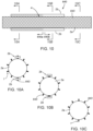
- the low density region of the reinforcement elements 1007a may define relative high pitch angles, e.g., having properties similar to a coil
- the high density region 1007b may define relatively low braid angles, e.g., similar to a braided cable, thereby providing both flexibility/kink resistant properties and compression/extension resistant properties to the resulting tubular body.
- FIG. 19B the low density region of the reinforcement elements 1007a may define relative high pitch angles, e.g., having properties similar to a coil
- the high density region 1007b may define relatively low braid angles, e.g., similar to a braided cable, thereby providing both flexibility/kink resistant properties and compression/extension resistant properties to the resulting tubular body.
- FIG. 19B the low density region of the reinforcement elements 1007a may define relative high pitch angles, e.g., having properties similar to a coil
- the high density region 1007b may define relatively low
- FIG. 21 exemplary braiding configuration of reinforcement elements braided around three primary mandrels 1022, which may be fed through passages of horn gears that are spaced equally apart around the braiding apparatus (not shown).
- the density of the reinforcement elements 1027a may be lower around the outer peripheries of the mandrels 1022 and may be higher at the region 1027b between the mandrels 1022.
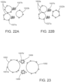
- FIGS. 22A and 22B show alternative configurations of braiding patterns around three mandrels 1022 where two of the mandrels 1022a are closer to one another than the third mandrel 1022b.
- the first mandrels 1022a may be fed through adjacent horn gears (adjacent to one another around the circle of the braiding apparatus) with the second mandrel 1022b fed through a horn gear opposite the adjacent horn gears.
- the mandrels 1002-1022 may be fed through the horn gears and reinforcement elements 1007-1027 may be braided around them without any other mandrels or supports.
- reinforcement elements may cause the mandrel(s) to automatically center and/or stay in a substantially constant radial position, e.g., relative to the central axis 71 of the braiding apparatus.
- one or more cables or other relatively small elongate elements may be fed from other horn gears, i.e., other than the horn gears through which the primary mandrel(s) are fed.
- FIG. 23 shows an exemplary embodiment of an exemplary braiding configuration of reinforcement elements 1007 braided around two primary mandrels 1002 spaced apart from relatively small secondary mandrels 1009. Similar to the configuration shown in FIG. 19A , the mandrels 1002 may be fed through passages 73a in opposite horn gears 72a, e.g., as shown in FIG. 18 .
- the lumens formed by the mandrels used in the methods described herein may not extend along the entire length of the resulting tubular bodies.
- a mandrel may be positioned such it is braided into the reinforcement members along a first portion and then the mandrel may be repositioned to remove it entirely outside the area of the reinforcement members and jacket material.
- the steering element lumen 718a may extend from the distal end 714 of the tubular body 710 towards the proximal end 712, but exit before reaching the proximal end 712, e.g., at a side opening 713.
- a mandrel for the steering element lumen 718b may be braided into the reinforcement layer 742 from the distal end 724 to the location of the side opening 713, whereupon the mandrel may be repositioned outside the braid circle of the braiding apparatus such that the mandrel is not braided or encased in jacket material.
- the mandrel may be removed to provide the steering element lumen 718b and side opening 713.
- one or more lumens may be formed that extend only partially along the length of a tubular member, e.g., from one end to an intermediate location or between two intermediate locations spaced from both ends. Such lumens may be braided into the reinforcement layer along at least a portion of their lengths and/or may be positioned at different locations relative to the reinforcement layer and/or outer jacket, e.g., using the methods described herein.
Landscapes
- Health & Medical Sciences (AREA)
- Life Sciences & Earth Sciences (AREA)
- Engineering & Computer Science (AREA)
- Anesthesiology (AREA)
- Heart & Thoracic Surgery (AREA)
- Veterinary Medicine (AREA)
- Biophysics (AREA)
- Pulmonology (AREA)
- Public Health (AREA)
- Biomedical Technology (AREA)
- General Health & Medical Sciences (AREA)
- Hematology (AREA)
- Animal Behavior & Ethology (AREA)
- Mechanical Engineering (AREA)
- Chemical & Material Sciences (AREA)
- Composite Materials (AREA)
- Media Introduction/Drainage Providing Device (AREA)
Applications Claiming Priority (4)
| Application Number | Priority Date | Filing Date | Title |
|---|---|---|---|
| US201562201319P | 2015-08-05 | 2015-08-05 | |
| US201562250133P | 2015-11-03 | 2015-11-03 | |
| EP16833985.1A EP3331595B1 (de) | 2015-08-05 | 2016-08-05 | Kathetervorrichtungen und verfahren zur herstellung davon |
| PCT/US2016/045922 WO2017024289A1 (en) | 2015-08-05 | 2016-08-05 | Catheter devices and methods for making them |
Related Parent Applications (1)
| Application Number | Title | Priority Date | Filing Date |
|---|---|---|---|
| EP16833985.1A Division EP3331595B1 (de) | 2015-08-05 | 2016-08-05 | Kathetervorrichtungen und verfahren zur herstellung davon |
Publications (2)
| Publication Number | Publication Date |
|---|---|
| EP4397265A2 true EP4397265A2 (de) | 2024-07-10 |
| EP4397265A3 EP4397265A3 (de) | 2024-11-13 |
Family
ID=57943726
Family Applications (2)
| Application Number | Title | Priority Date | Filing Date |
|---|---|---|---|
| EP24164563.9A Pending EP4397265A3 (de) | 2015-08-05 | 2016-08-05 | Kathetervorrichtung und verfahren zu ihrer herstellung |
| EP16833985.1A Active EP3331595B1 (de) | 2015-08-05 | 2016-08-05 | Kathetervorrichtungen und verfahren zur herstellung davon |
Family Applications After (1)
| Application Number | Title | Priority Date | Filing Date |
|---|---|---|---|
| EP16833985.1A Active EP3331595B1 (de) | 2015-08-05 | 2016-08-05 | Kathetervorrichtungen und verfahren zur herstellung davon |
Country Status (2)
| Country | Link |
|---|---|
| EP (2) | EP4397265A3 (de) |
| WO (1) | WO2017024289A1 (de) |
Families Citing this family (4)
| Publication number | Priority date | Publication date | Assignee | Title |
|---|---|---|---|---|
| US11173285B2 (en) * | 2018-06-28 | 2021-11-16 | Biosense Webster (Israel) Ltd. | Producing a guidewire comprising a position sensor |
| KR20210096130A (ko) * | 2018-11-27 | 2021-08-04 | 뉴웨이브 메디컬, 인코포레이티드 | 에너지 전달을 위한 내시경 시스템 |
| EP4188679A1 (de) * | 2020-07-31 | 2023-06-07 | Medtronic, Inc. | Verfahren und system zur generativen fertigung von medizinischen vorrichtungen mit interner formung |
| EP4370188A1 (de) * | 2021-07-12 | 2024-05-22 | Boston Scientific Scimed Inc. | Radial getakteter steuerbarer katheter |
Citations (4)
| Publication number | Priority date | Publication date | Assignee | Title |
|---|---|---|---|---|
| US20090126862A1 (en) | 2007-10-19 | 2009-05-21 | Leeflang Stephen A | Strip lined catheters and methods for constructing and processing strip lined catheters |
| US7550053B2 (en) | 2006-01-26 | 2009-06-23 | Ilh, Llc | Catheters with lubricious linings and methods for making and using them |
| US7553387B2 (en) | 2005-10-04 | 2009-06-30 | Ilh, Llc | Catheters with lubricious linings and methods for making and using them |
| US20140323964A1 (en) | 2013-03-16 | 2014-10-30 | Clph, Llc | Steerable catheters and methods for making them |
Family Cites Families (7)
| Publication number | Priority date | Publication date | Assignee | Title |
|---|---|---|---|---|
| WO1994010897A1 (en) * | 1992-11-17 | 1994-05-26 | Omega Universal Limited | Deflectable medical instrument |
| US5431168A (en) * | 1993-08-23 | 1995-07-11 | Cordis-Webster, Inc. | Steerable open-lumen catheter |
| US7998112B2 (en) * | 2003-09-30 | 2011-08-16 | Abbott Cardiovascular Systems Inc. | Deflectable catheter assembly and method of making same |
| US9833595B2 (en) | 2005-12-30 | 2017-12-05 | Biosense Webster, Inc. | Dual-lever bi-directional handle |
| US7833218B2 (en) * | 2007-04-17 | 2010-11-16 | Medtronic Vascular, Inc. | Catheter with reinforcing layer having variable strand construction |
| CN104853797A (zh) * | 2012-09-27 | 2015-08-19 | 斯瑞克公司 | 制造可变地加强的长形医疗装置的方法 |
| CN110898312B (zh) * | 2013-12-20 | 2022-11-15 | 波士顿科学国际有限公司 | 集成导管系统 |
-
2016
- 2016-08-05 WO PCT/US2016/045922 patent/WO2017024289A1/en not_active Ceased
- 2016-08-05 EP EP24164563.9A patent/EP4397265A3/de active Pending
- 2016-08-05 EP EP16833985.1A patent/EP3331595B1/de active Active
Patent Citations (4)
| Publication number | Priority date | Publication date | Assignee | Title |
|---|---|---|---|---|
| US7553387B2 (en) | 2005-10-04 | 2009-06-30 | Ilh, Llc | Catheters with lubricious linings and methods for making and using them |
| US7550053B2 (en) | 2006-01-26 | 2009-06-23 | Ilh, Llc | Catheters with lubricious linings and methods for making and using them |
| US20090126862A1 (en) | 2007-10-19 | 2009-05-21 | Leeflang Stephen A | Strip lined catheters and methods for constructing and processing strip lined catheters |
| US20140323964A1 (en) | 2013-03-16 | 2014-10-30 | Clph, Llc | Steerable catheters and methods for making them |
Also Published As
| Publication number | Publication date |
|---|---|
| EP3331595A4 (de) | 2019-05-01 |
| EP3331595A1 (de) | 2018-06-13 |
| EP3331595B1 (de) | 2024-03-20 |
| WO2017024289A1 (en) | 2017-02-09 |
| EP4397265A3 (de) | 2024-11-13 |
Similar Documents
| Publication | Publication Date | Title |
|---|---|---|
| US11951262B2 (en) | Catheter devices and methods for making them | |
| US11850375B2 (en) | Catheter devices and methods for making them | |
| US10406319B2 (en) | Steerable catheters and methods for making them | |
| US11116938B2 (en) | Electrode catheters and methods for making them | |
| US10065015B2 (en) | Catheter devices and methods for making them | |
| EP3215209B1 (de) | Kathetervorrichtungen und verfahren zur herstellung davon | |
| EP3331595B1 (de) | Kathetervorrichtungen und verfahren zur herstellung davon | |
| US20220072269A1 (en) | Catheters and methods for making them | |
| US12616816B2 (en) | Catheter devices and methods for making them | |
| US20250001134A1 (en) | Single-part deflectable catheter devices and methods for making them | |
| EP3139988B1 (de) | Elektrodenkatheter und verfahren zur herstellung davon |
Legal Events
| Date | Code | Title | Description |
|---|---|---|---|
| PUAI | Public reference made under article 153(3) epc to a published international application that has entered the european phase |
Free format text: ORIGINAL CODE: 0009012 |
|
| STAA | Information on the status of an ep patent application or granted ep patent |
Free format text: STATUS: THE APPLICATION HAS BEEN PUBLISHED |
|
| AC | Divisional application: reference to earlier application |
Ref document number: 3331595 Country of ref document: EP Kind code of ref document: P |
|
| AK | Designated contracting states |
Kind code of ref document: A2 Designated state(s): AL AT BE BG CH CY CZ DE DK EE ES FI FR GB GR HR HU IE IS IT LI LT LU LV MC MK MT NL NO PL PT RO RS SE SI SK SM TR |
|
| REG | Reference to a national code |
Ref country code: DE Ref legal event code: R079 Free format text: PREVIOUS MAIN CLASS: A61B0018140000 Ipc: A61M0025010000 |
|
| PUAL | Search report despatched |
Free format text: ORIGINAL CODE: 0009013 |
|
| AK | Designated contracting states |
Kind code of ref document: A3 Designated state(s): AL AT BE BG CH CY CZ DE DK EE ES FI FR GB GR HR HU IE IS IT LI LT LU LV MC MK MT NL NO PL PT RO RS SE SI SK SM TR |
|
| RIC1 | Information provided on ipc code assigned before grant |
Ipc: A61B 18/14 20060101ALI20241007BHEP Ipc: B29C 70/30 20060101ALI20241007BHEP Ipc: A61M 25/00 20060101ALI20241007BHEP Ipc: A61M 25/01 20060101AFI20241007BHEP |
|
| STAA | Information on the status of an ep patent application or granted ep patent |
Free format text: STATUS: REQUEST FOR EXAMINATION WAS MADE |
|
| 17P | Request for examination filed |
Effective date: 20250512 |
|
| STAA | Information on the status of an ep patent application or granted ep patent |
Free format text: STATUS: EXAMINATION IS IN PROGRESS |