EP4397340A2 - Kappenvorrichtungen, systeme und verfahren für flüssigkeitsabgabevorrichtungen - Google Patents
Kappenvorrichtungen, systeme und verfahren für flüssigkeitsabgabevorrichtungen Download PDFInfo
- Publication number
- EP4397340A2 EP4397340A2 EP24162212.5A EP24162212A EP4397340A2 EP 4397340 A2 EP4397340 A2 EP 4397340A2 EP 24162212 A EP24162212 A EP 24162212A EP 4397340 A2 EP4397340 A2 EP 4397340A2
- Authority
- EP
- European Patent Office
- Prior art keywords
- liquid delivery
- sensor
- delivery device
- cap device
- cap
- Prior art date
- Legal status (The legal status is an assumption and is not a legal conclusion. Google has not performed a legal analysis and makes no representation as to the accuracy of the status listed.)
- Pending
Links
Images


Classifications
-
- A—HUMAN NECESSITIES
- A61—MEDICAL OR VETERINARY SCIENCE; HYGIENE
- A61M—DEVICES FOR INTRODUCING MEDIA INTO, OR ONTO, THE BODY; DEVICES FOR TRANSDUCING BODY MEDIA OR FOR TAKING MEDIA FROM THE BODY; DEVICES FOR PRODUCING OR ENDING SLEEP OR STUPOR
- A61M5/00—Devices for bringing media into the body in a subcutaneous, intra-vascular or intramuscular way; Accessories therefor, e.g. filling or cleaning devices, arm-rests
- A61M5/178—Syringes
- A61M5/31—Details
- A61M5/315—Pistons; Piston-rods; Guiding, blocking or restricting the movement of the rod or piston; Appliances on the rod for facilitating dosing ; Dosing mechanisms
- A61M5/31525—Dosing
-
- A—HUMAN NECESSITIES
- A61—MEDICAL OR VETERINARY SCIENCE; HYGIENE
- A61M—DEVICES FOR INTRODUCING MEDIA INTO, OR ONTO, THE BODY; DEVICES FOR TRANSDUCING BODY MEDIA OR FOR TAKING MEDIA FROM THE BODY; DEVICES FOR PRODUCING OR ENDING SLEEP OR STUPOR
- A61M5/00—Devices for bringing media into the body in a subcutaneous, intra-vascular or intramuscular way; Accessories therefor, e.g. filling or cleaning devices, arm-rests
- A61M5/178—Syringes
- A61M5/31—Details
- A61M5/315—Pistons; Piston-rods; Guiding, blocking or restricting the movement of the rod or piston; Appliances on the rod for facilitating dosing ; Dosing mechanisms
- A61M5/31565—Administration mechanisms, i.e. constructional features, modes of administering a dose
- A61M5/31566—Means improving security or handling thereof
- A61M5/31568—Means keeping track of the total dose administered, e.g. since the cartridge was inserted
-
- A—HUMAN NECESSITIES
- A61—MEDICAL OR VETERINARY SCIENCE; HYGIENE
- A61M—DEVICES FOR INTRODUCING MEDIA INTO, OR ONTO, THE BODY; DEVICES FOR TRANSDUCING BODY MEDIA OR FOR TAKING MEDIA FROM THE BODY; DEVICES FOR PRODUCING OR ENDING SLEEP OR STUPOR
- A61M5/00—Devices for bringing media into the body in a subcutaneous, intra-vascular or intramuscular way; Accessories therefor, e.g. filling or cleaning devices, arm-rests
- A61M5/178—Syringes
- A61M5/31—Details
- A61M2005/3125—Details specific display means, e.g. to indicate dose setting
- A61M2005/3126—Specific display means related to dosing
-
- A—HUMAN NECESSITIES
- A61—MEDICAL OR VETERINARY SCIENCE; HYGIENE
- A61M—DEVICES FOR INTRODUCING MEDIA INTO, OR ONTO, THE BODY; DEVICES FOR TRANSDUCING BODY MEDIA OR FOR TAKING MEDIA FROM THE BODY; DEVICES FOR PRODUCING OR ENDING SLEEP OR STUPOR
- A61M2205/00—General characteristics of the apparatus
- A61M2205/33—Controlling, regulating or measuring
- A61M2205/3306—Optical measuring means
-
- A—HUMAN NECESSITIES
- A61—MEDICAL OR VETERINARY SCIENCE; HYGIENE
- A61M—DEVICES FOR INTRODUCING MEDIA INTO, OR ONTO, THE BODY; DEVICES FOR TRANSDUCING BODY MEDIA OR FOR TAKING MEDIA FROM THE BODY; DEVICES FOR PRODUCING OR ENDING SLEEP OR STUPOR
- A61M2205/00—General characteristics of the apparatus
- A61M2205/33—Controlling, regulating or measuring
- A61M2205/3317—Electromagnetic, inductive or dielectric measuring means
-
- A—HUMAN NECESSITIES
- A61—MEDICAL OR VETERINARY SCIENCE; HYGIENE
- A61M—DEVICES FOR INTRODUCING MEDIA INTO, OR ONTO, THE BODY; DEVICES FOR TRANSDUCING BODY MEDIA OR FOR TAKING MEDIA FROM THE BODY; DEVICES FOR PRODUCING OR ENDING SLEEP OR STUPOR
- A61M2205/00—General characteristics of the apparatus
- A61M2205/33—Controlling, regulating or measuring
- A61M2205/3327—Measuring
-
- A—HUMAN NECESSITIES
- A61—MEDICAL OR VETERINARY SCIENCE; HYGIENE
- A61M—DEVICES FOR INTRODUCING MEDIA INTO, OR ONTO, THE BODY; DEVICES FOR TRANSDUCING BODY MEDIA OR FOR TAKING MEDIA FROM THE BODY; DEVICES FOR PRODUCING OR ENDING SLEEP OR STUPOR
- A61M2205/00—General characteristics of the apparatus
- A61M2205/33—Controlling, regulating or measuring
- A61M2205/3379—Masses, volumes, levels of fluids in reservoirs, flow rates
Definitions
- cap devices of a liquid delivery device for example, cap devices configured to detect a plunger of the liquid delivery device.
- Liquid delivery systems are commonly used to deliver a measured quantity of a drug to a patient.
- pen-injector delivery devices have been used to deliver a measured quantity of a drug, and include a delivery end that is capped for storage between uses and a plunger movable within a reservoir to dispense a measured dose.
- a cap device may protect the delivery end from damage during storage and may be used to display information to a user, such as a duration since the cap was last removed during a previous use of the injection device or information about the contents of the delivery device.
- a liquid delivery system may include a liquid delivery device having a reservoir and a movable plunger to force liquid from the reservoir, and a cap device configured to cover at least a delivery end of the liquid delivery device.
- the cap device includes one or more sensors configured to detect a condition of the liquid delivery device, such as a position of the plunger. The plunger position can be used to determine the liquid volume within the reservoir, dosage information (e.g. the volume of a previously delivered dose), and/or other information related to the liquid delivery device and its operation.
- Some example cap devices optionally include a body and a sensor carriage movably located within the body.
- the sensor carriage may include one or more sensors that output sensor signals.
- the sensor signals may vary based on a feature of the liquid delivery sensor encountered by the one or more sensors, such as a plunger or liquid within the reservoir.
- the sensor carriage may be movable between first and second positions without user operation, or movable by positioning the cap device on the liquid delivery device without additional user operation.
- the cap device includes one or more sensors configured to output sensor signals indicative of a feature of the liquid delivery device, and one or more positions sensors configured to output sensor signals related to position.
- the cap device may include first and second optical sensors configured to output sensor signals indicative of a plunger of the liquid delivery device, and a linear potentiometer configured to output sensor signals that can be used to determine a corresponding position of the plunger.
- the cap device may optionally include one or more color sensors, infrared sensors, image sensors, etc., and/or one or more of a rotary encoder, linear encoder, membrane potentiometer, magnet potentiometer, etc.
- a liquid delivery system cap device comprising a body defining a cavity configured to receive at least a portion of a liquid delivery device, and a sensor carriage movable within the cavity and including a first sensor.
- the sensor carriage may be movable between a first position and a second position relative to the cavity while the liquid delivery device is in a fixed positon relative to the cavity.
- the sensor carriage may comprise a first reflective sensor.
- the sensor carriage may comprise an optical sensor having a first optical emitter aligned with a first optical receiver.
- the first sensor may comprise an optical path between the first optical emitter and the first optical receiver, and the optical path may be perpendicular to a longitudinal axis of the cavity of the cap device. The optical path may not intersect a central longitudinal axis of the cavity of the cap device.
- the sensor carriage may comprise a second optical sensor having a second optical emitter aligned with a second optical receiver.
- the first optical emitter may not be aligned with the second optical receiver, and the second optical emitter may not be aligned with the first optical receiver.
- the device may further comprise a position sensor.
- the device may further comprise a processor configured to detect a plunger of the liquid delivery device based on a variation in the sensor signal of the first sensor, and to determine a corresponding position based on a sensor signal output by the position sensor.
- the position sensor may comprise a linear potentiometer, the linear potentiometer may include a resistive element and a wiper movable along the resistive element. The wiper may be located on the sensor carriage. An output of the linear potentiometer may be indicative of a position of the sensor carriage.
- the position sensor may comprise a linear encoder, the linear encoder may include a codestrip and an encoder movable along the codestrip.
- the position sensor may comprise a rotary encoder, the rotary encoder may include a codewheel and an encoder.
- a liquid delivery system comprising a liquid delivery device including a reservoir, a liquid within the reservoir, and a plunger movable within the reservoir to dispense liquid from the reservoir; and a cap device including a body defining a cavity configured to receive at least a portion of a liquid delivery device, a sensor carriage movable within the cavity and including one or more sensors configured to output a sensor signal indicative of a physical feature of the liquid delivery device, and a position sensor.
- the sensor carriage may be movable between a first position and a second position relative to the cavity while the liquid delivery device is in a fixed positon relative to the cavity.
- the system can optionally include one or more of the following features.
- the cap device may comprise a processor configured to detect a plunger of the liquid delivery device based on a variation in the sensor signal of the first sensor, and to determine a corresponding position based on a sensor signal of the position sensor.
- the processor may be located in the cap device.
- the one or more sensors may be located on the sensor carriage may comprise first and second optical sensors, the first optical sensor having a first optical emitter aligned with a first optical receiver, and the second optical sensor having a second optical emitter aligned with a second optical receiver.
- the first optical sensor may comprise an optical path between the first optical emitter and the first optical receiver, and the optical path may be perpendicular to a central longitudinal axis of the cavity of the cap device.
- the first optical path may not intersect a central longitudinal axis of the cavity of the cap device.
- Particular embodiments described herein include a method of evaluating the condition of a liquid delivery device, comprising receiving at least a portion of a liquid delivery device within a cavity of a cap device; releasing a sensor carriage including one or more sensors to move the sensor carriage from a first position to a second position while the liquid delivery device remains in a fixed position within the cavity; evaluating an output of the one or more sensors indicative of the presence of a feature of the liquid delivery device.
- the system can optionally include one or more of the following features.
- the method may further comprise evaluating by a processor within the cap device an output of a position sensor to evaluate a position of the feature of the liquid delivery device.
- the feature of the liquid delivery device may be a plunger.
- the one or more sensors may comprise first and second optical sensors, and the position sensor may comprises a linear potentiometer including a resistive element and a wiper. The wiper may be located on the sensor carriage.
- the system can optionally include one or more of the following features.
- the cap device may further comprise means for detecting a position of the one or more plunger sensors.
- a liquid delivery system cap device comprising a body defining a cavity configured to receive at least a portion of a liquid delivery device; a first sensor configured to output a first sensor signal indicative of a plunger of the liquid delivery device; a second sensor configured to output a second sensor signal indicative of a position; and a processor configured to detect a plunger of the liquid delivery device based on a variation in the sensor signal of the first sensor, and to determine a corresponding position based on a sensor signal output by the second sensor.
- the second sensor may comprise a linear encoder including a code strip and an encoder.
- the linear encoder may be a reflective linear encoder.
- the linear encoder may be a transmissive linear encoder.
- the encoder may be located on a sensor carriage movable within the cavity of the body between a first position and a second position.
- the first sensor may be fixed relative to the body.
- the first sensor may be located on the sensor carriage and movable between the first position and the second position.
- the cap device may include a first spring biased to move the sensor carriage between the first position and the second position.
- the sensor carriage may comprise a second spring in frictional engagement with the body while the sensor carriage moves between the first position and the second position.
- the encoder may be separated from the code strip by a space when the sensor carriage is movable between the first position and the second position.
- a liquid delivery system cap device comprising a body defining a cavity configured to receive at least a portion of a liquid delivery device; a first sensor configured to output a first sensor signal indicative of a plunger of the liquid delivery device; a second sensor configured to output a second sensor signal indicative of a position; and a processor configured to detect a plunger of the liquid delivery device based on a variation in the sensor signal of the first sensor, and to determine a corresponding position based on a sensor signal output by the second sensor.
- the second sensor may comprise a rotary encoder including a codewheel and an encoder.
- the system can optionally include one or more of the following features.
- the cap device may comprise a track and a carriage movable between a first position and a second position along the track, and the carriage may be configured to receive a delivery end of a liquid delivery device.
- the track may include a helical slot, and the track may be rotatable by movement of the carriage between the first position and a second position along the helical slot. Rotation of the track may cause rotation of the codewheel.
- the cap device may comprise a gear train, and rotation of the track may be translated to the codewheel via the gear train.
- the carriage may not include a sensor or sensor component.
- the first sensor may be fixedly positioned relative to the body of the cap device.
- the first sensor may be located on the carriage movable between a first position and a second position.
- the system can optionally include one or more of the following features.
- the second sensor may comprise a linear encoder including a code strip and an encoder, and generating the second sensor signal output comprises moving the encoder along the code strip.
- the second sensor may comprise a rotary encoder including a code wheel and an encoder, and generating the second sensor signal output comprises relative rotation between the codewheel and the encoder.
- the feature may be a plunger of the liquid delivery device.
- the method may further comprise displaying an output related to the position of the plunger.
- the output may be the volume of a previous dose delivered from the liquid delivery device.
- the device can optionally include one or more of the following features.
- the electric motor may be configured to drive the sensor carriage along a portion of the liquid delivery device.
- the cavity may be defined by a front wall and one or more side walls of the body, and the body may define an opening to the cavity.
- the first sensor may be configured to output a sensor signal indicative of a physical feature of the liquid delivery device.
- the first sensor may be configured to output a sensor signal indicative of a plunger of the liquid delivery device while the sensor carriage moves between the first position and the second position.
- the device may further include a sleeve configured to receive at least a portion of the liquid delivery device.
- the sensor carriage may be configured to move along an outside of the sleeve.
- the device can optionally include one or more of the following features.
- the system may include a processor configured to detect a plunger of the liquid delivery device based on a variation in the sensor signal of the first sensor, and to determine a corresponding position based on a sensor signal of the position sensor.
- the processor may be located in the cap device.
- the one or more sensors located on the sensor carriage may include first and second optical sensors, and the first optical sensor may include a first optical emitter aligned with a first optical receiver, and the second optical sensor may include a second optical emitter aligned with a second optical receiver.
- the device can optionally include one or more of the following features.
- the means for moving may include an electric motor.
- a liquid delivery system cap device including a movable sensor means and a motor configured to move the movable sensor means.
- a cap device that can facilitate accurate and repeatable measurements related to a liquid delivery device.
- a sensor carriage carrying a sensor component can promote a consistent travel velocity and/or acceleration that facilitates consistent and predictable sensor signals.
- User influence on the dynamics of the sensor carriage may be reduced, and manufacturing design tolerances that may result in clearance play or other inadvertent movement of the sensor carriage during operation of the sensor carriage can be reduced.
- the cap device may promote efficient and cost-effective manufacturing and assembly processes by including relatively few sensors.
- the cap device includes one or two liquid delivery device sensors (e.g. plunger sensors), such as one or two optical sensors, and a position sensor, such as a linear potentiometer, optical encoder, rotary encoder, magnetic potentiometer, membrane potentiometer, etc.
- liquid delivery device sensors e.g. plunger sensors
- a position sensor such as a linear potentiometer, optical encoder, rotary encoder, magnetic potentiometer, membrane potentiometer, etc.
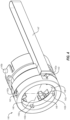
- Liquid delivery system 10 can be used to store and deliver a liquid, and output dosage information to a user.
- Liquid delivery system 10 includes cap device 100 and liquid delivery device 200.
- Liquid delivery device 200 includes a reservoir 201, delivery end 202, and a plunger 205 that can be operated to deliver a dose of the liquid within reservoir 201 through delivery end 202.
- Cap device 100 is positionable over delivery end 202 of liquid delivery device 200 for storage of liquid delivery device 200 between uses.
- Liquid delivery device 200 may be configured to deliver a measured dose of a liquid to a subject for the treatment of a medical condition.
- liquid delivery device 200 may be a pen injector for delivering a liquid, such as insulin, to manage diabetes.
- delivery end 202 of liquid delivery device 200 includes a septum 203 and an injection needle 204.
- a desired dosage may be measured by operation of dial 206 (e.g. by manually rotating dial 206), and delivered by advancing plunger 205.
- Advancement of plunger 205 via rod 214 pushes the measured dosage of liquid from reservoir 201, through delivery end 202, and into the subject.
- advancement of plunger 205 a particular distance causes a corresponding volume of liquid to be dispensed from liquid delivery device 200.
- Cap device 100 includes a body 110 that defines a cavity 111 configured to receive at least a portion of liquid delivery device 200, such as at least a portion of delivery end 202 and/or reservoir 201. Cap device 100 is positionable over delivery end 202 and may retain liquid delivery device 200 (e.g. between periods of use). Cap device 100 may protect delivery end 202 from damage or contaminants of the external environment, and contain injection needle 204. Liquid delivery device 200 may be removed from cavity 111 of cap device 100 before each use, and subsequently engaged with cap device 100 after a dose has been delivered. Cap device 100 may thus be removed from and replaced onto liquid delivery device 200 over multiple uses.
- Cap device 100 may include various components that facilitate calculation, display, storage, and/or communication of sensor signals that may be output by the one or more sensors.
- cap device 100 includes a display 121, user inputs 122, communication device 123, memory 124, processor 125, speaker 126, and circuit board 127.
- One or more components may be in electrical communication with one or more other components via circuit board 127, and processor 125 may be configured with logic to control operation of one or more of display 121, user inputs 122, communication device 123, memory 124, and speaker 126, and to process sensor signals received from one or more sensors of cap device 100.
- Display 121 provides a visual output to a user related to a condition of cap device 100 and/or liquid delivery device 200.
- Display 121 may be an LED or LCD display, for example.
- display 121 may provide a visual indication related to a volume of a dose delivered by liquid delivery device 200, a remaining total volume of liquid within reservoir 201, a remaining number of doses within reservoir 201, a remaining duration until reservoir 201 is emptied, a time of the previous dose (e.g. a time the cap device 100 was replaced on liquid delivery device 200), an elapsed time since the last dose (e.g. an elapsed time since cap device 100 was replaced on liquid delivery device 200), and/or other information related to liquid delivery device 200.
- a time of the previous dose e.g. a time the cap device 100 was replaced on liquid delivery device 200
- an elapsed time since the last dose e.g. an elapsed time since cap device 100 was replaced on liquid delivery device 200
- other information related to liquid delivery device 200
- Cap device 100 optionally includes one or more user inputs 122 that facilitate user interaction with cap device 100.
- user inputs 122 include first and second buttons that may be operated to control cap device 100.
- user inputs 122 may be operated by a user to activate cap device 100 and/or select information to be displayed by display 121.
- user inputs 122 may be operated to reset settings and/or memory 124 of cap device 100, such as when cap device 100 is engaged with a new liquid delivery device 200.
- cap device 100 does not include user inputs 122, such as buttons. Cap device 100 that does not include buttons or other user inputs may promote the perception of a fully automated cap device 100 and/or improve user operability.
- Cap device 100 may communicate with one or more other components of a liquid delivery system to deliver and/or receive information related to a condition of cap device 100 and/or liquid delivery device 200.
- cap device 100 includes a communication device 123 configured to communicate with one or more components remote from cap device 100.
- Communication device 123 may include a wireless communication printed circuit assembly configured for wireless communication, such as via short-wavelength UHF' radio frequency, RF communication, WI-FI, BLUETOOTH, ZIGBEE, etc.
- communication device 123 may include an electrical port for wired communication with another electronic device.
- communication device 123 is configured for two-way communication, such as two-way communication with a mobile device having software configured to deliver and receive communications with cap device 100.
- cap device 100 may be configured for one-way communication, such as only to upload information to the mobile device, or only to receive information from the mobile device.
- Communication device 123 may be configured to communicate with an electronic device configured with diabetes management software. For example, communication device 123 may transmit information related to liquid delivery device 200 that may be further processed by the electronic device. In this way, cap device 100 may facilitate review of information collected by its sensors by a remote user or healthcare provider, provide alerts related to liquid delivery system 200 by the electronic device (e.g. related to a scheduled time for an injection, a nearly empty liquid delivery device, etc.), and/or facilitate additional processing and analysis of the information collected by cap device 100.
- Cap device 100 includes a power source 170.
- power source 170 comprises one or more batteries, such as alkaline batteries, nickel cadmium batteries, lithium ion batteries, etc.
- Power source 170 may be associated with a micro-switch configured to switch cap device between an inactive or low power state to an active or operational state in which sensors of cap device 100 are active.
- a sensor signal from one or more sensors of cap device 100 such as one or more position sensors, may provide an alert to processor 125 to switch cap device to the active or operational state.
- body 110 of cap device 100 defines cavity 111 configured to receive at least a portion of liquid delivery device 200.
- Body 110 may be configured to house various components of cap device 100, such as display 121, user inputs 122, communication device 123, memory 124, processor 125, speaker 126, and circuit board 127.
- body 110 is a molded body, such as a molded plastic.
- Body 110 may include multiple body portions that are assembled to from body 110, such as a first body portion 110a and a second body portion 110b that may be joined to define cavity 111 and/or other spaces to accommodate components of cap device 100.
- a body 110 that includes first and second body portions 110a, 110b may facilitate efficient manufacturing of body 110 and/or efficient assembly with other components of cap device 100.
- the portion of body 110 that defines cavity 111 may be integrally formed as a unitary component (e.g. such that multiple components do not need to be joined in order to define cavity 111).
- Body 110 includes a front wall 112, side walls 113, and an opening 114 to cavity 111.
- Cavity 111 is at least partially defined by front wall 112 and side walls 113.
- Front wall 112 includes a feature configured to receive delivery end 202 and/or injection needle 204 of liquid delivery device 200, such as a receptacle 112a including plug 112b ( FIG. 2 ) that at least partially surrounds injection needle 204.
- front wall 112 may include one or more retention features that engage with liquid delivery device 200 and limit relative movement between liquid delivery device 200 and body 110 of cap device 100.
- Wiper 145b may be biased towards resistive element 145a by an elastic element 145c, such as a spring arm or spring ( FIG. 3 ) to promote continuous contact between resistive element 145a and wiper 145b.
- the elastic element 145c provides a relatively low bias such that wiper 145b remains in contact with resistive element 145a while frictional resistance or wear of resistive element 145a is reduced.
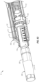
- sensor carriage 140 includes engagement features configured to interact with track 150 and/or liquid delivery device 200.
- arms 146 of sensor carriage 140 may guide sensor carriage 140 along slots 151. Arms 146 extend at least partially into slots 151 so that sensor carriage 146 is limited to movement in a path directed by slots 151, and rotation of sensor carriage 140 is prevented.
- Slots 151 may include a substantially straight portion parallel to central longitudinal axis A of cavity 111. Alternatively or additionally, slots 151 may include curved or helical portions that cause sensor carriage 140 and/or track 150 to rotate relative to one another and/or other components of cap device 140 as sensor carriage 140 travels along cavity 111.
- Sensor 142 of sensor carriage 140 may output sensor signals as sensor carriage 140 travels between the first and second positions along liquid delivery device 200.
- path 142c between emitter 142a and receiver 142b intersects delivery end 202 of liquid delivery device 200.
- the sensor signals may be evaluated (e.g. by processor 125) to detect the presence of a leading end of reservoir 201, such as a location immediately reward of tapered walls 204a.
- a magnitude of radiation received by receiver 142b may increase or step up between a location at which optical path 142c passes through tapered walls 204a and a location at which optical path 142c passes through walls 204b oriented substantially parallel to a longitudinal axis of reservoir 201.
- a particular magnitude of the sensor signal, or an increase in the magnitude of the sensor signal may thus provide an indication of the leading end of reservoir 201.
- FIG. 6C shows sensor carriage 140 in a second position in which sensor carriage 140 is located proximate opening 114 of cavity 111.
- sensor carriage 140 In the second position, sensor carriage 140 has traveled beyond leading surface 205a of plunger 205 such that path 142c intersects plunger 205.
- the presence of leading surface 205a may be detected by a change in the sensor signal at the location path 142c encounters leading surface 205a. For example, a magnitude of radiation received by receiver 142b may be reduced or stepped down due to the presence of plunger 205 in path 142c.
- Liquid delivery system 20 includes cap device 300 and liquid delivery device 400.
- Liquid delivery device 400 includes a reservoir 401, delivery end 402, and a plunger 405 that can be operated to deliver a dose of the liquid within reservoir 401 through delivery end 402.
- Cap device 300 is positionable over delivery end 402 of liquid delivery device 400 for storage of liquid delivery device 400 between uses.
- cap device 300 includes one or more sensors, including a linear encoder.
- Liquid delivery device 400 may be configured to deliver a measured dose of a liquid to a subject for the treatment of a medical condition.
- liquid delivery device 400 may be a pen injector for delivering a liquid, such as insulin, to manage diabetes.
- delivery end 402 of liquid delivery device 400 includes a septum 403 and an injection needle 404.
- a desired dosage may be measured by operation of dial 406 (e.g. by manually rotating dial 406), and operating liquid delivery device 400 to advance the plunger.
- Advancement of plunger 405 via rod 414 pushes the measured dosage of liquid from reservoir 401, through delivery end 402, and into the subject.
- advancement of plunger 405 a particular distance results in a corresponding volume of liquid dispensed from liquid delivery device 400.
- Cap device 300 may include one or more sensors configured to detect a condition of liquid delivery device 400.
- cap device 300 includes sensors that output sensor signals that may be evaluated to detect a plunger, a position of the plunger, a change in position of the plunger between successive engagements with cap device 300 (e.g. a change in position after delivery of a dose), and/or other conditions of liquid delivery device 400.
- the position of the plunger, and/or a change in the position of the plunger may be used to monitor a volume of a dose delivered by liquid delivery device 400, a remaining total volume of liquid within reservoir 402, a remaining number of doses within reservoir 402, a remaining duration until reservoir 402 is emptied, and/or other information related to liquid delivery device 400.
- Cap device 300 optionally includes user inputs 322 that facilitate user interaction with cap device 100.
- user inputs 322 include first and second buttons that may be operated to control cap device 300.
- user inputs 322 may be operated by a user to activate cap device 300 and/or select information for display by display 321.
- user inputs 322 may be operated to reset settings and/or memory of cap device 300, such as when cap device 300 is engaged with a new liquid delivery device 400.
- cap device 300 does not include manually-operable user inputs. Cap device 300 that does not include buttons or other user inputs may improve ease of operability and promote the perception of a fully automated cap device 300.
- Cap device 300 may communicate with one or more other components of a liquid delivery system to deliver and/or receive information related to a condition of cap device 100 and/or liquid delivery device 400.
- cap device 300 includes a communication device 323 configured to communicate with one or more components remote from cap device 300.
- Communication device 323 may include a wireless communication printed circuit assembly configured for wireless communication, such as via short-wavelength UHF' radio frequency, RF communication, WI-FI, BLUETOOTH, ZIGBEE, etc.
- communication device 323 may include an electrical port for wired communication with another electronic device.
- communication device 323 is configured for two-way communication, such as two-way communication with a mobile device having software configured to deliver and receive communications with cap device 300.
- cap device 300 may be configured for one-way communication, such as only to upload information to the mobile device, or only to receive information from the mobile device.
- Communication device 323 may be configured to communicate with an electronic device configured with diabetes management software. For example, communication device 323 may transmit information related to liquid delivery device 400 that may be further processed by the electronic device. In this way, cap device 300 may facilitate remote review of information collected by its sensors by a remote user or healthcare provider, provide alerts related to liquid delivery system 400 by the electronic device (e.g. related to a scheduled time for an injection, a nearly empty liquid delivery device, etc.), and/or facilitate additional processing of the information collected by cap device 300.
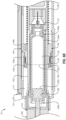
- Sensor carriage 340 includes one or more sensor components configured to detect a condition of liquid delivery device 400 as the sensor carriage moves between a first position and a second position.
- sensor carriage 340 includes components of a plunger sensor, such as an optical sensor, and a position sensor, such as linear encoder, configured to detect information that can be used to evaluate a condition of liquid delivery device 400.
- sensor carriage 340 may include only components of a position sensor (e.g. and not a plunger sensor).
- one or more optical sensors 344 may be fixedly positioned on body 310 of cap device 300.
- sensor carriage 340 has a sensor 342 (e.g. a plunger sensor) that includes an emitter 342a and a receiver 342b, such as an optical emitter 342a and optical emitter 342b.
- Optical emitter 342a emits radiation that can be detected by optical receiver 342b, and in some embodiments may include an LED or laser diode.
- Optical receiver 342b may output a signal related to the amount of radiation received from optical emitter 342a, which may be dependent on the portion of liquid delivery device 400 present in path 342c between optical emitter 342a and optical received 342b. The amount of radiation received by optical receiver may thus be relatively lower when path 342c intersects plunger or other solid structure, and may be relatively higher when path 342c intersects transparent walls of a reservoir and its liquid contents.
- sensor carriage 340 may include a position sensor 345 configured to output a sensor signal indicative of a position or distance.
- cap device 300 includes a position sensor 345 that outputs a sensor signal indicative of a position of sensor carriage 340 and/or distance sensor carriage 340 traveled between a first position and a second position (e.g. as sensor carriage 340 moves along liquid delivery device 400 or between subsequent doses of liquid delivery device 400).
- position sensor 345 includes a linear encoder, such as a reflective linear encoder or a transmissive linear encoder.
- An encoder codestrip 345a is located at least partially along a length of cavity 311, such as side wall 313 of body 310 or track 350.
- An encoder 345b such as an optical encoder, is located on sensor carriage 340. In some example embodiments, encoder 345b may be positioned in close proximity to codestrip 345a but out of contact with codestrip 345a.
- the resolution of the encoder may be enhanced to a resolution finer than the thickness of the alternating lines of codestrip 345a by detecting a transition at the leading edge of each line and/or velocity-based interpolation techniques.
- linear encoder 345 may provide a highly accurate and reliable measurement having a resolution of less than 25 ⁇ m, less than 15 ⁇ m, less than 10 ⁇ m, between about 5 ⁇ m and 10 ⁇ m, or about 7.5 ⁇ m.
- the resolution of liquid delivery device 400 may be about 130 ⁇ m.
- the resolution of sensor 345 of cap device 300 may thus be between about 10 to 20 times the resolution of liquid delivery device 400.
- Such resolutions of sensor 345 facilitates a highly accurate determination of a position of plunger 405 with a significantly smaller error than the variation in dose delivery by liquid delivery device 400.
- high resolution may be achieved with little or no calibration of sensor 345 during assembly of cap device 300.
- Encoder 345b is out of contact during operation of sensor 345 such that encoder 345b is separated from codestrip 345a by a space. Encoder 345b thus does not create frictional resistance by contact with codestrip 345a, and frictional wear does not occur. Encoder 345b can repeatedly travel along codestrip 345a without wearing or otherwise affecting codestrip 345a.
- an optional spring 348 may be included to provide controlled drag against the motion of sensor carriage 340 propelled by spring 360. Controlled movement of sensor carriage 340 may be facilitated without causing frictional engagement or wear on components of sensors 342, 344, or 345, for example.
- a sensor 344 fixedly positioned on body 310 of cap device 300 may be used to detect the plunger and/or other features of liquid delivery device 400. Sensors 344 may output sensor signals as liquid delivery device 400 is inserted into cavity 311 and brought into engagement with cap device 300.
- Spring 360 may promote controlled manual insertion of liquid delivery device 400 into cavity 311(e.g. within a bore that receives liquid delivery device 400) of cap device 300.
- Liquid delivery system 30 includes cap device 500 that is positionable over a delivery end of a liquid delivery device for storage of the liquid delivery device between uses.
- cap device 500 includes one or more sensors configured to detect a condition of the liquid delivery device, such as a position of its plunger, and one or more output devices, such as a display, communication system, etc., configured to output information related to the condition of the liquid delivery device.
- liquid delivery system 30 includes features similar to features of liquid delivery systems 10 and 20 described above with reference to FIGS. 1 through 12 .
- Cap device 500 includes one or more sensor components configured to detect a condition of the liquid delivery device as the liquid delivery device is brought into engagement with cap device 500.
- cap device 500 includes a plunger sensor and/or a rotary encoder, configured to detect information that can be used to evaluate a condition of a liquid delivery device.
- cap device 500 includes one or more sensors 544 fixedly positioned proximate opening 514 of cavity 511. Sensors 544 may include an emitter 542a and a receiver 542b, such as an optical emitter 542a and optical emitter 542b.
- Optical emitter 542a emits radiation that can be detected by optical receiver 542b, and in some embodiments may include an LED or laser diode.
- Optical receiver 542b may output a signal related to the amount of radiation received from optical emitter 542a, which may be dependent on the portion of the liquid delivery device present in path 542c between optical emitter 542a and optical receiver 542b.
- the amount of radiation received by optical receiver may thus be relatively lower when a plunger or other solid structure is present in path 542c, and may be relatively higher when transparent walls of a reservoir and its liquid contents are present in path 542c.
- cap device 500 may include components of a position sensor configured to output a sensor signal indicative of a position or distance.
- cap device 500 includes a rotary encoder 570 that outputs a sensor signal indicative of a position of carriage 540 and/or distance carriage 540 traveled between a first position and a second position (e.g. as carriage 540 is pushed along cavity 511 during engagement of cap device 500 with a liquid delivery device).
- gear train may include gears 581a, 581b, 581c, 581d, 581e, that provide a gear ratio between 2 and 100, 4 and 50, 8 and 25, or of about 16.
- Gears 581a, 581c, 581e may be rotatable on main shaft 582 supported by a bearing 583, for example, and gears 581b, 581d, rotatable on gear post 589. Accordingly, in some embodiments, each rotation of track 150 may produce multiple rotations of codewheel 545a.
- encoder 545b may be out of contact with codewheel 545a during operation of rotary encoder 545 such that encoder 545b is separated from codewheel 545a by a space. Encoder 545b thus does not create frictional resistance by contact with codewheel 545a, and frictional wear of codewheel 545a due to contact by encoder 545b does not occur. Encoder 345b can repeatedly detect codewheel 345a without wearing or otherwise affecting codewheel 345a.
- Operation 802 may include aligning the liquid delivery device with the cavity of the cap device, such as aligning a central longitudinal axis of the liquid delivery device with a central longitudinal axis of the cavity of the cap device.
- operation 802 may include aligning the liquid delivery device into one or more discrete alignment positions with the cap device.
- liquid delivery device and/or cap device may have an asymmetrical feature and/or non-circular shape that facilitates receiving the liquid delivery device in one or more discrete positions selected based on locations of one or more sensors within the cap device.
- Operation 802 including aligning the liquid delivery device with the cap device in a particular orientation facilitates desired interaction between one or more sensors of the cap device and the liquid delivery device by reducing interference or obstruction by ribs, indicia, opaque regions, and/or other features.
- operation 802 of receiving the liquid delivery device with the cavity of the cap device may include fixedly engaging the cap device with the liquid delivery device.
- relative motion between the liquid delivery device and the cap device may be limited such that the liquid delivery device is not rotatable within the cavity and/or the liquid delivery device is not movable longitudinally within the cavity.
- Method 800 may include operation 804 of releasing a sensor carriage including one or more sensors.
- the sensor carriage When the sensor carriage is released, the sensor carriage may move from a first position to the second position while the liquid delivery device remains in a fixed position within the cavity. For example, the sensor carriage may move from a first position proximate a front wall that partially defines the cavity to a second position proximate an opening of the cavity.
- One or more sensors located on the sensor carriage operate while the sensor carriage moves between the first and second positions to output sensor signals indicative of one or more features of the liquid delivery device.
- operation 804 of releasing the sensor carriage may be initiated without additional manual operation.
- the sensor carriage may be released without manual operation.
- One or more engagement features of the sensor carriage that interact with liquid delivery device may be moved or released such that the sensor carriage and liquid delivery device are not restricted to a fixed position relative to one another.
- Method 800 may further include operation 806 of evaluating an output of the one or more sensors indicative of the presence of a feature of the liquid delivery device.
- the cap device may include a processor configured to evaluate sensor signals from one or more of the sensors, such as a variation in sensor signals indicative of the plunger, and to determine a corresponding position.
- operation 806 may include storing the corresponding position and comparing the corresponding position during subsequent capping events. Evaluating the sensor signals may including evaluating a change in position to determine the volume of the previous dose delivery (e.g. by evaluating the distance traveled by plunger 205), a remaining volume within the liquid delivery device, or other characteristics of the liquid delivery device.
- method 800 may include operation 808 of displaying an output related to the position of the plunger.
- operation 808 may include displaying the previously delivered dose.
- operation 808 may include displaying dose information related to a remaining total volume of liquid within the reservoir of the liquid delivery device, a remaining number of doses within the reservoir of the liquid delivery device, a remaining duration until the reservoir of the liquid delivery device is emptied, a time of the previous dose (e.g. a time of operation 802 of receiving the liquid delivery device within the cavity), an elapsed time since the last dose (e.g. an elapsed time since operation 802 of receiving the liquid delivery device within the cavity), and/or other information related to the liquid delivery device.
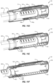
- liquid delivery system 1010 that includes a motorized cap device 1100 and liquid delivery device 1200 is shown.
- Liquid delivery system 1010 can be used to store and deliver a liquid, and output dosage information to a user, and in some example embodiments, liquid delivery system 1010 includes one or more features similar to features of liquid delivery systems 10, 20, and 30 described above with reference to FIGS. 1 through 14 .
- Liquid delivery device 1200 includes a reservoir 1201, delivery end 1202, and a plunger 1205 that can be operated to deliver a dose of the liquid within reservoir 1201 through delivery end 1202.
- Cap device 1100 is positionable over delivery end 1202 of liquid delivery device 1200 for storage of liquid delivery device 1200 between uses.
- cap device 1100 includes one or more sensors configured to detect a condition of liquid delivery device 1200, such as a position of its plunger, and one or more output devices, such as a display, communication system, etc., configured to output information related to the condition of liquid delivery device 1200.
- Liquid delivery device 1200 may be configured to deliver a measured dose of a liquid to a subject for the treatment of a medical condition.
- liquid delivery device 1200 may be a pen injector for delivering a liquid, such as insulin, to manage diabetes.
- delivery end 1202 of liquid delivery device 1200 includes a septum 1203 and an injection needle 1204.
- a desired dosage may be measured by operation of dial 1206 (e.g. by manually rotating dial 1206), and delivered by advancing plunger 1205.
- Advancement of plunger 1205 via rod 1214 pushes the measured dosage of liquid from reservoir 1201, through delivery end 1202, and into the subject.
- advancement of plunger 1205 a particular distance causes a corresponding volume of liquid to be dispensed from liquid delivery device 1200.
- Cap device 1100 includes a body 1110 that defines a cavity 1111 configured to receive at least a portion of liquid delivery device 1200, such as at least a portion of delivery end 1202 and/or reservoir 1201. Cap device 1100 is positionable over delivery end 1202 and may retain liquid delivery device 1200 (e.g. between periods of use). Cap device 1100 may protect delivery end 1202 from damage or contaminants of the external environment, and contain injection needle 1204. Liquid delivery device 1200 may be removed from cavity 1111 of cap device 1100 before each use, and subsequently engaged with cap device 1100 after a dose has been delivered. Cap device 1100 may thus be removed from and replaced onto liquid delivery device 1200 over multiple uses.
- liquid delivery device 1200 After the contents of a particular liquid delivery device 1200 has been exhausted, the liquid delivery device 1200 may be discarded, and cap device 1100 used with a new liquid delivery device.
- liquid delivery device 1200 is disposable when its usable contents are exhausted, and cap device 1100 may be reusable with multiple liquid delivery devices 1200.
- cap device 1100 may be associated with a particular liquid delivery device 1200, and both the cap device 1100 and the liquid delivery device 1200 may be disposed when the contents of reservoir 1201 are exhausted.
- Cap device 1100 may include one or more sensors configured to detect a condition of liquid delivery device 1200.
- cap device 1100 includes sensors that output sensor signals that may be evaluated to detect plunger 1205, a position of plunger 1205, a change in position of plunger 1205 between successive engagements with cap device 1100 (e.g. a change in position after delivery of a dose), and/or other conditions of liquid delivery device 1200.
- the position of plunger 1205, and/or the change in the position of plunger 1205 may be used to monitor a volume of a dose delivered by liquid delivery device 1200, a remaining total volume of liquid within reservoir 1201, a remaining number of doses within reservoir 1201, a remaining duration until reservoir 1201 is emptied, and/or other information related to liquid delivery device 1200.
- Cap device 1100 may include various components that facilitate calculation, display, storage, and/or communication of sensor signals that may be output by the one or more sensors.
- cap device 1100 includes a display 1121, user inputs 1122, communication device 1123, memory 1124, processor 1125, speaker 1126, and circuit board 1127.
- One or more components may be in electrical communication with one or more other components via circuit board 1127, and processor 1125 may be configured with logic to control operation of one or more of display 1121, user inputs 1122, communication device 1123, memory 1124, and speaker 1126, and to process sensor signals received from one or more sensors of cap device 1100.
- Display 1121 provides a visual output to a user related to a condition of cap device 1100 and/or liquid delivery device 1200.
- Display 1121 may be an LED, LCD, electronic ink, or e-paper display, for example.
- display 1121 may provide a visual indication related to a volume of a dose delivered by liquid delivery device 1200, a remaining total volume of liquid within reservoir 1201, a remaining number of doses within reservoir 1201, a remaining duration until reservoir 1201 is emptied, a time of the previous dose (e.g. a time the cap device 1100 was replaced on liquid delivery device 1200), an elapsed time since the last dose (e.g. an elapsed time since cap device 1100 was replaced on liquid delivery device 1200), and/or other information related to liquid delivery device 1200.
- a time of the previous dose e.g. a time the cap device 1100 was replaced on liquid delivery device 1200
- an elapsed time since the last dose e.g. an elapsed time since cap device 1
- cap device 1100 may include audio and/or vibratory alerts related to a condition of cap device 1100 and/or liquid delivery device 1200.
- Processor 1125 may control audio output of speaker 1126 to output an audible alert, or vibrator 1128 to output a vibratory alert, which may be perceived as an indication of a volume of a dose delivered by liquid delivery device 1200, a remaining total volume of liquid within reservoir 1201, a remaining number of doses within reservoir 1201, a remaining duration until reservoir 1201 is emptied, a time of the previous dose (e.g. a time the cap device 1100 was replaced onto liquid delivery device 1200), an elapsed time since the last dose (e.g.
- vibrator 1128 may deliver vibrations to liquid delivery device 1200. Vibrator 1128 may be activated to facilitate mixing of the contents of liquid delivery device 1200 and/or to reduce the formation or buildup of precipitates (e.g. on the leading surface of plunger and/or surfaces of reservoir 1201).
- Cap device 1100 optionally includes one or more user inputs 1122 that facilitate user interaction with cap device 1100.
- user inputs 1122 include first and second buttons that may be operated to control cap device 1100.
- user inputs 1122 may be operated by a user to activate cap device 1100 and/or select information to be displayed by display 1121.
- user inputs 1122 may be operated to reset settings and/or memory 1124 of cap device 1100, such as when cap device 1100 is engaged with a new liquid delivery device 1200.
- cap device 1100 does not include user inputs 1122, such as buttons. Cap device 1100 that does not include buttons or other user inputs may promote the perception of a fully automated cap device 1100 and/or improve user operability.
- Cap device 1100 may communicate with one or more other components of a liquid delivery system to deliver and/or receive information related to a condition of cap device 1100 and/or liquid delivery device 1200.
- cap device 1100 includes a communication device 1123 configured to communicate with one or more components remote from cap device 1100.
- Communication device 1123 may include a wireless communication printed circuit assembly configured for wireless communication, such as via short-wavelength UHF radio frequency, RF communication, WI-FI, BLUETOOTH, ZIGBEE, etc.
- communication device 1123 may include an electrical port for wired communication with another electronic device.
- communication device 1123 is configured for two-way communication, such as two-way communication with a mobile device having software configured to deliver and receive communications with cap device 1100.
- cap device 1100 may be configured for one-way communication, such as only to upload information to the mobile device, or only to receive information from the mobile device.
- Communication device 1123 may be configured to communicate with an electronic device configured with diabetes management software. For example, communication device 1123 may transmit information related to liquid delivery device 1200 that may be further processed by the electronic device. In this way, cap device 1100 may facilitate review of information collected by its sensors by a remote user or healthcare provider, provide alerts related to liquid delivery system 1010 by the electronic device (e.g. related to a scheduled time for an injection, a nearly empty liquid delivery device, etc.), and/or facilitate additional processing and analysis of the information collected by cap device 1100.
- Cap device 1100 includes a power source 1170.
- power source 1170 comprises one or more batteries, such as alkaline batteries, nickel cadmium batteries, lithium ion batteries, lithium polymer batteries, etc.
- power source 1170 may include a rechargeable 3.7 V lithium polymer battery to power a motor of a motorized drive mechanism, communication device 1123, and/or one or more other components of cap device 1100.
- Such power sources 1170 may provide an extended period of time before recharging, such as longer than five days of normal use, longer than 7 days of normal use, or longer.
- Power source 1170 may be associated with a micro-switch configured to switch cap device between an inactive or low power state to an active or operational state in which sensors of cap device 1100 are active.
- a sensor signal from one or more sensors of cap device 1100 such as one or more position sensors, may provide an alert to processor 1125 to switch cap device to the active or operational state.
- body 1110 of cap device 1100 defines cavity 1111 configured to receive at least a portion of liquid delivery device 1200 (e.g. within a bore of cavity 1111).
- body 1110 may include a front wall 1112, side walls 1113, and an opening 1114.
- Body 1110 may be configured to house various components of cap device 1100, such as display 1121, user inputs 1122, communication device 1123, memory 1124, processor 1125, speaker 1126, and circuit board 1127.
- body 1110 is a molded body, such as a molded plastic.
- Body 1110 may include multiple body portions that are assembled to form body 1110, such as a first body portion 11 10a and a second body portion 11 10b that may be joined to define cavity 1111 and/or other spaces to accommodate components of cap device 1100.
- a body 1110 that includes first and second body portions 1110a, 1110b may facilitate efficient manufacturing of body 1110 and/or efficient assembly with other components of cap device 1100.
- the portion of body 1110 that defines cavity 1111 may be integrally formed as a unitary component (e.g. such that multiple components do not need to be joined in order to define cavity 1111).
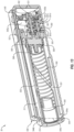
- cap device 1100 includes a sleeve 1118 (e.g. body 1110 includes a sleeve 1118) configured to receive at least a portion of liquid delivery device 1200.
- Sleeve 1118 may includes side walls 1118a and a front wall 1118b configured to receive delivery end 1202 and/or injection needle 1204 of liquid delivery device 1200.
- the sleeve at least at least partially surrounds injection needle 1204 (e.g. proximate a front of cap device 1100) and reservoir 1201 between injection needle 1204 and opening 1114.
- sleeve 1118 may include one or more retention features that engage with liquid delivery device 1200 and limit relative movement between liquid delivery device 1200 and body 1110 of cap device 1100.
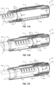
- Motorized cap device 1100 includes sensor carriage 1140 that is movable within body 1110 (e.g. movable within cavity 1111 between walls 1113 and sleeve 118). Sensor carriage 1140 is configured to travel along at least a portion of liquid delivery device 200 within cavity 111, and cavity 1111 is sized to accommodate the dimensions of liquid delivery device 1200 and a path for sensor carriage 1140. Sensor carriage 1140 facilitates detection of characteristics of liquid delivery device 1200 by carrying one or more sensors along liquid delivery device. In an example embodiment, sensor carriage 1140 is movable between the first position and the second position relative to cavity 1111 while liquid delivery device 1200 remains in a fixed position relative to sleeve 1118/cavity 1111 (e.g. sensor carriage 1140 is movable while the liquid delivery device 1200 is fixedly engaged with cap device 1100).
- sensor carriage 1140 is located entirely outside of sleeve 1118 (e.g. such that no part of sensor carriage 1140 extends into sleeve 1118). Sleeve 1118 may thus protect sensor carriage 1140 from the external environment and/or the contents of liquid delivery device 1200.
- sleeve 1118 includes one more features configured to interact with features of liquid delivery device 1200.
- interior surfaces 1118c of sleeve 1118 may include features that orient and/or retain liquid delivery device 1200 within cap device 1100.
- Sleeve 1118 may at least partially surround reservoir 1201 of liquid delivery device 1200, and sensor carriage 1140 may be movable between sleeve 1118 and side walls 1113 that define cavity 1111 of cap device 1100.
- sleeve 1118 is positioned between liquid delivery device 1200 and sensor carriage 1140 during operation of sensor carriage 140.
- Sleeve 1118 may be at least partially constructed from an optically clear material, for example, or other material that allows operation of the sensors associated with sensor carriage 1140.
- sleeve 1118 may be integrally formed with body 1110 of cap device 1100.
- sleeve 1118 may be integrally formed with body 1110 as a unitary component.
- sleeve 1118 may be formed as a component separate from other components of body 1110 and subsequently assembled with the other components of body 1110.
- sleeve 1118 may be sealing joined to other components of body 1110 proximate opening 1114 and/or other locations of body 1110.
- a separately formed sleeve 1118 may facilitate manufacture of sleeve 1118 (e.g. which may optionally have tighter manufacturing tolerances and/or include features otherwise difficult to form within cavity 1111 of body 1110).
- Sleeve 1118 may protect electronic and other components within body 1110 from liquid, debris, and environmental contaminants.
- sleeve 1118 is sealed with other components of body 1110 and/or does not define openings into cavity 1111. Cavity 1111 may thus define a hermetically sealed cavity.
- Sensor carriage 1140 driven by motorized drive system 1160 e.g. exclusively driven by motorized drive system 1160
- Such a construction may provide a robust liquid delivery system 1010 in which mechanical and electronic components are protected.
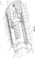
- Cap device 1100 includes a motorized drive system 1160 configured to drive sensor carriage 1140 along a longitudinal axis of cap device 100 (e.g. along a longitudinal axis extending centrally through front wall 112 and opening 114).
- motorized drive system 1160 may include a motor 1161 and leadscrew 1162 connected, directly or indirectly, to a drive shaft of motor 1161. Rotation of the leadscrew 1162 caused be operation of motor 1161 results in movement of sensor carriage. Rotation of motor 1161 in a first direction results in movement of sensor carriage 1140 towards opening 1114 of cavity 1111 and rotation of motor 1161 in a second direction results in movement of sensor carriage 1140 towards front wall 1112 of body 1110.
- motorized drive system 1160 can thus drive sensor carriage 1140 between any number of discrete points along leadscrew 1162.
- liquid delivery device 1200 remains in a fixed position relative to cavity 1111 and body 1110 of cap device 1100 while sensor carriage 1140 travels along liquid delivery device 1200.
- Liquid delivery device 1200 is constrained against twisting or rotation about longitudinal axis A of cavity 1111, and/or may be constrained from longitudinal movement along longitudinal axis A. Limited or no relative movement between liquid delivery device 1200 and body 1110 facilitates accurate and repeatable detection of plunger 1205 by sensors of sensor carriage 1140, and provides a predictable line of sight for the sensors of sensor carriage 1140.
- emitter 1142a is configured to generate a narrow beam with limited spread outside of optical path 1142c, such as by an emitter 1142a that emits a narrow beam and/or by a collimating structure configured to focus the output of emitter 1142a along path 1142c.
- radiation emitted by emitter 1142a may be within visible and/or invisible wavelengths.
- Sensor carriage 1140 may include multiple sensors, such as first and second optical sensors 1142, 1143, each including an emitter and a receiver, for example.
- first and second optical sensors 1142, 1143 each including an emitter and a receiver, for example.
- the relative locations of first and second sensors may be selected to promote an appropriate line of sight (e.g. through liquid delivery device 1200) by at least one of the first and second sensors.
- sensor carriage 1140 may be driven by motorized drive system 1160 to a position in which sensor carriage 1140 is in electrical communication with circuit board 1127 and/or processor 1125 such that the collected information may be communicated.
- the sensor carriage 1140 begins at an initial position near front wall 1112 of body 1110 after a new liquid delivery device 1200 is engaged with cap device 1100.
- sensor carriage 1140 is driven by motorized drive system 1160 in a first direction towards opening 1114 until plunger 1205 of liquid delivery device 1200 is encountered. Operation of motorized drive system 1160, and movement of sensor carriage 1140, is then stopped and the sensor carriage 1140 remains at the location where plunger 1205 was detected.
- sensor carriage 1140 is driven by motorized drive system 1160 in the first direction towards opening 1114 until plunger 1205 of liquid delivery device 1200 is encountered, and operation of motorized drive system 1160 and movement of sensor carriage 1140 is again stopped. Intermittent operation of motorized drive system 1160, and corresponding movement of sensor carriage 1140, is repeated until the liquid delivery device 1200 is exhausted or a new liquid delivery device engaged with cap device 1100.
- sensor carriage 1140 may repeatedly initiate movement from a common starting point each time liquid delivery device 1200 is engaged with cap device 1100. For example, sensor carriage 1140 may begin movement from a position near delivery end 1202 of liquid delivery device 1200 and move in a first direction towards opening 1114. After a dosing event, motorized drive system 1160 may return sensor carriage in a second direction towards front wall 1112 back to the initial position. This process may continue for a series of dosing events. The travel distance of each successive operation from the first or initial position to the second position (e.g. where plunger 1205 is detected) may become successively shorter as plunger 1205 is advanced within liquid delivery device 1200 during each dosing event.
- Motorized drive system 1160 may be configured to vary the speed of sensor carriage 1140. In some embodiments, the speed of sensor carriage 1140 may be varied depending on whether sensor carriage 1140 is operating to detect a characteristic of liquid delivery device 1200. Motorized drive system 1160 may drive sensor carriage 1140 at a first speed during operation of sensor 1142 to detect a characteristic of liquid delivery device 1200, and may drive sensor carriage 1140 at a second speed (e.g. higher than the first speed) when driving sensor carriage 1140 to a position while sensor 1142 is not operating to detect a characteristic of liquid delivery device 1200.
- a second speed e.g. higher than the first speed
- motorized drive system 1160 may continuously vary the speed of sensor carriage 1140, such as by continuously decreasing the speed between an initial location (e.g. where plunger 1205 is unlikely to be present) and a second location (e.g. where plunger 1205 is located). Such adjustment of the speed of sensor carriage 1140 may promote a selected scan resolution, reliability, and/or precision in detecting the position of plunger 1205, for example, while reducing the scan duration, power consumption noise generation, etc.
- Motorized drive system 1160 may be configured to facilitate improved reliability and repeatability in detecting plunger 1205 or another characteristic of liquid delivery system 1000.
- motorized drive system 1160 facilitates multiple measurements at a single position or series of positions while liquid delivery device 1200 remains fixedly engaged with cap device 1100.
- motorized drive system 1160 may drive sensor carriage 1140 in one or more back and forth movements proximate a location of interest to obtain multiple measurements. The measurements may then be averaged or otherwise processed (e.g. by processor 1125) to provide a reliable and repeatable output.
- Motorized drive system 1160 may be activated by engagement between cap device 1100 and liquid delivery device 100.
- cap device 1100 may include a sensor 1180 located to detect the present of liquid delivery device 1200 within sleeve 1118.
- Sensor 1180 may be a contact switch, optical sensor, etc.
- sensor 1180 may emit a signal indicative of the presence of liquid delivery device 1200.
- Motorized drive system 1160 may be activated to drive sensor carriage 140 after sensor 1180 emits a signal indicating that liquid delivery device 1200 has been engaged with cap device 1100.
- motorized drive system 1160 may be activated to drive sensor carriage 140 by the signal emitted by sensor 1180.
- motorized drive system 1160 may be activated to drive sensor carriage 1140 a predetermined time (e.g. 1 second, 2 seconds, 5 seconds, etc.) after sensor 1180 emits a signal indicating the presence of liquid delivery device 1200.
- a predetermined period may ensure that liquid delivery device 1200 is fully engaged and in a fixed position relative to cap device 1100, and/or that the contents of reservoir 1204 have settled, before driving sensor carriage 1140 to detect plunger 1205 or other feature of liquid delivery system 1010.
- Method 1800 includes operation 1802 of receiving at least a portion of a liquid delivery device within a cavity of a cap device.
- the liquid delivery device may have features and characteristics similar to liquid delivery devices 200, 400, 600, 1200 described herein, and may be a pen-injector device for administering a dose of insulin.
- Operation 1802 may include aligning the liquid delivery device with the cavity of the cap device, such as aligning a central longitudinal axis of the liquid delivery device with a central longitudinal axis of the cavity of the cap device.
- operation 1802 may include aligning the liquid delivery device into one or more discrete alignment positions with the cap device.
- liquid delivery device and/or cap device may have an asymmetrical feature and/or non-circular shape that facilitates receiving the liquid delivery device in one or more discrete positions selected based on locations of one or more sensors within the cap device.
- Operation 1802 including aligning the liquid delivery device with the cap device in a particular orientation facilitates desired interaction between one or more sensors of the cap device and the liquid delivery device by reducing interference or obstruction by ribs, indicia, opaque regions, and/or other features.
- operation 1802 of receiving the liquid delivery device with the cavity of the cap device may include fixedly engaging the cap device with the liquid delivery device.
- relative motion between the liquid delivery device and the cap device may be limited such that the liquid delivery device is not rotatable within the cavity and/or the liquid delivery device is not movable longitudinally within the cavity.
- operation 1804 of driving the sensor carriage may be initiated without additional manual operation.
- the cap device may detect engagement with the liquid delivery device, such as by a sensor, and initiate operation of the motorized drive system after detecting liquid delivery device.
- Operation 1804 may optionally include driving the sensor carriage in multiple directions.
- the motorized drive system may drive the sensor carriage in one or more back and forth movements, such as to obtain multiple measurements over a particular location or locations.
- the sensor carriage may be driven by the motorized drive system, including in back and forth directions, while the liquid delivery device remains fixedly positioned relative to the cap device, and/or without additional manual intervention, for example.
Landscapes
- Health & Medical Sciences (AREA)
- Vascular Medicine (AREA)
- Engineering & Computer Science (AREA)
- Anesthesiology (AREA)
- Biomedical Technology (AREA)
- Heart & Thoracic Surgery (AREA)
- Hematology (AREA)
- Life Sciences & Earth Sciences (AREA)
- Animal Behavior & Ethology (AREA)
- General Health & Medical Sciences (AREA)
- Public Health (AREA)
- Veterinary Medicine (AREA)
- Infusion, Injection, And Reservoir Apparatuses (AREA)
- Loading And Unloading Of Fuel Tanks Or Ships (AREA)
- Reciprocating Pumps (AREA)
Applications Claiming Priority (3)
| Application Number | Priority Date | Filing Date | Title |
|---|---|---|---|
| US201862648046P | 2018-03-26 | 2018-03-26 | |
| EP18840069.1A EP3773817B1 (de) | 2018-03-26 | 2018-12-18 | Flüssigkeitsabgabekappen-vorrichtungen, -systeme und -verfahren |
| PCT/IB2018/060267 WO2019186261A1 (en) | 2018-03-26 | 2018-12-18 | Cap devices, systems, and methods for liquid delivery devices |
Related Parent Applications (1)
| Application Number | Title | Priority Date | Filing Date |
|---|---|---|---|
| EP18840069.1A Division EP3773817B1 (de) | 2018-03-26 | 2018-12-18 | Flüssigkeitsabgabekappen-vorrichtungen, -systeme und -verfahren |
Publications (2)
| Publication Number | Publication Date |
|---|---|
| EP4397340A2 true EP4397340A2 (de) | 2024-07-10 |
| EP4397340A3 EP4397340A3 (de) | 2024-09-18 |
Family
ID=65237095
Family Applications (2)
| Application Number | Title | Priority Date | Filing Date |
|---|---|---|---|
| EP24162212.5A Pending EP4397340A3 (de) | 2018-03-26 | 2018-12-18 | Kappenvorrichtungen, systeme und verfahren für flüssigkeitsabgabevorrichtungen |
| EP18840069.1A Active EP3773817B1 (de) | 2018-03-26 | 2018-12-18 | Flüssigkeitsabgabekappen-vorrichtungen, -systeme und -verfahren |
Family Applications After (1)
| Application Number | Title | Priority Date | Filing Date |
|---|---|---|---|
| EP18840069.1A Active EP3773817B1 (de) | 2018-03-26 | 2018-12-18 | Flüssigkeitsabgabekappen-vorrichtungen, -systeme und -verfahren |
Country Status (7)
| Country | Link |
|---|---|
| US (2) | US11819667B2 (de) |
| EP (2) | EP4397340A3 (de) |
| JP (3) | JP7344899B2 (de) |
| AU (2) | AU2018416009B2 (de) |
| CA (1) | CA3094761A1 (de) |
| IL (1) | IL277627B2 (de) |
| WO (1) | WO2019186261A1 (de) |
Families Citing this family (2)
| Publication number | Priority date | Publication date | Assignee | Title |
|---|---|---|---|---|
| WO2023028268A1 (en) * | 2021-08-26 | 2023-03-02 | Credence Medsystems, Inc. | System and method for collecting injection information |
| WO2025119642A1 (en) * | 2023-12-04 | 2025-06-12 | Shl Medical Ag | Medicament delivery device and method for operating a medicament delivery device |
Family Cites Families (18)
| Publication number | Priority date | Publication date | Assignee | Title |
|---|---|---|---|---|
| EP2286857A1 (de) | 2002-07-02 | 2011-02-23 | Panasonic Corporation | Automatische Verabreichungsvorrichtung für medizinische Anwendungen |
| DE10330985A1 (de) * | 2003-07-09 | 2005-02-17 | Tecpharma Licensing Ag | Vorrichtung zur Verabreichung eines fluiden Produkts mit optischer Abtastung |
| EP2182456B1 (de) * | 2008-10-28 | 2018-11-28 | Roche Diabetes Care GmbH | Vorrichtung zur Überwachung des Betriebs einer Arzneimittelabgabevorrichtung, elektronisches Modul und Arzneimittelabgabesystem |
| CN104888316B (zh) * | 2009-02-27 | 2017-08-08 | 生命扫描有限公司 | 给药系统 |
| NL2005017C2 (en) | 2010-07-01 | 2012-01-03 | Techlund Ab | Replaceable cap for a dosing device. |
| CN103957961B (zh) | 2011-10-07 | 2016-08-17 | 诺沃—诺迪斯克有限公司 | 用于基于三轴磁性传感器确定元件位置的系统 |
| EP3295979B1 (de) | 2012-02-13 | 2020-06-03 | Sanofi-Aventis Deutschland GmbH | Überwachungsvorrichtung zur überwachung des betriebs einer arzneimittelabgabevorrichtung |
| US8817258B2 (en) * | 2012-05-21 | 2014-08-26 | Common Sensing Inc. | Dose measurement system and method |
| WO2014020008A1 (en) | 2012-08-03 | 2014-02-06 | Sanofi-Aventis Deutschland Gmbh | Pen-type drug injection device and electronic add-on monitoring module for monitoring and logging dose setting and administration |
| GB2508588A (en) * | 2012-11-30 | 2014-06-11 | Owen Mumford Ltd | Medical delivery device comprising mechanical-electrical transducer |
| US9561332B2 (en) | 2013-01-15 | 2017-02-07 | Sanofi-Aventis Deutschland Gmbh | Decoding system |
| EP2981313B1 (de) | 2013-04-05 | 2017-06-14 | Novo Nordisk A/S | Arzneimittelabgabevorrichtung und protokollierungsmodulanordnung |
| JP2017531454A (ja) | 2014-08-01 | 2017-10-26 | コモン センシング インコーポレイテッド | 温度検知により最適化された液体測定システム、装置、及び方法 |
| EP3185933B1 (de) | 2014-08-28 | 2020-08-19 | UNL Holdings LLC | Sensorsysteme für wirkstofffreisetzungsvorrichtungen |
| EP4316552A3 (de) * | 2015-06-09 | 2024-04-17 | Sanofi-Aventis Deutschland GmbH | Datensammelvorrichtung zur befestigung an einer injektionsvorrichtung |
| ES2969939T3 (es) * | 2015-07-12 | 2024-05-23 | Patients Pending Ltd | Tapa para sistema de suministro de líquido con detección de posición de émbolo integrada y método correspondiente |
| DK3352818T3 (da) * | 2015-09-23 | 2020-03-16 | Sanofi Aventis Deutschland | Anordning til fastgørelse til en injektionsanordning |
| EP3175876A1 (de) | 2015-12-01 | 2017-06-07 | Carebay Europe Ltd. | Medikamentenabgabevorrichtung mit benutzerfeedbackfähigkeit |
-
2018
- 2018-12-18 US US17/041,616 patent/US11819667B2/en active Active
- 2018-12-18 EP EP24162212.5A patent/EP4397340A3/de active Pending
- 2018-12-18 WO PCT/IB2018/060267 patent/WO2019186261A1/en not_active Ceased
- 2018-12-18 AU AU2018416009A patent/AU2018416009B2/en active Active
- 2018-12-18 EP EP18840069.1A patent/EP3773817B1/de active Active
- 2018-12-18 CA CA3094761A patent/CA3094761A1/en active Pending
- 2018-12-18 IL IL277627A patent/IL277627B2/en unknown
- 2018-12-18 JP JP2020551834A patent/JP7344899B2/ja active Active
-
2023
- 2023-09-04 JP JP2023142854A patent/JP7615255B2/ja active Active
- 2023-09-28 US US18/477,205 patent/US20240181166A1/en active Pending
-
2024
- 2024-11-29 AU AU2024267065A patent/AU2024267065A1/en active Pending
- 2024-12-27 JP JP2024231672A patent/JP7829670B2/ja active Active
Also Published As
| Publication number | Publication date |
|---|---|
| US20240181166A1 (en) | 2024-06-06 |
| JP7344899B2 (ja) | 2023-09-14 |
| JP2025041948A (ja) | 2025-03-26 |
| JP2023164929A (ja) | 2023-11-14 |
| IL277627B1 (en) | 2024-04-01 |
| IL277627B2 (en) | 2024-08-01 |
| WO2019186261A1 (en) | 2019-10-03 |
| EP4397340A3 (de) | 2024-09-18 |
| US20210023306A1 (en) | 2021-01-28 |
| AU2024267065A1 (en) | 2024-12-19 |
| AU2018416009A1 (en) | 2020-10-15 |
| JP7615255B2 (ja) | 2025-01-16 |
| CA3094761A1 (en) | 2019-10-03 |
| JP7829670B2 (ja) | 2026-03-13 |
| EP3773817B1 (de) | 2024-03-20 |
| US11819667B2 (en) | 2023-11-21 |
| IL277627A (en) | 2020-11-30 |
| AU2018416009B2 (en) | 2024-09-05 |
| JP2021519139A (ja) | 2021-08-10 |
| EP3773817A1 (de) | 2021-02-17 |
Similar Documents
| Publication | Publication Date | Title |
|---|---|---|
| JP7829670B2 (ja) | 液体送達キャップ装置、システム、および方法 | |
| US8556866B2 (en) | Drug delivery system | |
| US20260054014A1 (en) | Liquid delivery cap devices, systems, and methods | |
| CN109939301B (zh) | 液体输送系统的盖装置和用于评估液体输送装置状况的方法 | |
| US20240050661A1 (en) | Liquid delivery cap devices, systems, and methods | |
| AU2020298273B2 (en) | Liquid delivery cap with alignment verification | |
| HK40071691A (en) | Liquid delivery cap with alignment verification | |
| HK1164671A (en) | Drug delivery management systems and methods |
Legal Events
| Date | Code | Title | Description |
|---|---|---|---|
| PUAI | Public reference made under article 153(3) epc to a published international application that has entered the european phase |
Free format text: ORIGINAL CODE: 0009012 |
|
| STAA | Information on the status of an ep patent application or granted ep patent |
Free format text: STATUS: REQUEST FOR EXAMINATION WAS MADE |
|
| 17P | Request for examination filed |
Effective date: 20240308 |
|
| AC | Divisional application: reference to earlier application |
Ref document number: 3773817 Country of ref document: EP Kind code of ref document: P |
|
| AK | Designated contracting states |
Kind code of ref document: A2 Designated state(s): AL AT BE BG CH CY CZ DE DK EE ES FI FR GB GR HR HU IE IS IT LI LT LU LV MC MK MT NL NO PL PT RO RS SE SI SK SM TR |
|
| REG | Reference to a national code |
Ref country code: DE Ref legal event code: R079 Free format text: PREVIOUS MAIN CLASS: A61M0005310000 Ipc: A61M0005315000 |
|
| PUAL | Search report despatched |
Free format text: ORIGINAL CODE: 0009013 |
|
| AK | Designated contracting states |
Kind code of ref document: A3 Designated state(s): AL AT BE BG CH CY CZ DE DK EE ES FI FR GB GR HR HU IE IS IT LI LT LU LV MC MK MT NL NO PL PT RO RS SE SI SK SM TR |
|
| RIC1 | Information provided on ipc code assigned before grant |
Ipc: A61M 5/31 20060101ALN20240814BHEP Ipc: A61M 5/315 20060101AFI20240814BHEP |
|
| GRAP | Despatch of communication of intention to grant a patent |
Free format text: ORIGINAL CODE: EPIDOSNIGR1 |
|
| STAA | Information on the status of an ep patent application or granted ep patent |
Free format text: STATUS: GRANT OF PATENT IS INTENDED |
|
| RIC1 | Information provided on ipc code assigned before grant |
Ipc: A61M 5/315 20060101AFI20260317BHEP Ipc: A61M 5/31 20060101ALN20260317BHEP |
|
| INTG | Intention to grant announced |
Effective date: 20260331 |
|
| RIC1 | Information provided on ipc code assigned before grant |
Ipc: A61M 5/315 20060101AFI20260323BHEP Ipc: A61M 5/31 20060101ALN20260323BHEP |