EP4397403A2 - Mélangeurs magnétiques - Google Patents
Mélangeurs magnétiques Download PDFInfo
- Publication number
- EP4397403A2 EP4397403A2 EP24156493.9A EP24156493A EP4397403A2 EP 4397403 A2 EP4397403 A2 EP 4397403A2 EP 24156493 A EP24156493 A EP 24156493A EP 4397403 A2 EP4397403 A2 EP 4397403A2
- Authority
- EP
- European Patent Office
- Prior art keywords
- impeller
- drive
- magnetic
- magnets
- torque
- Prior art date
- Legal status (The legal status is an assumption and is not a legal conclusion. Google has not performed a legal analysis and makes no representation as to the accuracy of the status listed.)
- Pending
Links
Images








Classifications
-
- B—PERFORMING OPERATIONS; TRANSPORTING
- B01—PHYSICAL OR CHEMICAL PROCESSES OR APPARATUS IN GENERAL
- B01F—MIXING, e.g. DISSOLVING, EMULSIFYING OR DISPERSING
- B01F33/00—Other mixers; Mixing plants; Combinations of mixers
- B01F33/45—Magnetic mixers; Mixers with magnetically driven stirrers
- B01F33/453—Magnetic mixers; Mixers with magnetically driven stirrers using supported or suspended stirring elements
-
- B—PERFORMING OPERATIONS; TRANSPORTING
- B01—PHYSICAL OR CHEMICAL PROCESSES OR APPARATUS IN GENERAL
- B01F—MIXING, e.g. DISSOLVING, EMULSIFYING OR DISPERSING
- B01F33/00—Other mixers; Mixing plants; Combinations of mixers
- B01F33/45—Magnetic mixers; Mixers with magnetically driven stirrers
-
- B—PERFORMING OPERATIONS; TRANSPORTING
- B01—PHYSICAL OR CHEMICAL PROCESSES OR APPARATUS IN GENERAL
- B01F—MIXING, e.g. DISSOLVING, EMULSIFYING OR DISPERSING
- B01F35/00—Accessories for mixers; Auxiliary operations or auxiliary devices; Parts or details of general application
- B01F35/20—Measuring; Control or regulation
- B01F35/21—Measuring
- B01F35/212—Measuring of the driving system data, e.g. torque, speed or power data
-
- B—PERFORMING OPERATIONS; TRANSPORTING
- B01—PHYSICAL OR CHEMICAL PROCESSES OR APPARATUS IN GENERAL
- B01F—MIXING, e.g. DISSOLVING, EMULSIFYING OR DISPERSING
- B01F35/00—Accessories for mixers; Auxiliary operations or auxiliary devices; Parts or details of general application
- B01F35/20—Measuring; Control or regulation
- B01F35/21—Measuring
- B01F35/2132—Concentration, pH, pOH, p(ION) or oxygen-demand
-
- B—PERFORMING OPERATIONS; TRANSPORTING
- B01—PHYSICAL OR CHEMICAL PROCESSES OR APPARATUS IN GENERAL
- B01F—MIXING, e.g. DISSOLVING, EMULSIFYING OR DISPERSING
- B01F35/00—Accessories for mixers; Auxiliary operations or auxiliary devices; Parts or details of general application
- B01F35/20—Measuring; Control or regulation
- B01F35/21—Measuring
- B01F35/2134—Density or solids or particle number
-
- B—PERFORMING OPERATIONS; TRANSPORTING
- B01—PHYSICAL OR CHEMICAL PROCESSES OR APPARATUS IN GENERAL
- B01F—MIXING, e.g. DISSOLVING, EMULSIFYING OR DISPERSING
- B01F35/00—Accessories for mixers; Auxiliary operations or auxiliary devices; Parts or details of general application
- B01F35/20—Measuring; Control or regulation
- B01F35/21—Measuring
- B01F35/2136—Viscosity
-
- B—PERFORMING OPERATIONS; TRANSPORTING
- B01—PHYSICAL OR CHEMICAL PROCESSES OR APPARATUS IN GENERAL
- B01F—MIXING, e.g. DISSOLVING, EMULSIFYING OR DISPERSING
- B01F35/00—Accessories for mixers; Auxiliary operations or auxiliary devices; Parts or details of general application
- B01F35/20—Measuring; Control or regulation
- B01F35/22—Control or regulation
- B01F35/2201—Control or regulation characterised by the type of control technique used
- B01F35/2202—Controlling the mixing process by feed-back, i.e. a measured parameter of the mixture is measured, compared with the set-value and the feed values are corrected
-
- B—PERFORMING OPERATIONS; TRANSPORTING
- B01—PHYSICAL OR CHEMICAL PROCESSES OR APPARATUS IN GENERAL
- B01F—MIXING, e.g. DISSOLVING, EMULSIFYING OR DISPERSING
- B01F35/00—Accessories for mixers; Auxiliary operations or auxiliary devices; Parts or details of general application
- B01F35/20—Measuring; Control or regulation
- B01F35/22—Control or regulation
- B01F35/222—Control or regulation of the operation of the driving system, e.g. torque, speed or power of motors; of the position of mixing devices or elements
-
- C—CHEMISTRY; METALLURGY
- C12—BIOCHEMISTRY; BEER; SPIRITS; WINE; VINEGAR; MICROBIOLOGY; ENZYMOLOGY; MUTATION OR GENETIC ENGINEERING
- C12M—APPARATUS FOR ENZYMOLOGY OR MICROBIOLOGY; APPARATUS FOR CULTURING MICROORGANISMS FOR PRODUCING BIOMASS, FOR GROWING CELLS OR FOR OBTAINING FERMENTATION OR METABOLIC PRODUCTS, i.e. BIOREACTORS OR FERMENTERS
- C12M23/00—Constructional details, e.g. recesses, hinges
- C12M23/02—Form or structure of the vessel
- C12M23/14—Bags
-
- C—CHEMISTRY; METALLURGY
- C12—BIOCHEMISTRY; BEER; SPIRITS; WINE; VINEGAR; MICROBIOLOGY; ENZYMOLOGY; MUTATION OR GENETIC ENGINEERING
- C12M—APPARATUS FOR ENZYMOLOGY OR MICROBIOLOGY; APPARATUS FOR CULTURING MICROORGANISMS FOR PRODUCING BIOMASS, FOR GROWING CELLS OR FOR OBTAINING FERMENTATION OR METABOLIC PRODUCTS, i.e. BIOREACTORS OR FERMENTERS
- C12M27/00—Means for mixing, agitating or circulating fluids in the vessel
- C12M27/02—Stirrer or mobile mixing elements
-
- C—CHEMISTRY; METALLURGY
- C12—BIOCHEMISTRY; BEER; SPIRITS; WINE; VINEGAR; MICROBIOLOGY; ENZYMOLOGY; MUTATION OR GENETIC ENGINEERING
- C12M—APPARATUS FOR ENZYMOLOGY OR MICROBIOLOGY; APPARATUS FOR CULTURING MICROORGANISMS FOR PRODUCING BIOMASS, FOR GROWING CELLS OR FOR OBTAINING FERMENTATION OR METABOLIC PRODUCTS, i.e. BIOREACTORS OR FERMENTERS
- C12M41/00—Means for regulation, monitoring, measurement or control, e.g. flow regulation
-
- C—CHEMISTRY; METALLURGY
- C12—BIOCHEMISTRY; BEER; SPIRITS; WINE; VINEGAR; MICROBIOLOGY; ENZYMOLOGY; MUTATION OR GENETIC ENGINEERING
- C12M—APPARATUS FOR ENZYMOLOGY OR MICROBIOLOGY; APPARATUS FOR CULTURING MICROORGANISMS FOR PRODUCING BIOMASS, FOR GROWING CELLS OR FOR OBTAINING FERMENTATION OR METABOLIC PRODUCTS, i.e. BIOREACTORS OR FERMENTERS
- C12M41/00—Means for regulation, monitoring, measurement or control, e.g. flow regulation
- C12M41/30—Means for regulation, monitoring, measurement or control, e.g. flow regulation of concentration
-
- C—CHEMISTRY; METALLURGY
- C12—BIOCHEMISTRY; BEER; SPIRITS; WINE; VINEGAR; MICROBIOLOGY; ENZYMOLOGY; MUTATION OR GENETIC ENGINEERING
- C12M—APPARATUS FOR ENZYMOLOGY OR MICROBIOLOGY; APPARATUS FOR CULTURING MICROORGANISMS FOR PRODUCING BIOMASS, FOR GROWING CELLS OR FOR OBTAINING FERMENTATION OR METABOLIC PRODUCTS, i.e. BIOREACTORS OR FERMENTERS
- C12M41/00—Means for regulation, monitoring, measurement or control, e.g. flow regulation
- C12M41/42—Means for regulation, monitoring, measurement or control, e.g. flow regulation of agitation speed
-
- C—CHEMISTRY; METALLURGY
- C12—BIOCHEMISTRY; BEER; SPIRITS; WINE; VINEGAR; MICROBIOLOGY; ENZYMOLOGY; MUTATION OR GENETIC ENGINEERING
- C12M—APPARATUS FOR ENZYMOLOGY OR MICROBIOLOGY; APPARATUS FOR CULTURING MICROORGANISMS FOR PRODUCING BIOMASS, FOR GROWING CELLS OR FOR OBTAINING FERMENTATION OR METABOLIC PRODUCTS, i.e. BIOREACTORS OR FERMENTERS
- C12M41/00—Means for regulation, monitoring, measurement or control, e.g. flow regulation
- C12M41/48—Automatic or computerized control
-
- H—ELECTRICITY
- H02—GENERATION; CONVERSION OR DISTRIBUTION OF ELECTRIC POWER
- H02K—DYNAMO-ELECTRIC MACHINES
- H02K1/00—Details of the magnetic circuit
- H02K1/06—Details of the magnetic circuit characterised by the shape, form or construction
- H02K1/12—Stationary parts of the magnetic circuit
- H02K1/14—Stator cores with salient poles
- H02K1/146—Stator cores with salient poles consisting of a generally annular yoke with salient poles
-
- H—ELECTRICITY
- H02—GENERATION; CONVERSION OR DISTRIBUTION OF ELECTRIC POWER
- H02K—DYNAMO-ELECTRIC MACHINES
- H02K21/00—Synchronous motors having permanent magnets; Synchronous generators having permanent magnets
- H02K21/12—Synchronous motors having permanent magnets; Synchronous generators having permanent magnets with stationary armatures and rotating magnets
- H02K21/24—Synchronous motors having permanent magnets; Synchronous generators having permanent magnets with stationary armatures and rotating magnets with magnets axially facing the armatures, e.g. hub-type cycle dynamos
-
- H—ELECTRICITY
- H02—GENERATION; CONVERSION OR DISTRIBUTION OF ELECTRIC POWER
- H02K—DYNAMO-ELECTRIC MACHINES
- H02K49/00—Dynamo-electric clutches; Dynamo-electric brakes
- H02K49/10—Dynamo-electric clutches; Dynamo-electric brakes of the permanent-magnet type
- H02K49/104—Magnetic couplings consisting of only two coaxial rotary elements, i.e. the driving element and the driven element
- H02K49/108—Magnetic couplings consisting of only two coaxial rotary elements, i.e. the driving element and the driven element with an axial air gap
-
- H—ELECTRICITY
- H02—GENERATION; CONVERSION OR DISTRIBUTION OF ELECTRIC POWER
- H02K—DYNAMO-ELECTRIC MACHINES
- H02K5/00—Casings; Enclosures; Supports
- H02K5/04—Casings or enclosures characterised by the shape, form or construction thereof
- H02K5/12—Casings or enclosures characterised by the shape, form or construction thereof specially adapted for operating in liquid or gas
- H02K5/128—Casings or enclosures characterised by the shape, form or construction thereof specially adapted for operating in liquid or gas using air-gap sleeves or air-gap discs
-
- H—ELECTRICITY
- H02—GENERATION; CONVERSION OR DISTRIBUTION OF ELECTRIC POWER
- H02K—DYNAMO-ELECTRIC MACHINES
- H02K5/00—Casings; Enclosures; Supports
- H02K5/04—Casings or enclosures characterised by the shape, form or construction thereof
- H02K5/12—Casings or enclosures characterised by the shape, form or construction thereof specially adapted for operating in liquid or gas
- H02K5/128—Casings or enclosures characterised by the shape, form or construction thereof specially adapted for operating in liquid or gas using air-gap sleeves or air-gap discs
- H02K5/1282—Casings or enclosures characterised by the shape, form or construction thereof specially adapted for operating in liquid or gas using air-gap sleeves or air-gap discs the partition wall in the air-gap being non cylindrical
Definitions
- the vessel may be a tank-type support with for example substantially cylindrical shape and is made of rigid material such as stainless steel to provide sufficient support for the flexible bag or container, for example of a kind used in single-use bioreactors.
- Use of sterilized disposable bags eliminates time consuming steps of cleaning of the vessel and reduces the chance of contamination.
- the flexible container or bag is placed inside the vessel in an accurate manner so that for example different pipelines or tubes, mixers and sensors can be connected to the bag properly and accurately.
- Combining the single use or disposable bags with a magnetic agitator system establishes a sterile environment that is utilized in biopharmaceutical manufacturing.
- a variety of vessels, devices, components and unit operations for mixing and manipulating liquids and/or for carrying out biochemical and/or biological processes are available.
- biological materials including mammalian, plant or insect cells and microbial cultures can be processed using bioreactors that include single-use processing bags.
- Manufacturing of complex biological products such as proteins, monoclonal antibodies, etc. requires, in many instances, multiple processing steps ranging from fermentation or cell culture (bacteria, yeast, insect, fungi, etc.), to primary recovery and purification.
- Various embodiments include an impeller comprising a plurality of magnets, a back plate to enhance the magnetic coupling, a plurality of current carrying elements, one or more mixing blades, and/or a fixture to support the impeller from misalignment, alone or in combination.
- the first plate comprises a material having magnetic permeability greater than the magnetic permeability of air.
- the first set of magnets can be positioned in an array format geometrically shaped with a wider outside dimension that narrows toward a concentric center.
- the second set of magnets can be positioned in an array format geometrically shaped with a wider outside dimension that narrows toward a concentric center.
- Embodiments of the invention disclose a system and method that utilize a torque sensor, and the measured torque associated with the sensor, to detect the different fluid and mixing properties, conditions, and abnormalities in a mixing process.
- the torque produced in the mixing process relates to different fluid properties such as viscosity and density. It also relates to different mixing conditions such as presence of obstacles and changes or issue with gas sparging.
- torque measurements enable determination of power transmitted to a fluid by actual measurement, in contrast to using solely empirical impeller power number and speed, and allow actual mass transfer determination (i.e., gas transfer calculations).
- Embodiments disclosed regard a torque sensor (e.g., transducer) and a method of using the measured torque to detect the different fluid and mixing properties, conditions, and abnormalities.
- a torque sensor e.g., transducer
- a magnetic mixing system characterizes conditions in a fluid mixing device, the system comprising: a vessel comprising a fluid; a drive that creates a magnetic field; a controller that operates the drive; one or more sensors positioned with the system to detect the magnetic field or a magnetic flux; and a processor receiving information from the sensors to calculate one or more of power provided to the fluid, torque and speed of the impeller.
- the magnetic mixing system further comprises an impeller inside the vessel, wherein the drive creates the magnetic field to rotate the impeller and the sensors measure the magnetic field or the magnetic flux provided to the impeller.
- the one or more sensors are positioned with the drive, the impeller, or between the impeller and the drive. The sensors can further detect current and voltage provided to the drive.
- Embodiments pertain to a magnetic drive for a bioreactor mixer or pump that strengthens the magnetic coupling to provide higher torque and replace the drive-end magnets and/or drive motor, as desired.
- Embodiments include magnetic shapes and arrangements as well, including pie-shaped magnets ("pie" shaped in the sense of a wedge shape and wedged format (i.e., triangular/trapezoidal have a wider outer edge and smaller inner dimension, or shaped as a circular or annular sector), such that the wedges fit together to increase the volume utilization and hence provide higher torque, and further allow the use of less expensive material (e.g. ferrites).
- the rotor side is constructed with a Halbach array which increases the torque.
- FIG. 2 depicts a cross-sectional view of the magnetic field coupling 201 in a prior art system between a drive end magnet 204 and an impeller end magnet 202;
- the magnetic field density 203 is the area represented there between.
- An embodiment disclosed herein is shown in FIG. 3 where pie-shaped magnets are utilized in the mixer 300.
- a cross-sectional view shows a large increase in the magnetic field coupling 301, the increased magnetic field density 303 between the drive end magnet 304 and impeller end magnet 302.
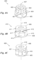
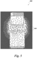
- FIG. 5 depicts a cross-sectional view of a mixing system 500 showing the magnetic coupling 501 in embodiments disclosed herein when using the pie-shaped magnets and back irons, as described in FIG. 4B .
- a back iron may be added on one of the impeller end or the drive end.
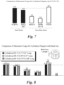
- the back iron added at impeller and drive ends improves torque production, as illustrated in FIG. 8 .
- FIG. 8 demonstrates the comparison of maximum torque for cylindrical magnets with back iron, as represented in FIG. 4C .
- FIG. 8 shows that maximum torque produced by different types of magnets (e.g., N 38/15, SmCo 28/7, etc.) as a function of magnet geometry.
- the ferrite magnet grade FB12H gives twice the amount of the torque produced without the back plate, while eliminating the use of rare earth magnets. Three of the magnet grades are not able to produce the baseline torque of the rare earth magnets.
- Embodiments of the invention modify the shape of the magnets from cylindrical to pie-shaped configurations.
- the improved impeller-drive design provides 2.5 times the torque without the need for expensive Neodymium magnets.
- Ferrite magnet grade FB12H gives 2.5 times the amount of torque produced without the back plate and the magnet pie shape.
- Embodiments of the invention provide an axial flux stator to reduce the drive end size, as well as reducing the number of components, and increase its reliability.
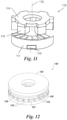
- FIG. 11 depicts an embodiment of the axial flux stator 110 without the shaft and bearing, and without the lever mechanism as utilized in the prior art.
- the drive stator 111 is positioned on an underside of the magnets 112 of the impeller end 114, aligned along a central axis of rotation 172, and has a control circuit 113.
- Windings can also be single or multi-layer, wave or lap windings, full or short pitched windings.
- the stationary steel segments can have additional slotting to accommodate magnetic gearing (e.g., Vernier type machine) with single or multi-stage gearing.
- the stator can also have additional magnets when using a Vernier type machine.
- FIG. 16A illustrates an embodiment of a tooth wound axial flux stator 160 with nine (9) slots 165 (See FIG. 16C ), for exemplary purposes, and not limitation.
- FIGS. 16B, 16C, and 16D depict perspective views to more clearly illustrate the details of the axial flux stator 160.
- the stator core comprises pie-shaped magnetic stator teeth 163 that extend vertically from the stator back iron 162.
- the stator core 170 can be formed from sintered powdered iron, ferrite, or machined from a coil of magnetic steel.
- Conductive windings (current carrying elements) 164 are wound around the stator teeth 163. The conductive windings are divided up into phases.
- the sense, field direction, of the individual coils alternates so that the application of phase current to the phase winding creates a magnetic field that is directed vertically upward in one tooth and vertically downward in another tooth.
- the flow of current through the conductive windings forms a magnetic field that flows through the stator teeth, across the air gap between the stator 160 and a rotor 161 capable of rotating around central axis 172, interacts with the magnets 166 on the rotor, travels through the rotor 161, and returns through a rotor magnet of opposite magnetic polarity, across the air gap between the stator and rotor, through an oppositely-excited stator tooth, closing through the stator back iron 162.
- the exemplary stator has nine slots 165 of width of about 0.470in (1.2 cm); the inside diameter (a hollow core 171 with central axis 172) of the stator core 170 is about 1.575in (4.0 cm), and the outside diameter of the stator core is about 3.250in (8.25 cm).
- the width of the slots, the core inside diameter, and core outside diameter are parameters that determine the performance of the motor.
- FIG. 16C depicts the magnetic stator core 170 including stator teeth 163 in combination with the base back iron 162 and shows that the stator core is about 2.750in (7.0 cm) height, but can vary in size, shape and dimension, as desired for a particular mixer.
- the stator core 175 is defined with conic teeth 176 and including a back iron 177.
- the stator core may be modified and designed to provide operational efficiency of a mixer.
- FIG. 10 compares torque versus current density of the axial flux stator 160 for gaps of about 0.32 inches (0.81 cm) and about 0.265 inches (0.67 cm) between the stator and rotor. More torque is produced for a given current density with the smaller gap. The efficiency is slightly greater for the smaller gap since the current is smaller.
- the cheaper impeller as described comprises a magnetic coupling improved by increasing the magnetic field density.
- Higher torque density is produced by optimizing the impeller magnet by way of material, shape, and back iron, individually or in combination.
- the rare earth magnets can be replaced by less expensive and environmentally friendly non-rare earth materials, such as Alnico and Ferrite, for example.
- the large and oversized drive assembly used prior now can run a much smaller impeller. Further, the moving parts on the drive side, near the user have been repositioned to provide a safer device overall.
- the more reliable system that includes the axial flux stator includes the axial flux stator; the axial flux stator has a smaller drive, no moving parts, and reduced magnetic force during bag installation. While cost and availability of the magnets is an advantage with improving magnet shape and material, the efficiency of the magnetic coupling that increase torque is very useful for further intensification of the bioreactor, various mixing systems, and overall efficiency.
- Torque produced in the mixing process relates to different fluid properties such as viscosity and density. Torque also relates to different mixing conditions such as presence of obstacles and changes or issue with gas sparging. For example, disruption of the continuous liquid or sparger liquid by zones of air presents large bubbles or channels, a behavior typically called [gas] flooding of the mixer; this leads to a drastic reduction of power input.
- a torque measurement i.e. a continuous measurement in real time
- a torque measurement under conditions close to or at the point of flooding of the mixer allows for better process control and higher utilization of mixing power, including improved capacity and capability in the process step. For example, a bioreactor could operate at higher mass transfer and thus higher productivity.
- torque measurements along with speed, enable determination of power transmitted to fluid by actual measurement, in contrast to using solely empirical impeller power number and speed, and thus allow actual mass transfer determination (i.e., gas transfer calculations).
- embodiments refer to a torque and speed sensor, such as a transducer, and a method of using the measured torque and speed to detect the different fluid and mixing properties, conditions, and abnormalities.
- Embodiments of the invention disclosed allow the power consumed by a rotating impeller to be easily measured in a process fluid.
- the units express this power as 'horsepower' (HP).
- Mixer performance relates to horsepower; problems, however are associated with this tendency.
- the power number ( N p ) is constant for each impeller type, as long as the Reynolds number is sufficiently high.
- the power number is a function of Reynolds Number (N re ).
- the Reynolds number is the indicator of the type of mixing fluid in which the mixer will operate. If the Reynolds Number is above 2,000, the power number is constant, When the Reynolds Number calculated is less than 1,000 (i.e., laminar flow), then the power number increases as the Reynolds Number decreases. Consequently, the shaft horsepower calculated is based on the corrected power number. In this case, as shown in FIG. 18 , a power number ( N p ) vs Reynolds Number ( N re ) curve is obtained from the impeller manufacturer or by experimentation.
- the power utilized to mix a fluid at a given speed can vary based on multiple parameters, including but not limited to: (i) the impeller diameter, (ii) the impeller blade design, (iii) the fluid properties (i.e. viscosity and density).
- controlling the power delivered to the fluid is an element of the mixing process. Since the mixing power is driven by the drive system, it can be measured and controlled from that side.
- the drive system can be in the form of a stator that rotates the impeller, or a set of magnets coupled to the impeller magnets and driven by a separate motor.
- the magnetic field that couples the drive to the impeller depends on the power (and also torque) delivered to the impeller.
- the torque, speed, and power delivered to the impeller can be calculated and hence controlled.
- the current and voltage inputs to the drive system are related to the power delivered to the system. These values can also be used to calculate the power delivered to the impeller.
- Table 1 shows the general properties of each fluid (at 25°C) while Table 2 shows the impeller and tank properties.
- Table 1 Property Water Fluid #1 Fluid #2 Fluid #3 Fluid #4 Fluid #5 Fluid #6 Fluid Density, ⁇ [kg/m 3 ] 1000 1000 1000 1000 1100 1300 1500 Dynamic Viscosity, ⁇ [Pa.s] 0.00089 0.0089 0.089 0.89 0.00089 0.00089 0.00089 0.00089 Table 2 Property Value Impeller Diameter [in] 3.5 Tank Volume [Lit] 200
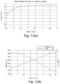
- FIG. 19 shows the variation of impeller torque as a function of rotating speed for Fluids 1, 2, 3, and water.
- the viscosity is the variable parameter in this calculation. Fluid 1 does not show detectable variation from water, while Fluid 2 and Fluid 3 show differences due to the increase in viscosity (100 times for Fluid 2 and 1000 times for Fluid 3).
- FIG. 20 shows the variation in torque-speed slope for different viscosities.
- the variation in slope is minimal when varying the viscosity, while the variation in y-axis crossing point is differentiated. Again, Fluids 1, 2, 3, and water are plotted; Fluid 1 does not show detectable variation from water.
- FIG. 21B shows the variation in torque-speed slope for different fluid densities of Fluids 4, 5, and 6 as compared to water. While the variation in slope due to viscosity is minimal, the density effects the slope, and minimally, the y-axis intercept.
- the change of viscosity in a fluid may be detected by measuring the impeller torque at different speeds.
- changes in density are detectable at various levels.
- the variation in fluid properties can be distinguished between variations in viscosity or density.
- Embodiments below describe the method of measuring the torque for bioreactors and various types of mixers.
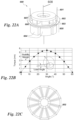
- a flux sensor such as the PCB winding 602 (shown in FIG. 22C ) is installed on an existing magnet-magnet coupling of a bioreactor, or mixer system, to acquire flux information and estimate torque.
- the flux sensor functions to acquire the speed by relating the measured voltage to the speed of rotation. The voltage, as it changes with time, is measured at various instances.
- FIG. 22C the illustration depicts a PCB winding 602 that picks up the back electro-motive force (EMF).
- EMF back electro-motive force
Landscapes
- Chemical & Material Sciences (AREA)
- Engineering & Computer Science (AREA)
- Health & Medical Sciences (AREA)
- Wood Science & Technology (AREA)
- Life Sciences & Earth Sciences (AREA)
- Bioinformatics & Cheminformatics (AREA)
- Organic Chemistry (AREA)
- Zoology (AREA)
- Chemical Kinetics & Catalysis (AREA)
- Power Engineering (AREA)
- General Engineering & Computer Science (AREA)
- Sustainable Development (AREA)
- Microbiology (AREA)
- Biochemistry (AREA)
- Biotechnology (AREA)
- General Health & Medical Sciences (AREA)
- Genetics & Genomics (AREA)
- Biomedical Technology (AREA)
- Analytical Chemistry (AREA)
- Computer Hardware Design (AREA)
- Clinical Laboratory Science (AREA)
- Mixers With Rotating Receptacles And Mixers With Vibration Mechanisms (AREA)
- Structures Of Non-Positive Displacement Pumps (AREA)
- Connection Of Motors, Electrical Generators, Mechanical Devices, And The Like (AREA)
- External Artificial Organs (AREA)
- Permanent Magnet Type Synchronous Machine (AREA)
- Accessories For Mixers (AREA)
- Dynamo-Electric Clutches, Dynamo-Electric Brakes (AREA)
- Mixers Of The Rotary Stirring Type (AREA)
Applications Claiming Priority (5)
| Application Number | Priority Date | Filing Date | Title |
|---|---|---|---|
| US15/087,712 US10583409B2 (en) | 2016-03-31 | 2016-03-31 | Axial flux stator |
| US15/087,656 US10335750B2 (en) | 2016-03-31 | 2016-03-31 | Magnetic drive for bioreactor |
| US15/166,397 US10682618B2 (en) | 2016-05-27 | 2016-05-27 | System and method for characterizing conditions in a fluid mixing device |
| PCT/US2017/021412 WO2017172316A1 (fr) | 2016-03-31 | 2017-03-08 | Mélangeurs magnétiques |
| EP17712626.5A EP3437177B1 (fr) | 2016-03-31 | 2017-03-08 | Mélangeur magnétique pour bioréacteur |
Related Parent Applications (2)
| Application Number | Title | Priority Date | Filing Date |
|---|---|---|---|
| EP17712626.5A Division-Into EP3437177B1 (fr) | 2016-03-31 | 2017-03-08 | Mélangeur magnétique pour bioréacteur |
| EP17712626.5A Division EP3437177B1 (fr) | 2016-03-31 | 2017-03-08 | Mélangeur magnétique pour bioréacteur |
Publications (2)
| Publication Number | Publication Date |
|---|---|
| EP4397403A2 true EP4397403A2 (fr) | 2024-07-10 |
| EP4397403A3 EP4397403A3 (fr) | 2024-10-23 |
Family
ID=58387931
Family Applications (2)
| Application Number | Title | Priority Date | Filing Date |
|---|---|---|---|
| EP24156493.9A Pending EP4397403A3 (fr) | 2016-03-31 | 2017-03-08 | Mélangeurs magnétiques |
| EP17712626.5A Active EP3437177B1 (fr) | 2016-03-31 | 2017-03-08 | Mélangeur magnétique pour bioréacteur |
Family Applications After (1)
| Application Number | Title | Priority Date | Filing Date |
|---|---|---|---|
| EP17712626.5A Active EP3437177B1 (fr) | 2016-03-31 | 2017-03-08 | Mélangeur magnétique pour bioréacteur |
Country Status (4)
| Country | Link |
|---|---|
| EP (2) | EP4397403A3 (fr) |
| JP (2) | JP7562200B2 (fr) |
| CN (2) | CN114699971A (fr) |
| WO (1) | WO2017172316A1 (fr) |
Families Citing this family (4)
| Publication number | Priority date | Publication date | Assignee | Title |
|---|---|---|---|---|
| DE112019003800T5 (de) * | 2018-07-27 | 2021-04-15 | Sumitomo Electric Industries, Ltd. | Kern, stator, und rotierende elektrische maschine |
| CN111224474B (zh) * | 2018-11-27 | 2022-08-19 | 深圳核心医疗科技有限公司 | 盘式电机 |
| CN112619508A (zh) * | 2020-12-19 | 2021-04-09 | 西藏晟源环境工程有限公司 | 一种基于磁力的实验搅拌设备 |
| CN112494803B (zh) * | 2020-12-22 | 2024-09-17 | 深圳核心医疗科技股份有限公司 | 血泵 |
Family Cites Families (28)
| Publication number | Priority date | Publication date | Assignee | Title |
|---|---|---|---|---|
| US2990253A (en) * | 1959-05-21 | 1961-06-27 | Miles Lab | Diagnostic composition |
| GB2139354A (en) * | 1983-05-03 | 1984-11-07 | British Hydromechanics | Monitoring process conditions |
| JPS60135041U (ja) * | 1984-02-17 | 1985-09-07 | 株式会社フジクラ | 電気回路兼磁気回路用基板 |
| JPS61212275A (ja) * | 1985-03-16 | 1986-09-20 | Shibaura Eng Works Co Ltd | アクチユエ−タ付きバイオリアクタ |
| JPH06109031A (ja) * | 1992-09-22 | 1994-04-19 | Nippondenso Co Ltd | 電磁クラッチ |
| US5608317A (en) * | 1994-06-21 | 1997-03-04 | Hughes Electronics | Complementary linear magnetic position sensor |
| US6890492B1 (en) * | 1998-08-13 | 2005-05-10 | Symyx Technologies, Inc. | Parallel reactor with internal sensing and method of using same |
| JP4340343B2 (ja) * | 1998-10-20 | 2009-10-07 | 慎一 秋山 | 磁気回転撹拌装置 |
| JP3609993B2 (ja) * | 2000-08-21 | 2005-01-12 | 利晃 島田 | 駆動軸の移動装置 |
| EP1188474B1 (fr) * | 2000-09-13 | 2004-10-06 | Levitronix LLC | Agitateur magnétique |
| CA2552717C (fr) * | 2004-01-07 | 2011-11-29 | Levtech, Inc. | Sac melangeur a arroseur integre et receptacle pour detecteur |
| US8471425B2 (en) * | 2011-03-09 | 2013-06-25 | Novatorque, Inc. | Rotor-stator structures including boost magnet structures for magnetic regions having angled confronting surfaces in rotor assemblies |
| CN1864839A (zh) * | 2006-04-17 | 2006-11-22 | 王丽军 | 智能加热搅拌器及其控制方法 |
| JP4940859B2 (ja) * | 2006-09-27 | 2012-05-30 | ダイキン工業株式会社 | コア、電機子、アキシャルギャップ型モータ、圧縮機、コアの製造方法、及び電機子の製造方法 |
| DE202007000665U1 (de) * | 2007-01-15 | 2008-05-29 | AMTEC - Anwendungszentrum für Mikrotechnologien Chemnitz GmbH | Magnetrührsystem |
| US7707916B2 (en) * | 2008-04-30 | 2010-05-04 | Alex Parsa Pirseyedi | Adjustable socket |
| NL2002417C2 (en) * | 2009-01-15 | 2010-07-19 | Avantium Holding B V | Stir system. |
| JP2010209963A (ja) * | 2009-03-09 | 2010-09-24 | Railway Technical Res Inst | 磁気カップリングクラッチ付きフライホイール装置 |
| CN201400670Y (zh) * | 2009-03-27 | 2010-02-10 | 镇江科海生物工程设备有限公司 | 磁耦合传动的发酵罐搅拌器 |
| JP5576246B2 (ja) | 2010-01-06 | 2014-08-20 | 株式会社神戸製鋼所 | アキシャルギャップ型ブラシレスモータ |
| CN202030764U (zh) * | 2011-05-06 | 2011-11-09 | 安徽丰原生物化学股份有限公司 | 发酵瓶及包括该发酵瓶的生物发酵培养装置 |
| WO2013040161A1 (fr) * | 2011-09-16 | 2013-03-21 | Xcellerex, Inc. | Systèmes de bioréacteur et de mélange à usage unique |
| CN202465713U (zh) * | 2012-03-15 | 2012-10-03 | 上海山富科学仪器有限公司 | 低速细胞培养搅拌系统 |
| US9415529B2 (en) * | 2012-05-08 | 2016-08-16 | Basf Se | Method for operating an apparatus with at least one rotating shaft |
| FR2994018B1 (fr) * | 2012-07-27 | 2015-01-16 | Cooltech Applications | Generateur de champ magnetique pour appareil thermique magnetocalorique et appareil thermique magnetocalorique equipe d'un tel generateur |
| DE102012020384B4 (de) * | 2012-10-18 | 2014-07-10 | Sartorius Stedim Biotech Gmbh | Bioreaktor, Reaktorbeutel dafür und Rührer zur Umwälzung seines Inhaltes |
| US10213755B2 (en) * | 2014-08-15 | 2019-02-26 | Schlumberger Technology Corporation | Wellsite mixer sensing assembly and method of using same |
| CN105327639B (zh) | 2015-05-20 | 2018-01-30 | 江苏雷利电机股份有限公司 | 采用分体式直驱电机的搅拌机 |
-
2017
- 2017-03-08 EP EP24156493.9A patent/EP4397403A3/fr active Pending
- 2017-03-08 EP EP17712626.5A patent/EP3437177B1/fr active Active
- 2017-03-08 WO PCT/US2017/021412 patent/WO2017172316A1/fr not_active Ceased
- 2017-03-08 JP JP2018550547A patent/JP7562200B2/ja active Active
- 2017-03-08 CN CN202210372343.5A patent/CN114699971A/zh active Pending
- 2017-03-08 CN CN201780021341.9A patent/CN108886319B/zh active Active
-
2024
- 2024-06-05 JP JP2024091641A patent/JP2024133473A/ja active Pending
Also Published As
| Publication number | Publication date |
|---|---|
| EP3437177A1 (fr) | 2019-02-06 |
| JP2019513341A (ja) | 2019-05-23 |
| CN108886319B (zh) | 2022-04-12 |
| JP7562200B2 (ja) | 2024-10-07 |
| JP2024133473A (ja) | 2024-10-02 |
| EP3437177B1 (fr) | 2024-03-20 |
| CN108886319A (zh) | 2018-11-23 |
| WO2017172316A1 (fr) | 2017-10-05 |
| EP4397403A3 (fr) | 2024-10-23 |
| CN114699971A (zh) | 2022-07-05 |
Similar Documents
| Publication | Publication Date | Title |
|---|---|---|
| US11969701B2 (en) | Magnetic mixers | |
| JP2024133473A (ja) | 磁気ミキサ | |
| US10682618B2 (en) | System and method for characterizing conditions in a fluid mixing device | |
| US12172140B2 (en) | Mixing device having a stirring element | |
| US20050272146A1 (en) | Disposable bioreactor systems and methods | |
| AU2012308611B2 (en) | Single-use mixing and bioreactor systems | |
| US20170007973A1 (en) | Mixing apparatus and single-use apparatus for a mixing apparatus | |
| EP2544809B1 (fr) | Récipient pour poche de traitement doté de capteurs | |
| JP6363697B2 (ja) | 単回使用バイオリアクターにおける可撓性フィルムバッフル | |
| US10335750B2 (en) | Magnetic drive for bioreactor | |
| CN207659423U (zh) | 磁力搅拌生物反应器 | |
| CN202590702U (zh) | 一种带速度反馈超低速磁力搅拌器 | |
| US10583409B2 (en) | Axial flux stator | |
| CN218654167U (zh) | 一种方便测速的磁传动搅拌器 | |
| JPH0227881Y2 (fr) | ||
| CN214400303U (zh) | 一种电磁型水肥混合液体磁化器 | |
| Reichert et al. | Design study for exterior rotor bearingless permanent magnet machines | |
| CN121243825A (zh) | 一种磁力耦合真空脱气装置及气液分离方法 |
Legal Events
| Date | Code | Title | Description |
|---|---|---|---|
| PUAI | Public reference made under article 153(3) epc to a published international application that has entered the european phase |
Free format text: ORIGINAL CODE: 0009012 |
|
| STAA | Information on the status of an ep patent application or granted ep patent |
Free format text: STATUS: THE APPLICATION HAS BEEN PUBLISHED |
|
| AC | Divisional application: reference to earlier application |
Ref document number: 3437177 Country of ref document: EP Kind code of ref document: P |
|
| AK | Designated contracting states |
Kind code of ref document: A2 Designated state(s): AL AT BE BG CH CY CZ DE DK EE ES FI FR GB GR HR HU IE IS IT LI LT LU LV MC MK MT NL NO PL PT RO RS SE SI SK SM TR |
|
| PUAL | Search report despatched |
Free format text: ORIGINAL CODE: 0009013 |
|
| AK | Designated contracting states |
Kind code of ref document: A3 Designated state(s): AL AT BE BG CH CY CZ DE DK EE ES FI FR GB GR HR HU IE IS IT LI LT LU LV MC MK MT NL NO PL PT RO RS SE SI SK SM TR |
|
| RIC1 | Information provided on ipc code assigned before grant |
Ipc: H02K 5/128 20060101ALI20240918BHEP Ipc: H02K 1/14 20060101ALI20240918BHEP Ipc: H02K 49/10 20060101ALI20240918BHEP Ipc: B01F 35/222 20220101ALI20240918BHEP Ipc: B01F 35/22 20220101ALI20240918BHEP Ipc: B01F 35/21 20220101ALI20240918BHEP Ipc: B01F 35/212 20220101ALI20240918BHEP Ipc: B01F 33/45 20220101AFI20240918BHEP |
|
| STAA | Information on the status of an ep patent application or granted ep patent |
Free format text: STATUS: REQUEST FOR EXAMINATION WAS MADE |
|
| 17P | Request for examination filed |
Effective date: 20250423 |
|
| STAA | Information on the status of an ep patent application or granted ep patent |
Free format text: STATUS: EXAMINATION IS IN PROGRESS |
|
| 17Q | First examination report despatched |
Effective date: 20260319 |