EP4397464A1 - Machine de retrait d'étiquette - Google Patents
Machine de retrait d'étiquette Download PDFInfo
- Publication number
- EP4397464A1 EP4397464A1 EP22863468.9A EP22863468A EP4397464A1 EP 4397464 A1 EP4397464 A1 EP 4397464A1 EP 22863468 A EP22863468 A EP 22863468A EP 4397464 A1 EP4397464 A1 EP 4397464A1
- Authority
- EP
- European Patent Office
- Prior art keywords
- fixed blade
- disposed
- plates
- removing machine
- label removing
- Prior art date
- Legal status (The legal status is an assumption and is not a legal conclusion. Google has not performed a legal analysis and makes no representation as to the accuracy of the status listed.)
- Pending
Links
- 238000003756 stirring Methods 0.000 claims description 10
- 230000007246 mechanism Effects 0.000 claims description 8
- 239000004033 plastic Substances 0.000 description 18
- 238000010586 diagram Methods 0.000 description 5
- 238000004064 recycling Methods 0.000 description 5
- 238000000034 method Methods 0.000 description 3
- 230000008569 process Effects 0.000 description 3
- 125000006850 spacer group Chemical group 0.000 description 3
- 239000012634 fragment Substances 0.000 description 2
- 238000012986 modification Methods 0.000 description 2
- 230000004048 modification Effects 0.000 description 2
- XLYOFNOQVPJJNP-UHFFFAOYSA-N water Substances O XLYOFNOQVPJJNP-UHFFFAOYSA-N 0.000 description 2
- 241001122767 Theaceae Species 0.000 description 1
- 230000009471 action Effects 0.000 description 1
- 230000009286 beneficial effect Effects 0.000 description 1
- 235000013361 beverage Nutrition 0.000 description 1
- 230000000903 blocking effect Effects 0.000 description 1
- 230000000694 effects Effects 0.000 description 1
- 229910052500 inorganic mineral Inorganic materials 0.000 description 1
- 239000008267 milk Substances 0.000 description 1
- 210000004080 milk Anatomy 0.000 description 1
- 235000013336 milk Nutrition 0.000 description 1
- 239000011707 mineral Substances 0.000 description 1
- 239000002985 plastic film Substances 0.000 description 1
- 229920006255 plastic film Polymers 0.000 description 1
- 230000002035 prolonged effect Effects 0.000 description 1
- 239000002994 raw material Substances 0.000 description 1
- 238000006467 substitution reaction Methods 0.000 description 1
Images



Classifications
-
- B—PERFORMING OPERATIONS; TRANSPORTING
- B08—CLEANING
- B08B—CLEANING IN GENERAL; PREVENTION OF FOULING IN GENERAL
- B08B9/00—Cleaning hollow articles by methods or apparatus specially adapted thereto
- B08B9/08—Cleaning containers, e.g. tanks
-
- B—PERFORMING OPERATIONS; TRANSPORTING
- B08—CLEANING
- B08B—CLEANING IN GENERAL; PREVENTION OF FOULING IN GENERAL
- B08B9/00—Cleaning hollow articles by methods or apparatus specially adapted thereto
- B08B9/08—Cleaning containers, e.g. tanks
- B08B9/0804—Cleaning containers having tubular shape, e.g. casks, barrels, drums
- B08B9/0808—Cleaning containers having tubular shape, e.g. casks, barrels, drums by methods involving the use of tools, e.g. by brushes, scrapers
-
- B—PERFORMING OPERATIONS; TRANSPORTING
- B08—CLEANING
- B08B—CLEANING IN GENERAL; PREVENTION OF FOULING IN GENERAL
- B08B9/00—Cleaning hollow articles by methods or apparatus specially adapted thereto
- B08B9/08—Cleaning containers, e.g. tanks
- B08B9/0821—Handling or manipulating containers, e.g. moving or rotating containers in cleaning devices, conveying to or from cleaning devices
-
- B—PERFORMING OPERATIONS; TRANSPORTING
- B08—CLEANING
- B08B—CLEANING IN GENERAL; PREVENTION OF FOULING IN GENERAL
- B08B9/00—Cleaning hollow articles by methods or apparatus specially adapted thereto
- B08B9/08—Cleaning containers, e.g. tanks
- B08B9/083—Removing scrap from containers, e.g. removing labels
-
- B—PERFORMING OPERATIONS; TRANSPORTING
- B29—WORKING OF PLASTICS; WORKING OF SUBSTANCES IN A PLASTIC STATE IN GENERAL
- B29B—PREPARATION OR PRETREATMENT OF THE MATERIAL TO BE SHAPED; MAKING GRANULES OR PREFORMS; RECOVERY OF PLASTICS OR OTHER CONSTITUENTS OF WASTE MATERIAL CONTAINING PLASTICS
- B29B17/00—Recovery of plastics or other constituents of waste material containing plastics
- B29B17/02—Separating plastics from other materials
-
- B—PERFORMING OPERATIONS; TRANSPORTING
- B08—CLEANING
- B08B—CLEANING IN GENERAL; PREVENTION OF FOULING IN GENERAL
- B08B2209/00—Details of machines or methods for cleaning hollow articles
- B08B2209/08—Details of machines or methods for cleaning containers, e.g. tanks
-
- B—PERFORMING OPERATIONS; TRANSPORTING
- B29—WORKING OF PLASTICS; WORKING OF SUBSTANCES IN A PLASTIC STATE IN GENERAL
- B29B—PREPARATION OR PRETREATMENT OF THE MATERIAL TO BE SHAPED; MAKING GRANULES OR PREFORMS; RECOVERY OF PLASTICS OR OTHER CONSTITUENTS OF WASTE MATERIAL CONTAINING PLASTICS
- B29B17/00—Recovery of plastics or other constituents of waste material containing plastics
- B29B17/02—Separating plastics from other materials
- B29B2017/0213—Specific separating techniques
- B29B2017/0217—Mechanical separating techniques; devices therefor
-
- Y—GENERAL TAGGING OF NEW TECHNOLOGICAL DEVELOPMENTS; GENERAL TAGGING OF CROSS-SECTIONAL TECHNOLOGIES SPANNING OVER SEVERAL SECTIONS OF THE IPC; TECHNICAL SUBJECTS COVERED BY FORMER USPC CROSS-REFERENCE ART COLLECTIONS [XRACs] AND DIGESTS
- Y02—TECHNOLOGIES OR APPLICATIONS FOR MITIGATION OR ADAPTATION AGAINST CLIMATE CHANGE
- Y02W—CLIMATE CHANGE MITIGATION TECHNOLOGIES RELATED TO WASTEWATER TREATMENT OR WASTE MANAGEMENT
- Y02W30/00—Technologies for solid waste management
- Y02W30/50—Reuse, recycling or recovery technologies
- Y02W30/62—Plastics recycling; Rubber recycling
Definitions
- plastic bottles such as mineral water bottles, beverage bottles, tea water bottles and milk bottles.
- These plastic bottles usually have labels on the outside, and the labels are often made of plastic film.
- the labels on the outside of the plastic bottles need to be removed, and then bottle bodies are washed and crushed to produce recycled plastic raw materials.
- An existing label removing machine includes a base, a feeding seat, and a supporting seat.
- An outer cylinder is disposed between the feeding seat and the supporting seat.
- a rotary drum is disposed in the outer cylinder. The rotary drum is connected to a motor and driven by the motor, and able to rotate inside the outer cylinder.
- An annular space is formed between the outer cylinder and the inner cylinder.
- Moving blade components are disposed on an outer wall of the inner cylinder, and fixed blade components are disposed on an inner wall of the outer cylinder.
- the fixed blade components are of a large quantity and are densely distributed on the inner wall of the outer cylinder.
- the feeding seat is provided with a feeding inlet and a feeding chamber, and the feeding chamber communicates with the annular space between the outer cylinder and the inner cylinder.
- the plastic bottles are fed from the feeding inlet on the feeding seat, and enter the annular space between the outer cylinder and the inner cylinder via the feeding chamber, and labels outside the plastic bottles are torn off under the action of the fixed blade components and the moving blade components, so that the function of label removal is achieved.
- the fixed blade components may be worn, so the fixed blade components need to be replaced.
- the fixed blade components are of a large quantity, it is difficult to replace the fixed blade components one by one, and the replacement time is long.
- the object of the present invention is to solve the problems that during replacement of fixed blade components of an existing label removing machine, since the fixed blade components are of a large quantity, it is difficult to replace the fixed blade components one by one, and the replacement time is long, and to provide a label removing machine which may effectively solve the above-mentioned problems and has the characteristics of long service life and low recycling loss when in use.
- a label removing machine includes a base, a feeding seat and a supporting seat being disposed on the base, an outer cylinder being disposed between the feeding seat and the supporting seat, a rotary drum being disposed in the outer cylinder, moving blade components being disposed on an outer wall of the rotary drum, the outer cylinder including a supporting frame, a plurality of fixed blade plates being detachably connected to the supporting frame in a circumferential direction, a plurality of fixed blade components being detachably connected to the fixed blade plates.
- each fixed blade plate and the fixed blade components connected thereto form a module, so that when the fixed blade components need to be replaced, the whole module is directly replaced without replacing the fixed blade components one by one. Therefore, the replacement efficiency is greatly improved, the time required for replacement is shortened, and replacement is convenient.
- the fixed blade components are generally unilaterally worn, that is, one sides of the fixed blade components are heavily worn, while the other sides are almost not worn.
- the fixed blade plates may be horizontally rotated by 180 degrees, and the less worn sides of the fixed blade components continue to be used for operation, thereby effectively prolonging the service life of the fixed blade components and reducing the replacement frequency of the fixed blade components.
- the modular design concept of the present invention greatly facilitates the above operation.
- the supporting frame includes two end plates, a plurality of cross beams parallel to one another are disposed between the two end plates, each of the fixed blade plates is connected between two immediately adjacent cross beams, and fixing mechanisms for fixing the fixed blade plates are connected to the cross beams.
- the two ends of each fixed blade plate are respectively connected to the two immediately adjacent cross beams, and are fixed by the fixing mechanisms.
- each of the fixing mechanisms includes a batten and first bolts for connecting the batten to the corresponding cross beam, and a cross section of the batten is in a "U" shape; and the battens are provided with through holes allowing the first bolts to penetrate through, the cross beams are provided with threaded holes for connection to the first bolts, the first bolts penetrate through the through holes provided in the battens and are connected to the threaded holes in the cross beams, and the battens press one ends of the fixed blade plates against the connecting flanges.
- the fixed blade plates are convenient to install and remove.
- second install handles are disposed on the battens. Since the second install handles are disposed on the battens, the battens are convenient to install and remove.
- stirring battens are disposed on the outer wall of the rotary drum.
- the cross section of each of the stirring battens is triangular, and the stirring battens are disposed in the axial direction of the rotary drum.
- the stirring battens may stir plastic bottles to reduce the occurrence of blocking.
- the feeding seat is provided with a feeding chamber and a feeding inlet connected to the feeding chamber, and wear-resistant plates are detachably connected to an inner wall of the feeding chamber.
- the wear-resistant plates cover the inner wall of the feeding chamber, and are detachably connected to the inner wall of the feeding chamber, so that the wear-resistant plates are convenient to replace.
- the wear-resistant plates are connected to the inner wall of the feeding chamber through second bolts.
- each of the fixed blade components includes a fixed blade and a cap nut
- the fixed blade including a main body, a positioning platform being disposed on one side of the main body, and a cutter bit being disposed on the other side of the main body, studs being disposed on the positioning platforms, positioning through grooves matching the positioning platforms being provided in the fixed blade plates, the positioning platforms being connected to the positioning through grooves, the main bodies being located on one sides of the fixed blade plates, the cap nuts being connected to the studs on the other sides of the fixed blade plates.
- the main bodies are each in a disk shape, and the sides, close to the cutter bits, of the main bodies are spherical or quasi-spherical.
- the cross sections of the positioning platforms 22 and the positioning through grooves 17 are respectively square.
- a spacer is further disposed between each of the cap nuts and the fixed blade plate.
- the function of the cap nuts is to fix the fixed blades onto the fixed blade plates.
- the cutter bits are in contact with labels on the outside of the plastic bottles to tear the labels, so as to separate the labels from the bottles. Since the fixed blades are connected to the fixed blade plates by matching with the cap nuts, the fixed blades are convenient to install and remove.
- the worn sides of the cutter bits may be rotated to other angles by adjusting the angle of the fixed blades, and unworn portions of the cutter bits continue to be used for operation, so that the service life of the fixed blades is greatly prolonged, the replacement frequency of the fixed blades is reduced, and replacement costs are saved.
- the fixed blades match the positioning through grooves in the fixed blade plates via the positioning platforms disposed on the fixed blades, and the cross sections of the positioning platforms and the positioning through grooves are respectively square, the minimum adjustment angle of the fixed blades is 90 degrees.
- label removing machine bolts serve as positioning components.
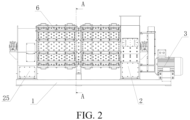
- a label removing machine includes a base 1, and a supporting seat 25 and a feeding seat 2 are disposed on the base 1.
- An outer cylinder is disposed between the feeding seat 2 and the supporting seat 25.
- a rotary drum 11 is disposed in the outer cylinder.
- a motor 3 for driving the rotary drum 11 to rotate is disposed on the base 1.
- An annular space is formed between the outer cylinder and the rotary drum 1.
- Moving blade components 12 and stirring battens 16 are disposed on an outer wall of the rotary drum 11. The cross section of each of the stirring battens 16 is triangular, and the stirring battens 16 are disposed in the axial direction of the rotary drum 11.
- the outer cylinder includes a supporting frame, and a plurality of fixed blade plates 6 are detachably connected to the supporting frame in the circumferential direction.
- the fixed blade plates 6 are each of a rectangular plate structure.
- the supporting frame includes two end plates 4.
- a plurality of cross beams 5 parallel to one another are disposed between the two end plates 4.
- the fixed blade plates 6 are connected between two immediately adjacent cross beams 5.
- Fixing mechanisms for fixing the fixed blade plates 6 are connected to the cross beams 5.
- Two sides of the cross beams 5 are respectively provided with connecting flanges, and one ends of the fixed blade plates 6 abut against the connecting flanges.
- Each of the fixing mechanisms includes a batten 8 and first bolts 9 for connecting the batten 8 to the corresponding cross beam 5.
- each of the battens 8 is in a "U" shape.
- the battens 8 are provided with through holes allowing the first bolts 9 to penetrate through.
- the cross beams 5 are provided with threaded holes for connection to the first bolts.
- the first bolts 9 penetrate through the through holes provided in the battens 8 and are connected to the threaded holes in the cross beams 5.
- the battens 8 press one ends of the fixed blade plates 6 against the connecting flanges. Second install handles 10 are disposed on the battens 8.
- the positioning platforms 22 are connected to the positioning through grooves 17.
- the main bodies are located on one sides of the fixed blade plates 6, and the cap nuts 19 are connected to the studs 23 on the other sides of the fixed blade plates 6.
- the main bodies are each in a disk shape, and the sides, close to the cutter bits, of the main bodies are spherical or quasi-spherical.
- a spacer 20 is further provided between each of the cap nuts 19 and the corresponding fixed blade plate 6.
- First install handles 7 are disposed on the fixed blade plates 6.
- the cross sections of the positioning platforms 22 and the positioning through grooves 17 are respectively square.
- each fixed blade plate and the fixed blade components connected thereto form a module, so that when the fixed blade components need to be replaced, the whole module is directly replaced without replacing the fixed blade components one by one. Therefore, the replacement efficiency is greatly improved, the time required for replacement is shortened, and replacement is convenient.
- the fixed blade components are generally unilaterally worn, that is, one sides of the fixed blade components are heavily worn, while the other sides are almost not worn.
Landscapes
- Engineering & Computer Science (AREA)
- Mechanical Engineering (AREA)
- Environmental & Geological Engineering (AREA)
- Crushing And Pulverization Processes (AREA)
- Details Of Cutting Devices (AREA)
Applications Claiming Priority (3)
| Application Number | Priority Date | Filing Date | Title |
|---|---|---|---|
| CN202122086385.6U CN216267037U (zh) | 2021-08-30 | 2021-08-30 | 脱标机 |
| CN202111005423.9A CN113696378A (zh) | 2021-08-30 | 2021-08-30 | 一种脱标机 |
| PCT/CN2022/115899 WO2023030333A1 (fr) | 2021-08-30 | 2022-08-30 | Machine de retrait d'étiquette |
Publications (2)
| Publication Number | Publication Date |
|---|---|
| EP4397464A1 true EP4397464A1 (fr) | 2024-07-10 |
| EP4397464A4 EP4397464A4 (fr) | 2024-12-11 |
Family
ID=85410870
Family Applications (1)
| Application Number | Title | Priority Date | Filing Date |
|---|---|---|---|
| EP22863468.9A Pending EP4397464A4 (fr) | 2021-08-30 | 2022-08-30 | Machine de retrait d'étiquette |
Country Status (4)
| Country | Link |
|---|---|
| US (1) | US20240075506A1 (fr) |
| EP (1) | EP4397464A4 (fr) |
| MX (1) | MX2023010152A (fr) |
| WO (1) | WO2023030333A1 (fr) |
Families Citing this family (1)
| Publication number | Priority date | Publication date | Assignee | Title |
|---|---|---|---|---|
| CN119713800B (zh) * | 2025-02-28 | 2025-04-29 | 海盐伟成印刷股份有限公司 | 一种标签用全彩织锦生产的烘干设备 |
Family Cites Families (12)
| Publication number | Priority date | Publication date | Assignee | Title |
|---|---|---|---|---|
| DE2246059C2 (de) * | 1972-09-20 | 1985-05-02 | Klöckner-Humboldt-Deutz AG, 5000 Köln | Innenpanzerung für Prallbrecher |
| US4222865A (en) * | 1979-02-16 | 1980-09-16 | Irathane Systems Incorporated | Trommel screen unit |
| US5203359A (en) * | 1991-11-04 | 1993-04-20 | Ellis Corporation | Unitary system for recycling used contaminated material for re-use |
| CA2628036C (fr) * | 2001-10-16 | 2012-05-15 | Merlin Plastics Alberta Inc. | Systeme pour decoller les etiquettes et separateur etiquettes-contenants |
| CN202029274U (zh) * | 2011-01-11 | 2011-11-09 | 盈创再生资源有限公司 | 自动脱标器 |
| CN103350464B (zh) * | 2013-07-30 | 2015-10-14 | 浙江宝绿特环保技术有限公司 | 连续式自动标签剥离设备 |
| CN203527697U (zh) * | 2013-08-30 | 2014-04-09 | 上海申嘉三和环保科技开发有限公司 | 塑料瓶除标机 |
| CN111589813A (zh) * | 2020-04-21 | 2020-08-28 | 浙江宝绿特环保技术工程有限公司 | 脱标机中钨钢刀头的安装结构 |
| CN113696378A (zh) * | 2021-08-30 | 2021-11-26 | 浙江宝绿特环保技术工程有限公司 | 一种脱标机 |
| CN216267037U (zh) * | 2021-08-30 | 2022-04-12 | 浙江宝绿特环保技术工程有限公司 | 脱标机 |
| CN216230247U (zh) * | 2021-09-17 | 2022-04-08 | 浙江宝绿特环保技术工程有限公司 | 一种整瓶脱标清洗一体化系统 |
| CN113858485A (zh) * | 2021-09-17 | 2021-12-31 | 浙江宝绿特环保技术工程有限公司 | 一种整瓶脱标清洗一体化系统 |
-
2022
- 2022-08-30 US US18/270,699 patent/US20240075506A1/en active Pending
- 2022-08-30 MX MX2023010152A patent/MX2023010152A/es unknown
- 2022-08-30 WO PCT/CN2022/115899 patent/WO2023030333A1/fr not_active Ceased
- 2022-08-30 EP EP22863468.9A patent/EP4397464A4/fr active Pending
Also Published As
| Publication number | Publication date |
|---|---|
| US20240075506A1 (en) | 2024-03-07 |
| MX2023010152A (es) | 2023-09-11 |
| WO2023030333A1 (fr) | 2023-03-09 |
| EP4397464A4 (fr) | 2024-12-11 |
Similar Documents
| Publication | Publication Date | Title |
|---|---|---|
| US5975443A (en) | Waste recycling device | |
| US5150844A (en) | Apparatus for size reduction of heavy solid waste materials | |
| EP4397464A1 (fr) | Machine de retrait d'étiquette | |
| CN102658229A (zh) | 一种破碎机 | |
| US7004413B2 (en) | Grinder cutter tooth and anvil assembly | |
| US20090189004A1 (en) | Comminuting device with counter-rotating rotors | |
| CN216267037U (zh) | 脱标机 | |
| CN113083467A (zh) | 一种用于固体废弃物处理的破碎机 | |
| CN218690134U (zh) | 一种用于极片软包高效破拆的双轴切碎机 | |
| CN208146149U (zh) | 一种粉碎机 | |
| US6196284B1 (en) | Wood pulverizer with improved grates and grate components | |
| CN101507935B (zh) | 锤片式粉碎机 | |
| CN222918776U (zh) | 一种用于死畜禽尸体的破碎机 | |
| CN218554287U (zh) | 一种垃圾破分装置 | |
| CN216727517U (zh) | 一种高效率纸管破碎机 | |
| KR200266269Y1 (ko) | 저속 분쇄기 | |
| CN215843308U (zh) | 一种锤式破碎机及破碎生产线 | |
| CN210928699U (zh) | 一种组合式秸秆粉碎机 | |
| CN117059936A (zh) | 废旧钠离子电池的拆解分选装置及工艺 | |
| CN215312909U (zh) | 一种用于固体废弃物处理的破碎机 | |
| KR200254467Y1 (ko) | 재활용 캔 분쇄장치 | |
| CN113696378A (zh) | 一种脱标机 | |
| KR20190129442A (ko) | 칩 파쇄기 | |
| JPH11114437A (ja) | シュレッダ及びハンマミル用回転子 | |
| CN220634697U (zh) | 一种粉碎机进料结构 |
Legal Events
| Date | Code | Title | Description |
|---|---|---|---|
| STAA | Information on the status of an ep patent application or granted ep patent |
Free format text: STATUS: THE INTERNATIONAL PUBLICATION HAS BEEN MADE |
|
| PUAI | Public reference made under article 153(3) epc to a published international application that has entered the european phase |
Free format text: ORIGINAL CODE: 0009012 |
|
| STAA | Information on the status of an ep patent application or granted ep patent |
Free format text: STATUS: REQUEST FOR EXAMINATION WAS MADE |
|
| 17P | Request for examination filed |
Effective date: 20230808 |
|
| AK | Designated contracting states |
Kind code of ref document: A1 Designated state(s): AL AT BE BG CH CY CZ DE DK EE ES FI FR GB GR HR HU IE IS IT LI LT LU LV MC MK MT NL NO PL PT RO RS SE SI SK SM TR |
|
| DAV | Request for validation of the european patent (deleted) | ||
| DAX | Request for extension of the european patent (deleted) | ||
| A4 | Supplementary search report drawn up and despatched |
Effective date: 20241112 |
|
| RIC1 | Information provided on ipc code assigned before grant |
Ipc: B08B 9/08 20060101ALI20241106BHEP Ipc: B29B 17/00 20060101ALI20241106BHEP Ipc: B29B 17/02 20060101AFI20241106BHEP |