EP4397518A1 - Moteur-roue - Google Patents
Moteur-roue Download PDFInfo
- Publication number
- EP4397518A1 EP4397518A1 EP22864035.5A EP22864035A EP4397518A1 EP 4397518 A1 EP4397518 A1 EP 4397518A1 EP 22864035 A EP22864035 A EP 22864035A EP 4397518 A1 EP4397518 A1 EP 4397518A1
- Authority
- EP
- European Patent Office
- Prior art keywords
- housing
- stator
- wheel
- wheel motor
- rotor
- Prior art date
- Legal status (The legal status is an assumption and is not a legal conclusion. Google has not performed a legal analysis and makes no representation as to the accuracy of the status listed.)
- Pending
Links
Images


Classifications
-
- B—PERFORMING OPERATIONS; TRANSPORTING
- B60—VEHICLES IN GENERAL
- B60K—ARRANGEMENT OR MOUNTING OF PROPULSION UNITS OR OF TRANSMISSIONS IN VEHICLES; ARRANGEMENT OR MOUNTING OF PLURAL DIVERSE PRIME-MOVERS IN VEHICLES; AUXILIARY DRIVES FOR VEHICLES; INSTRUMENTATION OR DASHBOARDS FOR VEHICLES; ARRANGEMENTS IN CONNECTION WITH COOLING, AIR INTAKE, GAS EXHAUST OR FUEL SUPPLY OF PROPULSION UNITS IN VEHICLES
- B60K7/00—Disposition of motor in, or adjacent to, traction wheel
- B60K7/0007—Disposition of motor in, or adjacent to, traction wheel the motor being electric
-
- H—ELECTRICITY
- H02—GENERATION; CONVERSION OR DISTRIBUTION OF ELECTRIC POWER
- H02K—DYNAMO-ELECTRIC MACHINES
- H02K11/00—Structural association of dynamo-electric machines with electric components or with devices for shielding, monitoring or protection
- H02K11/30—Structural association with control circuits or drive circuits
- H02K11/33—Drive circuits, e.g. power electronics
-
- H—ELECTRICITY
- H02—GENERATION; CONVERSION OR DISTRIBUTION OF ELECTRIC POWER
- H02K—DYNAMO-ELECTRIC MACHINES
- H02K21/00—Synchronous motors having permanent magnets; Synchronous generators having permanent magnets
- H02K21/12—Synchronous motors having permanent magnets; Synchronous generators having permanent magnets with stationary armatures and rotating magnets
- H02K21/14—Synchronous motors having permanent magnets; Synchronous generators having permanent magnets with stationary armatures and rotating magnets with magnets rotating within the armatures
-
- H—ELECTRICITY
- H02—GENERATION; CONVERSION OR DISTRIBUTION OF ELECTRIC POWER
- H02K—DYNAMO-ELECTRIC MACHINES
- H02K5/00—Casings; Enclosures; Supports
- H02K5/04—Casings or enclosures characterised by the shape, form or construction thereof
- H02K5/16—Means for supporting bearings, e.g. insulating supports or means for fitting bearings in the bearing-shields
- H02K5/173—Means for supporting bearings, e.g. insulating supports or means for fitting bearings in the bearing-shields using bearings with rolling contact, e.g. ball bearings
- H02K5/1737—Means for supporting bearings, e.g. insulating supports or means for fitting bearings in the bearing-shields using bearings with rolling contact, e.g. ball bearings radially supporting the rotor around a fixed spindle; radially supporting the rotor directly
-
- H—ELECTRICITY
- H02—GENERATION; CONVERSION OR DISTRIBUTION OF ELECTRIC POWER
- H02K—DYNAMO-ELECTRIC MACHINES
- H02K7/00—Arrangements for handling mechanical energy structurally associated with dynamo-electric machines, e.g. structural association with mechanical driving motors or auxiliary dynamo-electric machines
- H02K7/08—Structural association with bearings
- H02K7/086—Structural association with bearings radially supporting the rotor around a fixed spindle; radially supporting the rotor directly
- H02K7/088—Structural association with bearings radially supporting the rotor around a fixed spindle; radially supporting the rotor directly radially supporting the rotor directly
-
- H—ELECTRICITY
- H02—GENERATION; CONVERSION OR DISTRIBUTION OF ELECTRIC POWER
- H02K—DYNAMO-ELECTRIC MACHINES
- H02K7/00—Arrangements for handling mechanical energy structurally associated with dynamo-electric machines, e.g. structural association with mechanical driving motors or auxiliary dynamo-electric machines
- H02K7/10—Structural association with clutches, brakes, gears, pulleys or mechanical starters
- H02K7/102—Structural association with clutches, brakes, gears, pulleys or mechanical starters with friction brakes
-
- B—PERFORMING OPERATIONS; TRANSPORTING
- B60—VEHICLES IN GENERAL
- B60G—VEHICLE SUSPENSION ARRANGEMENTS
- B60G2204/00—Indexing codes related to suspensions per se or to auxiliary parts
- B60G2204/10—Mounting of suspension elements
- B60G2204/14—Mounting of suspension arms
- B60G2204/148—Mounting of suspension arms on the unsprung part of the vehicle, e.g. wheel knuckle or rigid axle
-
- B—PERFORMING OPERATIONS; TRANSPORTING
- B60—VEHICLES IN GENERAL
- B60G—VEHICLE SUSPENSION ARRANGEMENTS
- B60G7/00—Pivoted suspension arms; Accessories thereof
- B60G7/008—Attaching arms to unsprung part of vehicle
-
- B—PERFORMING OPERATIONS; TRANSPORTING
- B60—VEHICLES IN GENERAL
- B60K—ARRANGEMENT OR MOUNTING OF PROPULSION UNITS OR OF TRANSMISSIONS IN VEHICLES; ARRANGEMENT OR MOUNTING OF PLURAL DIVERSE PRIME-MOVERS IN VEHICLES; AUXILIARY DRIVES FOR VEHICLES; INSTRUMENTATION OR DASHBOARDS FOR VEHICLES; ARRANGEMENTS IN CONNECTION WITH COOLING, AIR INTAKE, GAS EXHAUST OR FUEL SUPPLY OF PROPULSION UNITS IN VEHICLES
- B60K7/00—Disposition of motor in, or adjacent to, traction wheel
- B60K2007/0038—Disposition of motor in, or adjacent to, traction wheel the motor moving together with the wheel axle
-
- B—PERFORMING OPERATIONS; TRANSPORTING
- B60—VEHICLES IN GENERAL
- B60K—ARRANGEMENT OR MOUNTING OF PROPULSION UNITS OR OF TRANSMISSIONS IN VEHICLES; ARRANGEMENT OR MOUNTING OF PLURAL DIVERSE PRIME-MOVERS IN VEHICLES; AUXILIARY DRIVES FOR VEHICLES; INSTRUMENTATION OR DASHBOARDS FOR VEHICLES; ARRANGEMENTS IN CONNECTION WITH COOLING, AIR INTAKE, GAS EXHAUST OR FUEL SUPPLY OF PROPULSION UNITS IN VEHICLES
- B60K7/00—Disposition of motor in, or adjacent to, traction wheel
- B60K2007/0092—Disposition of motor in, or adjacent to, traction wheel the motor axle being coaxial to the wheel axle
-
- Y—GENERAL TAGGING OF NEW TECHNOLOGICAL DEVELOPMENTS; GENERAL TAGGING OF CROSS-SECTIONAL TECHNOLOGIES SPANNING OVER SEVERAL SECTIONS OF THE IPC; TECHNICAL SUBJECTS COVERED BY FORMER USPC CROSS-REFERENCE ART COLLECTIONS [XRACs] AND DIGESTS
- Y02—TECHNOLOGIES OR APPLICATIONS FOR MITIGATION OR ADAPTATION AGAINST CLIMATE CHANGE
- Y02T—CLIMATE CHANGE MITIGATION TECHNOLOGIES RELATED TO TRANSPORTATION
- Y02T10/00—Road transport of goods or passengers
- Y02T10/60—Other road transportation technologies with climate change mitigation effect
- Y02T10/64—Electric machine technologies in electromobility
Definitions
- the present invention relates to an in-wheel motor that drives a vehicle wheel of a vehicle or the like.
- PTL 1 discloses an in-wheel motor including a wheel to which a tire is mounted and a motor that is disposed coaxially with the wheel via an axle and drives the wheel.
- the motor that drives the wheel is accommodated inside a motor case.
- a stator is fixed to the motor case, and a rotor is provided inside the stator.
- a planetary gear type speed reducer is accommodated inside the rotor. The rotation of the rotor is decelerated by the speed reducer and then transmitted to the axle to drive the wheel.
- a steering wheel that is a vehicle wheel that changes a direction of a vehicle body, it is preferable to reduce an interval (scrubbing radius) between an intersection of a tire ground contact surface and a king-pin shaft that is a rotation center of steering and a center line in a width direction of the tire when viewed from a vehicle traveling direction.
- the in-wheel motor is disposed so as to protrude toward the vehicle side from the center line in the width direction of the wheel to which the tire is attached.
- a steering mechanism is mounted to the in-wheel motor, it is necessary to mount the steering mechanism to a motor case located on the vehicle body side.
- the technique described in PTL 1 has a problem that the scrubbing radius increases, a large reaction force is applied to the steering mechanism at the time of steering operation, and steering is easily taken by undulation or a step on a rough road surface when the vehicle travels on the rough road surface.
- the technique described in PTL 1 since the driving force of the drive wheel becomes a rotational moment around the king-pin shaft, there is a problem that controllability and ride comfort deteriorate.
- the present invention provides an in-wheel motor including a motor at least a part of which is disposed inside a wheel and which transmits power to the wheel, the in-wheel motor being supported by a vehicle by using a suspension device, in which the motor includes a stator and a rotor, the rotor being disposed inside the stator and including a rotation shaft, the stator includes a stator housing opened on one side and a stator housing cover closing an open portion of the stator housing, the stator housing includes a housing annular portion having a cylindrical shape and extending in an axial direction, a housing flat plate portion extending in a radial direction orthogonal to the axial direction, a folded portion extending in the axial direction and having one end connected to the housing flat plate portion, and a flange portion extending in the radial direction orthogonal to the axial direction, and having one end connected to the other end of the folded portion and an other end connected to the housing annular portion, a housing recess is formed
- an in-wheel motor capable of improving steering operability and ride comfort of a vehicle.
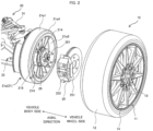
- FIGS. 1 to 4 only one wheel is shown.
- an in-wheel motor on at least one vehicle wheel.
- the vehicle wheel 10 includes a wheel 11 and a tire 12 mounted to the outer periphery of the wheel 11.
- the wheel 11 includes a plurality of spokes 13 radially extending radially outward from a central portion, and a rim 14 joined to the spokes 13.
- the tire 12 is mounted to the outer periphery of the rim 14.
- the spokes 13 are disposed offset so as to be located outside the vehicle with respect to the width direction of the rim 14.
- the in-wheel motor 20 of the present embodiment refers to a driving means of a vehicle wheel housed in the wheel 11.
- the in-wheel motor 20 includes an inner rotor type and an outer rotor type, and further includes one including a reduction gear and one not including a reduction gear, and can be roughly classified into four types.
- an inner rotor type including no reduction gear (direct drive) will be described as an example, but an outer rotor type may be used.
- the hub bearing 26 is fixed to a hub bearing mounting portion 216 formed in a central portion of the stator housing 21a.
- the hub bearing 26 includes a plurality of (five in the present embodiment) hub bolts 261.
- the hub bolt 261 penetrates the brake disc 251.
- the vehicle wheel 10 is fixed to the hub bearing 26 by inserting the hub bolt 261 into a through hole of the wheel 11 and screwing a nut 262 ( FIG. 8 ) .
- stator 21 (the stator housing 21a and the stator housing cover 21b) and the rotor 22 disposed inside the stator 21 constitute a motor that drives the wheel 11 (vehicle wheel 10).
- the inverter device 24 supplies power to the motor.
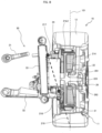
- the stator housing 21a includes a cylindrical housing annular portion 21a1 extending in the axial direction, a housing flat plate portion 21a2 extending in the radial direction orthogonal to the axial direction, a folded portion 21a3 extending in the axial direction and having one end connected to the housing flat plate portion 21a2, and a flange portion 21a4 extending in the radial direction orthogonal to the axial direction and having one end connected to the other end of the folded portion 21a3 and having the other end connected to the housing annular portion 21a1.
- the housing cover flat plate portion 21b2 is formed to be positioned on the opposite open portion side (the vehicle wheel side in the present embodiment) from the position of the housing cover flange portion 21b4 in a state where the stator housing cover 21b closes the open side of the stator housing 21a.
- the housing cover flat plate portion 21b2 is disposed to be recessed from the position of the housing cover flange portion 21b4 toward the opposite open portion side (the vehicle wheel side in the present embodiment).
- a housing cover recess 215 recessed from the position of the housing cover flange portion 21b4 (end portion on the open portion side) toward the opposite open portion side is formed, and a rib 21b3 is disposed in the housing cover recess 215.
- the brake device 25 operates in the same direction as the axial direction of the rotation shaft 223 of the motor.
- a brake device for a vehicle which drives vehicle wheels by a motor is mainly an electric brake such as a regenerative brake or a waste electric brake, but it is also necessary to provide a mechanical brake in preparation for an electric brake failure at the time of sudden braking or full charge.
- the mechanical brake include a drum brake and a disc brake.
- a disc brake is used as a mechanical brake in the present embodiment.
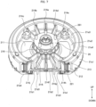
- the housing recess 211 of the stator housing 21a is provided with a plurality of ribs 214 (reinforcing members) connecting the folded portion 21a3 and the hub bearing mounting portion 216.
- the plurality of ribs 214 are radially disposed vertically from the hub bearing mounting portion 216.
- a rib 214a is disposed at a position in the vertical direction (90 degrees) from the horizontal position.
- a rib 214b is disposed in a direction opening from the rib 214a by 20 degrees, that is, at a position 110 degrees from the horizontal position.
- a rib 214c is disposed in a direction opening from the rib 214a by 40 degrees, that is, at a position 130 degrees from the horizontal position.
- a rib 214d is disposed in a direction closing 20 degrees from the rib 214a, that is, at a position 70 degrees from the horizontal position.
- a rib 214e is disposed in a direction closing 40 degrees from the rib 214a, that is, at a position 50 degrees from the horizontal position.
- FIG. 8 is a cross-sectional view taken along line VIII-VIII of FIG. 4 .
Landscapes
- Engineering & Computer Science (AREA)
- Power Engineering (AREA)
- Chemical & Material Sciences (AREA)
- Combustion & Propulsion (AREA)
- Transportation (AREA)
- Mechanical Engineering (AREA)
- Microelectronics & Electronic Packaging (AREA)
- Arrangement Or Mounting Of Propulsion Units For Vehicles (AREA)
Applications Claiming Priority (2)
| Application Number | Priority Date | Filing Date | Title |
|---|---|---|---|
| JP2021140876A JP7557443B2 (ja) | 2021-08-31 | 2021-08-31 | インホイールモータ |
| PCT/JP2022/026017 WO2023032447A1 (fr) | 2021-08-31 | 2022-06-29 | Moteur-roue |
Publications (2)
| Publication Number | Publication Date |
|---|---|
| EP4397518A1 true EP4397518A1 (fr) | 2024-07-10 |
| EP4397518A4 EP4397518A4 (fr) | 2025-07-16 |
Family
ID=85412073
Family Applications (1)
| Application Number | Title | Priority Date | Filing Date |
|---|---|---|---|
| EP22864035.5A Pending EP4397518A4 (fr) | 2021-08-31 | 2022-06-29 | Moteur-roue |
Country Status (5)
| Country | Link |
|---|---|
| US (1) | US12533944B2 (fr) |
| EP (1) | EP4397518A4 (fr) |
| JP (1) | JP7557443B2 (fr) |
| CN (1) | CN117769499A (fr) |
| WO (1) | WO2023032447A1 (fr) |
Families Citing this family (3)
| Publication number | Priority date | Publication date | Assignee | Title |
|---|---|---|---|---|
| JP7583691B2 (ja) * | 2021-08-31 | 2024-11-14 | 株式会社日立製作所 | インホイールモータ |
| IT202200008270A1 (it) * | 2022-04-27 | 2023-10-27 | Ferrari Spa | Dispositivo ruota con motore elettrico integrato per un autoveicolo |
| JP2025054155A (ja) | 2023-09-25 | 2025-04-07 | ジーケーエヌ オートモーティブ リミテッド | インホイールモータ |
Family Cites Families (12)
| Publication number | Priority date | Publication date | Assignee | Title |
|---|---|---|---|---|
| US6566779B2 (en) | 2000-06-02 | 2003-05-20 | Kabushiki Kaisha Moric | Coil winding for DC machine |
| JP4437375B2 (ja) | 2000-06-02 | 2010-03-24 | ヤマハモーターエレクトロニクス株式会社 | ブラシレスdcモータ |
| JP3638586B2 (ja) | 2001-04-16 | 2005-04-13 | 株式会社ブリヂストン | インホイールモータの取付方法及びインホイールモータシステム |
| DE102011081120A1 (de) | 2011-07-07 | 2013-01-10 | Schaeffler Technologies AG & Co. KG | Abgedichtetes Antriebssystem |
| CN102673380B (zh) | 2012-01-18 | 2014-12-31 | 华南理工大学 | 一种内置悬置集成式轮毂电机驱动电动轮 |
| JP6136903B2 (ja) | 2013-12-06 | 2017-05-31 | トヨタ自動車株式会社 | 車輪駆動装置 |
| WO2016170807A1 (fr) | 2015-04-20 | 2016-10-27 | 株式会社Fomm | Structure de suspension de véhicule |
| CN105270161B (zh) | 2015-10-28 | 2018-10-02 | 湖北航天技术研究院特种车辆技术中心 | 一种轮边电机驱动装置 |
| CN107487175B (zh) | 2017-07-25 | 2019-12-31 | 东风汽车公司 | 一种一体化集成式轮毂电机驱动单元 |
| CN107599824B (zh) * | 2017-08-15 | 2019-07-26 | 湖北航天技术研究院特种车辆技术中心 | 一种低速大扭矩单级减速器电动轮 |
| CN209505431U (zh) | 2018-12-18 | 2019-10-18 | 深圳市大富科技股份有限公司 | 一种轮毂电机、车轮及车辆 |
| CN111030350B (zh) | 2019-12-30 | 2020-12-25 | 东风汽车集团有限公司 | 一种集成中央充放气的电动轮毂 |
-
2021
- 2021-08-31 JP JP2021140876A patent/JP7557443B2/ja active Active
-
2022
- 2022-06-29 EP EP22864035.5A patent/EP4397518A4/fr active Pending
- 2022-06-29 WO PCT/JP2022/026017 patent/WO2023032447A1/fr not_active Ceased
- 2022-06-29 CN CN202280052531.8A patent/CN117769499A/zh active Pending
- 2022-06-29 US US18/580,134 patent/US12533944B2/en active Active
Also Published As
| Publication number | Publication date |
|---|---|
| WO2023032447A1 (fr) | 2023-03-09 |
| CN117769499A (zh) | 2024-03-26 |
| US20250033459A1 (en) | 2025-01-30 |
| US12533944B2 (en) | 2026-01-27 |
| JP7557443B2 (ja) | 2024-09-27 |
| JP2023034574A (ja) | 2023-03-13 |
| EP4397518A4 (fr) | 2025-07-16 |
Similar Documents
| Publication | Publication Date | Title |
|---|---|---|
| EP4397518A1 (fr) | Moteur-roue | |
| US7528518B2 (en) | In-wheel motor | |
| KR101004598B1 (ko) | 인휠 모터 장착용 휠 구조체 | |
| KR102708798B1 (ko) | 인휠 구동장치 | |
| EP2543531B1 (fr) | Dispositif entraîné par un moteur-roue | |
| US9340103B2 (en) | In-wheel motor drive device | |
| CN104691304B (zh) | 轮毂总成及具备上述轮毂总成的车辆 | |
| JP5704043B2 (ja) | 車輪制駆動装置 | |
| KR101841009B1 (ko) | 인휠 구동장치 | |
| JP5461580B2 (ja) | 電動モータホイール構造体 | |
| WO2011058844A1 (fr) | Dispositif d'entraînement de moteur-roue | |
| KR20140081351A (ko) | 인휠 모터 어셈블리 | |
| US20220048317A1 (en) | Braking structure for in-wheel motor drive device | |
| JP5292626B2 (ja) | インホイールモータ駆動装置およびインホイールモータ駆動装置用ケーシング | |
| JP4730078B2 (ja) | インホイールモータ | |
| JP5374326B2 (ja) | インホイールモータ駆動装置 | |
| JP2013147177A (ja) | 駆動装置、及びインホイールモータ駆動装置 | |
| JP2008273406A (ja) | 車輪駆動装置 | |
| EP4397519A1 (fr) | Moteur-roue | |
| JP5736069B2 (ja) | インホイールモータ駆動装置 | |
| KR102466954B1 (ko) | 인휠 모터 장착형 휠 어셈블리 | |
| CN112912265A (zh) | 轮毂电动机驱动装置与制动钳的结合结构 | |
| JP5523860B2 (ja) | インホイールモータ駆動装置 | |
| JP2014206193A (ja) | 駆動ユニット | |
| JP2006117124A (ja) | 車輪構造 |
Legal Events
| Date | Code | Title | Description |
|---|---|---|---|
| STAA | Information on the status of an ep patent application or granted ep patent |
Free format text: STATUS: THE INTERNATIONAL PUBLICATION HAS BEEN MADE |
|
| PUAI | Public reference made under article 153(3) epc to a published international application that has entered the european phase |
Free format text: ORIGINAL CODE: 0009012 |
|
| STAA | Information on the status of an ep patent application or granted ep patent |
Free format text: STATUS: REQUEST FOR EXAMINATION WAS MADE |
|
| 17P | Request for examination filed |
Effective date: 20240331 |
|
| AK | Designated contracting states |
Kind code of ref document: A1 Designated state(s): AL AT BE BG CH CY CZ DE DK EE ES FI FR GB GR HR HU IE IS IT LI LT LU LV MC MK MT NL NO PL PT RO RS SE SI SK SM TR |
|
| DAV | Request for validation of the european patent (deleted) | ||
| DAX | Request for extension of the european patent (deleted) | ||
| A4 | Supplementary search report drawn up and despatched |
Effective date: 20250616 |
|
| RIC1 | Information provided on ipc code assigned before grant |
Ipc: B60K 7/00 20060101AFI20250610BHEP |
|
| STAA | Information on the status of an ep patent application or granted ep patent |
Free format text: STATUS: EXAMINATION IS IN PROGRESS |
|
| 17Q | First examination report despatched |
Effective date: 20260108 |