EP4397564A1 - Système de détection d'objet et procédé de détection d'objet - Google Patents
Système de détection d'objet et procédé de détection d'objet Download PDFInfo
- Publication number
- EP4397564A1 EP4397564A1 EP22863934.0A EP22863934A EP4397564A1 EP 4397564 A1 EP4397564 A1 EP 4397564A1 EP 22863934 A EP22863934 A EP 22863934A EP 4397564 A1 EP4397564 A1 EP 4397564A1
- Authority
- EP
- European Patent Office
- Prior art keywords
- region
- interest
- roi
- track
- image
- Prior art date
- Legal status (The legal status is an assumption and is not a legal conclusion. Google has not performed a legal analysis and makes no representation as to the accuracy of the status listed.)
- Pending
Links
Images





Classifications
-
- G—PHYSICS
- G06—COMPUTING OR CALCULATING; COUNTING
- G06T—IMAGE DATA PROCESSING OR GENERATION, IN GENERAL
- G06T7/00—Image analysis
-
- B—PERFORMING OPERATIONS; TRANSPORTING
- B61—RAILWAYS
- B61L—GUIDING RAILWAY TRAFFIC; ENSURING THE SAFETY OF RAILWAY TRAFFIC
- B61L23/00—Control, warning or like safety means along the route or between vehicles or trains
- B61L23/04—Control, warning or like safety means along the route or between vehicles or trains for monitoring the mechanical state of the route
- B61L23/041—Obstacle detection
-
- G—PHYSICS
- G06—COMPUTING OR CALCULATING; COUNTING
- G06T—IMAGE DATA PROCESSING OR GENERATION, IN GENERAL
- G06T7/00—Image analysis
- G06T7/60—Analysis of geometric attributes
-
- G—PHYSICS
- G06—COMPUTING OR CALCULATING; COUNTING
- G06V—IMAGE OR VIDEO RECOGNITION OR UNDERSTANDING
- G06V10/00—Arrangements for image or video recognition or understanding
- G06V10/20—Image preprocessing
- G06V10/25—Determination of region of interest [ROI] or a volume of interest [VOI]
-
- G—PHYSICS
- G06—COMPUTING OR CALCULATING; COUNTING
- G06V—IMAGE OR VIDEO RECOGNITION OR UNDERSTANDING
- G06V10/00—Arrangements for image or video recognition or understanding
- G06V10/40—Extraction of image or video features
- G06V10/62—Extraction of image or video features relating to a temporal dimension, e.g. time-based feature extraction; Pattern tracking
-
- G—PHYSICS
- G06—COMPUTING OR CALCULATING; COUNTING
- G06V—IMAGE OR VIDEO RECOGNITION OR UNDERSTANDING
- G06V20/00—Scenes; Scene-specific elements
- G06V20/50—Context or environment of the image
- G06V20/52—Surveillance or monitoring of activities, e.g. for recognising suspicious objects
- G06V20/54—Surveillance or monitoring of activities, e.g. for recognising suspicious objects of traffic, e.g. cars on the road, trains or boats
-
- G—PHYSICS
- G06—COMPUTING OR CALCULATING; COUNTING
- G06V—IMAGE OR VIDEO RECOGNITION OR UNDERSTANDING
- G06V20/00—Scenes; Scene-specific elements
- G06V20/50—Context or environment of the image
- G06V20/56—Context or environment of the image exterior to a vehicle by using sensors mounted on the vehicle
- G06V20/58—Recognition of moving objects or obstacles, e.g. vehicles or pedestrians; Recognition of traffic objects, e.g. traffic signs, traffic lights or roads
Definitions
- the present invention relates to a technology of detecting a target object in an image.
- motorman-less operation has already been realized in subway systems or new types of transportation that cause railway vehicles to travel on elevated railroads, there are no practical examples of routes where humans may enter, such as routes where there are level crossings and the like or routes in rail yards where there are workers.
- Realization of motorman-less operation requires means for detecting obstacles such as humans or vehicles that may enter tracks. Particularly, it is necessary to detect distant obstacles fast and highly precisely in order to decelerate or stop upon detection of obstacles.
- cameras and image processing are used to perform obstacle detection.
- technologies to recognize and detect objects by image processing there are general object recognition technologies with precision which has been enhanced rapidly owing to deep learning in recent years.
- the general object recognition technologies have a tendency that the precision of detecting objects with smaller pixel counts in images deteriorates.
- ROIs are limited by defining a region that needs to be monitored, in a case where the region is large or in a case where there are a plurality of regions and the regions are distributed over a wide range in an image, the image needs to be captured with a large angle of view; as a result, a captured image of a target object becomes small undesirably, and the sensing may fail.
- An object detection system detects objects in an image captured from a moving body moving on a track with a specified width.
- the system can be used for detection of obstacles of a railway vehicle travelling on a track including rails, a conveyance robot moving on a track which is a lane with a predetermined width, and the like.
- the system can be used for operation assistance, automated operation, and the like of moving bodies travelling on tracks.
- a specific explanation is given with regard to an example of a system that detects obstacles of a railway vehicle moving on rails.
- the structure gauge determines dimensional bounds defining a region around the track on which the railway vehicle is travelling and the construction of buildings, the planting of trees, or the like are prohibited in the region.
- the structure gauge is a region with a certain width L [m] centered on the center of the track on which the railway vehicle is moving. That is, both sides of the track are detection targets.
- the numerical value of the width L is predetermined for a certain track width R [m].
- the obstacle detection system sets ROIs on the basis of detection conditions required for detecting an obstacle appropriately. As a result, ROIs that enable appropriate balance of detection precision, a range of detection, a processing speed, and the like can be set.
- the track width and the structure gauge width are constant widths.
- v coordinates (ordinates) in the longitudinal direction and u coordinates (abscissas) in the lateral direction are set, with their origins at the upper left corner of an image. It can be considered that the ratios (scales) between lengths in the real world and lengths in the image do not change if v coordinates in the image of measured geographical points are the same.
- the obstacle detection system determines ROIs on the basis of a track width in an image and a predetermined coefficient. This coefficient is called an ROI coefficient.
- the ROI coefficient is based on a pixel count of a target object in an image necessary for detection, the size of the detection-target object in the real world, the input image size of an object recognition program, and a track width in the real world.
- the width of an ROI is determined as the track width R [m] multiplied by the coefficient.
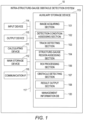
- the intra-structure-gauge obstacle detection system 10 further includes a communication interface (IF) 116 that performs data communication with external devices such as another computer device, an external storage device, a camera, a microphone, or various types of sensors and an auxiliary storage device 113 that provides a non-volatile storage area using an HDD (Hard Disk Drive), a flash memory, or the like.
- IF communication interface
- the image acquiring section 101 receives an image from a monitoring camera received via the communication interface 116.
- the input image is an image including an image of a track which is a captured image of the space in an advancing direction of a railway vehicle.
- FIG. 2 schematically depicts an example of the input image.
- An input image 20 includes a track 25 extending forward from a railway vehicle.
- the track 25 extends between trees around it.
- the track 25 includes a left rail 26 and a right rail 27, and these define the width of the track 25.
- v coordinates in the longitudinal direction and u coordinates in the lateral direction are set, with their origins at the upper left corner of the input image 20.
- the ROI processing section 106 determines a plurality of ROIs, and outputs them.
- the obstacle detecting section 107 performs an obstacle detection process by using, as input, an image included in each ROI.
- the result output section 108 outputs obstacle detection results obtained by the detection by the obstacle detecting section 107.
- the intra-structure-gauge obstacle detection system 10 may be a physical computer system (one or more physical computers) or may be a system built on a group of computational resources (a plurality of computational resources) such as a cloud computing infrastructure.
- the intra-structure-gauge obstacle detection system 10 may be mobile equipment such as a smartphone or a tablet.
- the computer system or the group of computational resources includes one or more interface devices, one or more storage devices (e.g., including a main storage device and an auxiliary storage device), and one or more calculating devices.
- the programs may be installed from a program source.
- the program source may be a program distribution computer or a computer-readable storage medium (e.g., a computer-readable non-transitory storage medium).
- a program distribution computer or a computer-readable storage medium (e.g., a computer-readable non-transitory storage medium).
- a computer-readable storage medium e.g., a computer-readable non-transitory storage medium.
- FIG. 3 is a block diagram schematically depicting the configuration of the ROI processing section 106.
- An image input section 301 receives, as input, the image captured by the monitoring camera and acquired by the image acquiring section 101.
- a track detection result input section 302 receives, as input, the coordinates of the left and right rails of the track detected by the track detecting section 103.
- a detection condition input section 303 receives, as input, the detection conditions from the detection condition assessing section 102.
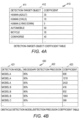
- FIG. 4D depicts a configuration example of a weather/time interval coefficient table 440.
- the weather/time interval coefficient table 440 manages the relation between weather/time intervals at the times of obstacle detection and coefficients.
- the weather/time interval coefficient table 440 includes a weather field 441, a time interval field 442, and a coefficient field 443.
- the weather field 441 represents weather such as fine weather or rain
- the time interval field 442 represents time intervals such as daytime or nighttime. Note that the weather field or the time interval field may represent weather or time intervals by another method.
- the coefficient field 423 represents coefficients for combinations of weather and time intervals.
- step 506 the obstacle detecting section 107 performs an obstacle detection process on all the ROIs.
- the procedure proceeds to step 508.
- the result output section 108 issues an obstacle detection alert.
- the result output section 108 may give a warning to the motorman, or in a case where the result output section 108 is connected with an operation control device of the railway vehicle, the result output section 108 may perform a process of decelerating the vehicle.
- the ROI determining section 306 determines a width r k of an ROI k which is the k-th ROI, by multiplying a width w k of the track at a geographical point at a v coordinate v k in a screen by the ROI coefficient.
- the ROI is a square.
- the v coordinate of the upper side of the ROI k is v k .
- v k is the reference ordinate value of the ROI k .
- a track 210 extends forward from the near side. That is, the track 210 extends from the lower side to the upper side of the input image.
- u coordinates increase from the left side to the right side
- v coordinates increase from the upper side to the lower side.
- the v coordinate of a geographical point where the ROI k starts being unable to cover the structure-gauge region is the v coordinate of the lower side of the ROI k .
- the v coordinate of the geographical point where the ROI k starts being unable to cover the structure-gauge region is a v coordinate v k+1 of the upper side of the following ROI k+1 .
- the track 210 On the upper side of the ROI k+1 , that is, at the v coordinate v k+1 , the track 210 has a width w k+1 , and the structure-gauge region has a width l k+1 .
- the ROI k+1 has a width r k+1 .
- the relation of l k+1 (L/R)w k+1 holds true.
- abscissa values of the ROI k there are abscissa values of the ROI k at which both the lower intersections of the two structure-gauge lines and the ROI k are positioned on the lower side of the ROI k .
- the abscissa values can be set as abscissa values of the ROI k for performing the target-object detection process.
- the v coordinate of the geographical point where the ROI k starts being unable to cover the structure-gauge region is the v coordinate v k+1 of the upper side of the following ROI k+1 . That is, the v coordinate v k+1 of the upper side of the following ROI k+1 coincides with the v coordinates of the lower intersections.
- the intersection C k+1 of the upper side of the ROI k+1 and the centerline of the track 210 has the coordinates (u k+1 , v k+1 ).
- the intersection C k+1 of the upper side of the ROI k+1 and the centerline of the track 210 has the coordinates (u k+1 , v k+1 ).
- the track 210 On the upper side of the ROI k+1 , that is, at the v coordinate v k+1 , the track 210 has the width w k+1 , and the structure-gauge region has the width l k+1 .
- the ROI k+1 has the width r k+1 .
- the fourth pattern is a case where the ROI k reaches the lower end of the screen, and an ROI 1 to the ROI k cover the entire structure-gauge region in the input image.
- the v coordinate v k where the width of the track is measured is used as the v coordinate value of the upper end of the ROI k .
- the v coordinate v k is the reference ordinate value of the ROI k .
- the v coordinate value of the upper end of the ROI k may be different from v k , for example, may be positioned higher than v k .
- the u coordinate of the center of the ROI k is determined such that the v coordinates of the intersections of the two structure-gauge lines and the left and right sides of the ROI k become the same.
- the u coordinate of the center of the ROI k and the u coordinate of the center of the track at the v coordinate v k+1 match.
- the ROI k can include the entire region of the structure-gauge region from the v coordinate v k to the v coordinate v k+1 .
- the ROI k in FIG. 8 satisfies this condition.
- the ROI determining section 306 may determine, as the u coordinate of the center of the ROI k , (u k +l k /2-r k /2 (when u k > u k+1 )) or (u k -l k /2+r k /2 (when u k ⁇ u k+1 )).
- the ROI k can include the entire region of the structure-gauge region from the v coordinate v k to the v coordinate v k+1 .
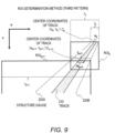
- One of the structure-gauge lines crosses the upper corner of the ROI k .
- the ROI k in FIG. 9 satisfies this condition.
- the ROI determining section 306 determines, as the u coordinate of the center of the ROI k , the u coordinate of the center of the track at the v coordinate v k .
- the ROI k can include the entire region of the structure-gauge region in the image.
- the u coordinate value of the ROI k in each pattern may be determined by a method that is different from the methods described above.
- the u coordinate of the center of the track at the v coordinate v k may be determined as the u coordinate of the center of the ROI k .
- step 611 the ROI determining section 306 increments k. Thereafter, the procedure returns to step 606, and the next ROI is determined at a new position of the v coordinate v k .
- one or more ROIs cover the structure-gauge region in an input image over the range from the far side to the near side.
- target objects can be detected in each ROI with the necessary detection precision set in the detection conditions.
- FIG. 10 depicts an example of a plurality of ROIs formed for one input image.
- three ROIs are formed for the input image 20, and the three ROIs covers the entire structure-gauge region in the input image 20.
- the three ROIs are the ROI 1 , the ROI 2 , and the ROI 3 .
- the ROI 1 and the ROI 2 are ROIs of the second pattern explained with reference to FIG. 8
- the ROI 3 is an ROI of the fourth pattern.
- Each ROI represents a detection limit of a region within which target objects can be detected.
- the ROI determining section 306 determines the v coordinate v 1 of the ROI 1 , which is the first ROI, and the ROI coefficient. From the ROI coefficient and the track width at the v coordinate v 1 , the length of one side of the ROI 1 is determined. On the upper side of the ROI 1 , that is, at the v coordinate v 1 , the track 210 has a width w 1 , and the structure-gauge region has a width l 1 . The ROI 1 has a width r 1 .
- the ROI determining section 306 adjusts the u coordinate of the ROI 1 as necessary, and assesses the relation between the ROI 1 and the structure gauge.
- the relation between the ROI 1 and the track 210 corresponds to the second pattern.
- the left structure-gauge line 220A of the track 210 crosses the upper side and the left side of the ROI 1 .
- the right structure-gauge line 220B of the track 210 crosses the upper side and the right side of the ROI 1 .
- the ROI determining section 306 performs a process of forming the next ROI 2 at the v coordinate v 2 .
- the formation of the ROI 2 is similar to the formation of the ROI 1 described above.
- the track 210 On the upper side of the ROI 2 , that is, at the v coordinate v 2 , the track 210 has a width w 2 , and the structure-gauge region has a width l 2 .
- the ROI 2 has a width r 2 .
- the structure-gauge lines 220A and 220B cross the left and right sides of the ROI 2 at a v coordinate v 3 .
- the ROI 3 is formed at the v coordinate v 3 .
- the track 210 has a width w 3
- the structure-gauge region has a width l 3 .
- the ROI 3 has a width r 3 .
- the relation between the ROI 3 and the structure-gauge region corresponds to the fourth pattern.
- the u coordinate of the center of the ROI 3 is determined in such a manner as to coincide with the u coordinate of the center of the track 210 at the v coordinate v 3 .
- the present invention is not limited to the embodiments described above, and includes various modification examples.
- the embodiments described above are explained in detail for explaining the present invention in an easy-to-understand manner, and the present invention is not necessarily limited to those including all constituent elements explained..
- some of constituent elements of each embodiment can also have other constituent elements additionally, be removed, or be replaced.
- each constituent element, function, processing section, or the like described above may.be partially or entirely realized by hardware by, for example, designing it with an integrated circuit.
- each constituent element, function, and the like described above may be realized by software by a processor interpreting and executing a program to realize each function.
- Information such as a program, a table or a file to realize each function can be placed on a recording device such as a memory, a hard disk, or an SSD (Solid State Drive) or a recording medium such as an IC card or an SD card.
- control lines and information lines are ones that are considered to be necessary for explanation, and all control lines and information lines that are necessary for products are not necessarily depicted. It may be considered that, in practice, almost all constituent elements are interconnected.
Landscapes
- Engineering & Computer Science (AREA)
- Physics & Mathematics (AREA)
- General Physics & Mathematics (AREA)
- Theoretical Computer Science (AREA)
- Multimedia (AREA)
- Computer Vision & Pattern Recognition (AREA)
- Mechanical Engineering (AREA)
- Geometry (AREA)
- Image Analysis (AREA)
- Train Traffic Observation, Control, And Security (AREA)
- Image Processing (AREA)
Applications Claiming Priority (2)
| Application Number | Priority Date | Filing Date | Title |
|---|---|---|---|
| JP2021141404A JP7734534B2 (ja) | 2021-08-31 | 2021-08-31 | 対象物を検出するシステム及び対象物を検出する方法 |
| PCT/JP2022/017760 WO2023032344A1 (fr) | 2021-08-31 | 2022-04-14 | Système de détection d'objet et procédé de détection d'objet |
Publications (2)
| Publication Number | Publication Date |
|---|---|
| EP4397564A1 true EP4397564A1 (fr) | 2024-07-10 |
| EP4397564A4 EP4397564A4 (fr) | 2025-07-02 |
Family
ID=85412071
Family Applications (1)
| Application Number | Title | Priority Date | Filing Date |
|---|---|---|---|
| EP22863934.0A Pending EP4397564A4 (fr) | 2021-08-31 | 2022-04-14 | Système de détection d'objet et procédé de détection d'objet |
Country Status (3)
| Country | Link |
|---|---|
| EP (1) | EP4397564A4 (fr) |
| JP (1) | JP7734534B2 (fr) |
| WO (1) | WO2023032344A1 (fr) |
Families Citing this family (2)
| Publication number | Priority date | Publication date | Assignee | Title |
|---|---|---|---|---|
| JP2026002633A (ja) * | 2024-06-21 | 2026-01-08 | 株式会社日立製作所 | 障害物検知システム |
| KR102842712B1 (ko) * | 2024-11-08 | 2025-08-06 | 한국철도기술연구원 | 영상 기반의 실시간 선로 검출 방법 |
Family Cites Families (7)
| Publication number | Priority date | Publication date | Assignee | Title |
|---|---|---|---|---|
| JP6381981B2 (ja) * | 2014-06-12 | 2018-08-29 | 西日本旅客鉄道株式会社 | 線路空間支障物検知システム |
| US11021177B2 (en) * | 2016-10-20 | 2021-06-01 | Rail Vision Ltd | System and method for object and obstacle detection and classification in collision avoidance of railway applications |
| JP7000232B2 (ja) | 2018-04-02 | 2022-02-04 | 株式会社東芝 | 前方監視装置、支障物衝突回避装置及び列車制御装置 |
| EP3787953B1 (fr) * | 2018-05-01 | 2025-07-30 | Rail Vision Ltd | Système et procédé de sélection dynamique de fréquence d'échantillonnage élevée pour une région d'intérêt sélectionnée |
| JP7217094B2 (ja) * | 2018-05-30 | 2023-02-02 | 日本信号株式会社 | 監視装置 |
| JP7316107B2 (ja) * | 2019-06-19 | 2023-07-27 | 日本信号株式会社 | 監視装置 |
| JP6714942B1 (ja) | 2020-03-04 | 2020-07-01 | フォクレット合同会社 | コミュニケーションシステム、コンピュータプログラム、及び情報処理方法 |
-
2021
- 2021-08-31 JP JP2021141404A patent/JP7734534B2/ja active Active
-
2022
- 2022-04-14 EP EP22863934.0A patent/EP4397564A4/fr active Pending
- 2022-04-14 WO PCT/JP2022/017760 patent/WO2023032344A1/fr not_active Ceased
Also Published As
| Publication number | Publication date |
|---|---|
| JP2023034917A (ja) | 2023-03-13 |
| EP4397564A4 (fr) | 2025-07-02 |
| WO2023032344A1 (fr) | 2023-03-09 |
| JP7734534B2 (ja) | 2025-09-05 |
Similar Documents
| Publication | Publication Date | Title |
|---|---|---|
| CN109087510B (zh) | 交通监测方法及装置 | |
| EP3063552B1 (fr) | Method et systeme pour l'estimation d'une largeur de route | |
| JP4409035B2 (ja) | 画像処理装置、特異箇所検出方法、及び特異箇所検出プログラムを記録した記録媒体 | |
| CN110286389B (zh) | 一种用于障碍物识别的栅格管理方法 | |
| JP6850324B2 (ja) | マルチモデルに基づく障害物分布シミュレーション方法、装置、端末及びプログラム | |
| CN109871787B (zh) | 一种障碍物检测方法及装置 | |
| CN111295321A (zh) | 障碍物检测装置 | |
| EP4397564A1 (fr) | Système de détection d'objet et procédé de détection d'objet | |
| CN110349260B (zh) | 一种路面标线自动提取方法及装置 | |
| CN113424240B (zh) | 行驶道路识别装置 | |
| CN102208013A (zh) | 风景匹配参考数据生成系统和位置测量系统 | |
| DE102011117585A1 (de) | Systeme und Verfahren zum Verfolgen von Objekten | |
| US10748014B2 (en) | Processing device, object recognition apparatus, device control system, processing method, and computer-readable recording medium | |
| CN112912894B (zh) | 道路边界识别方法和装置 | |
| CN112818792A (zh) | 车道线检测方法、装置、电子设备及计算机存储介质 | |
| US12243321B2 (en) | Method for determining a semantic free space | |
| DE112018004835T5 (de) | Kollisionsvorhersagevorrichtung, Kollisionsvorhersageverfahren und Programm | |
| WO2021000787A1 (fr) | Procédé et dispositif de reconnaissance de géométrie de route | |
| CN113536867B (zh) | 物体识别的方法、装置及系统 | |
| CN114387293A (zh) | 道路边缘检测方法、装置、电子设备及车辆 | |
| CN119291717A (zh) | 铁路轨道障碍物检测方法及系统 | |
| CN114998855A (zh) | 道路边缘线的生成方法、装置、存储介质和计算机设备 | |
| CN111583257B (zh) | 铁路限界异物侵入检测方法、装置及系统 | |
| KR20200058272A (ko) | 도로 주행 영상의 전처리를 통한 도로 주행 상황 제공 방법 및 시스템 | |
| CN112561967A (zh) | 一种车辆门锁的控制方法及装置 |
Legal Events
| Date | Code | Title | Description |
|---|---|---|---|
| STAA | Information on the status of an ep patent application or granted ep patent |
Free format text: STATUS: THE INTERNATIONAL PUBLICATION HAS BEEN MADE |
|
| PUAI | Public reference made under article 153(3) epc to a published international application that has entered the european phase |
Free format text: ORIGINAL CODE: 0009012 |
|
| STAA | Information on the status of an ep patent application or granted ep patent |
Free format text: STATUS: REQUEST FOR EXAMINATION WAS MADE |
|
| 17P | Request for examination filed |
Effective date: 20240331 |
|
| AK | Designated contracting states |
Kind code of ref document: A1 Designated state(s): AL AT BE BG CH CY CZ DE DK EE ES FI FR GB GR HR HU IE IS IT LI LT LU LV MC MK MT NL NO PL PT RO RS SE SI SK SM TR |
|
| DAV | Request for validation of the european patent (deleted) | ||
| DAX | Request for extension of the european patent (deleted) | ||
| A4 | Supplementary search report drawn up and despatched |
Effective date: 20250602 |
|
| RIC1 | Information provided on ipc code assigned before grant |
Ipc: G06T 7/60 20170101ALI20250526BHEP Ipc: G06T 7/00 20170101ALI20250526BHEP Ipc: B61L 23/00 20060101AFI20250526BHEP |
|
| GRAP | Despatch of communication of intention to grant a patent |
Free format text: ORIGINAL CODE: EPIDOSNIGR1 |
|
| STAA | Information on the status of an ep patent application or granted ep patent |
Free format text: STATUS: GRANT OF PATENT IS INTENDED |
|
| INTG | Intention to grant announced |
Effective date: 20251121 |
|
| GRAS | Grant fee paid |
Free format text: ORIGINAL CODE: EPIDOSNIGR3 |