EP4397579A1 - Aerodynamische luftspaltabdichtungsvorrichtung für ein kraftfahrzeug und kraftfahrzeug, insbesondere lastkraftwagen, mit solch einer vorrichtung - Google Patents
Aerodynamische luftspaltabdichtungsvorrichtung für ein kraftfahrzeug und kraftfahrzeug, insbesondere lastkraftwagen, mit solch einer vorrichtung Download PDFInfo
- Publication number
- EP4397579A1 EP4397579A1 EP23150345.9A EP23150345A EP4397579A1 EP 4397579 A1 EP4397579 A1 EP 4397579A1 EP 23150345 A EP23150345 A EP 23150345A EP 4397579 A1 EP4397579 A1 EP 4397579A1
- Authority
- EP
- European Patent Office
- Prior art keywords
- truck
- motorized vehicle
- air
- gap
- sealing
- Prior art date
- Legal status (The legal status is an assumption and is not a legal conclusion. Google has not performed a legal analysis and makes no representation as to the accuracy of the status listed.)
- Pending
Links
Images


Classifications
-
- B—PERFORMING OPERATIONS; TRANSPORTING
- B62—LAND VEHICLES FOR TRAVELLING OTHERWISE THAN ON RAILS
- B62D—MOTOR VEHICLES; TRAILERS
- B62D35/00—Vehicle bodies characterised by streamlining
- B62D35/001—For commercial vehicles or tractor-trailer combinations, e.g. caravans
-
- B—PERFORMING OPERATIONS; TRANSPORTING
- B60—VEHICLES IN GENERAL
- B60R—VEHICLES, VEHICLE FITTINGS, OR VEHICLE PARTS, NOT OTHERWISE PROVIDED FOR
- B60R3/00—Arrangements of steps or ladders facilitating access to or on the vehicle, e.g. running-boards
- B60R3/002—Running boards
-
- B—PERFORMING OPERATIONS; TRANSPORTING
- B62—LAND VEHICLES FOR TRAVELLING OTHERWISE THAN ON RAILS
- B62D—MOTOR VEHICLES; TRAILERS
- B62D33/00—Superstructures for load-carrying vehicles
- B62D33/06—Drivers' cabs
- B62D33/0604—Cabs insulated against vibrations or noise, e.g. with elastic suspension
Definitions
- the disclosure relates to an apparatus for aerodynamically sealing at least part of an air gap formed between at least two parts part of a motorized vehicle, and to a motorized vehicle, in particular a truck, comprising such an apparatus.
- Motor vehicles may have, for example on their external body, some parts between which an air gap is formed. These air gaps constitute the entry gate for undesired air seepage, and thus may negatively influence the aerodynamic efficiency of the vehicle. Also the overall aesthetic impression of the vehicle may be negatively impacted by such air gaps, since internal parts may become too visible.
- the or each mechanical connector comprises a plastic rivet having an axially movable plunger.
- the apparatus can be installed according to a simple and not expensive solution.
- the air-gap sealing portion comprises at least one edge part which is suitable to overlap with an associated portion of said second part of the motorized vehicle. Accordingly, at least partial closure of the air gap may be further improved.
- a motorized vehicle comprising at least one apparatus for aerodynamically sealing at least part of an air gap formed between at least two parts of the vehicle itself, as above defined, and in particular as described hereinafter and defined in the relevant appended claims.
- a truck comprising:
- the apparatus can be used for at least partially sealing any air gap formed between two parts of a motorized vehicle, and in particular of a truck.
- the apparatus further comprises a mounting structure which is suitable to be connected to said first part of the motorized vehicle, and wherein said at least one mechanical connector connects the connecting portion of the sealing device (10) to said mounting structure.
- the first part is a substantially fixed part of the truck
- the second part is a part of the truck movable, with respect to the fixed part, between a first position, where the second part is spaced apart from the first fixed part, and a second position, where the second movable part is positioned close to and forms said air gap with said first fixed part.
- the apparatus may be conveniently used to for at least partially sealing the air gap between two parts of a truck having relative large motion.
- the substantially first fixed part of the truck comprises or is constituted by a front panel of the truck
- the second movable part comprises or is constituted by the step of the truck
- the apparatus may be conveniently used to for at least partially sealing the air gap between two parts of a truck having relative large motion, such as between the step and the front panel.
- the or each mechanical connector comprises a plastic rivet having an axially movable plunger.
- the air-gap sealing portion comprises at least two adjacent sections which form a predefined angle ( ⁇ ) between them.
- any component as a whole, or to any part of a component, or to a combination of components, it has to be understood that it means and encompasses correspondingly either the structure, and/or configuration and/or form and/or positioning of the related component or part thereof, or combinations, such term refers to.
- air gaps between parts of motorized vehicles e.g. at the external body thereof, such as the air gaps formed between large parts having relative motion in front parts of trucks, constitute a kind of rat holes through which airflow can penetrate and may generate aerodynamic disturbances.
- air gaps may negatively impact the overall aesthetic appearance of the vehicle since internal parts may become visible.
- undesired penetrating airflow may impact on the cooling efficiency as well.
- the adoption of an apparatus for aerodynamically sealing at least part of such air gaps allows mitigating, if not completely preventing, the negative effects of undesired air seepage.
- the overall aesthetic impression of the vehicle may be improved.
- any negative impact on cooling of the undesired air seepage via such air gaps may be prevented, thus possibly improving cooling efficiency.
- the motorized vehicle can be any suitable motorized vehicle.
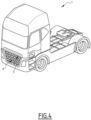
- FIG. 4 there is illustrated a truck 1 in the form of a semi-trailer tractor.
- the truck 1 comprises for example, at its lower front, a front panel 3 which is a substantially fixed part, and a step 4.
- the step 4 is movable relative to the front panel 3 between a first position, illustrated in FIG. 5 , where the step 4 is spaced apart from the front panel 3, and a second position, illustrated in FIG. 4 and in FIG. 6 , where the step 4 is close to and forms an air gap with the front panel 3.
- the apparatus 100 can be used for aerodynamically sealing any air gap 2 formed by at least two adjacent parts of any motorized vehicle, e.g. two parts of the external carbody or frame; depending on the applications, the two parts can be both fixed, both movable, one movable relative to the other, as it happens for the step 4 relative to the front panel 3, there could be even more than two parts, etc.
- the illustrated front panel 3 and the step 4 will be used as an example of any two parts of a motorized vehicle 1 between which an air gap can be formed, such as the illustrated air gap 2.
- connection portion 12 is suitable to be connected to the first part 3 of the motorized vehicle 1, such as the front panel 3 of the truck 1.
- the connecting portion 12 can be connected to the first part 3 directly or indirectly, namely via an additional part connected in its turn to the first part 3.
- the mounting structure is connected to a portion of the front panel 3, with the sealing device 10, in particular its connecting portion 12, by means of at least one mechanical connector 20, preferably by a plurality of mechanical connectors 20, for example three as illustrated in FIG. 2 .
- the mounting structure 30 can be realized in one or more pieces, for example made of any suitable plastics material; further, depending on the applications, and in particular on the type, shape and position of the pieces forming the air gap to be aerodynamically sealed, as well as the space available for mounting the apparatus 100, the body of the mounting structure 30 can be different from the one depicted in the exemplary figures.
- the additional part can be another part of the motorized vehicle connected to the first part 3.
- the shaped body of the sealing device 10 may be realized in one piece.
- the sealing device 10 may be realized of any suitable rubber material.
- Relative terms such as “below” or “above” or “upper” or “lower” or “horizontal” or “vertical” may be used herein to describe a relationship of one element to another element as illustrated in the Figures. It will be understood that these terms and those discussed above are intended to encompass different orientations of the device in addition to the orientation depicted in the Figures. It will be understood that when an element is referred to as being “connected” or “coupled” to another element, it can be directly connected or coupled to the other element, or intervening elements may be present. In contrast, when an element is referred to as being “directly connected” or “directly coupled” to another element, there are no intervening elements present.
Landscapes
- Engineering & Computer Science (AREA)
- Chemical & Material Sciences (AREA)
- Combustion & Propulsion (AREA)
- Transportation (AREA)
- Mechanical Engineering (AREA)
- Seal Device For Vehicle (AREA)
Priority Applications (2)
| Application Number | Priority Date | Filing Date | Title |
|---|---|---|---|
| EP23150345.9A EP4397579A1 (de) | 2023-01-04 | 2023-01-04 | Aerodynamische luftspaltabdichtungsvorrichtung für ein kraftfahrzeug und kraftfahrzeug, insbesondere lastkraftwagen, mit solch einer vorrichtung |
| US18/398,338 US20240217595A1 (en) | 2023-01-04 | 2023-12-28 | Air-gap aerodynamically sealing apparatus for a motorized vehicle, and motorized vehicle, in particular a truck, comprising such an apparatus |
Applications Claiming Priority (1)
| Application Number | Priority Date | Filing Date | Title |
|---|---|---|---|
| EP23150345.9A EP4397579A1 (de) | 2023-01-04 | 2023-01-04 | Aerodynamische luftspaltabdichtungsvorrichtung für ein kraftfahrzeug und kraftfahrzeug, insbesondere lastkraftwagen, mit solch einer vorrichtung |
Publications (1)
| Publication Number | Publication Date |
|---|---|
| EP4397579A1 true EP4397579A1 (de) | 2024-07-10 |
Family
ID=84819813
Family Applications (1)
| Application Number | Title | Priority Date | Filing Date |
|---|---|---|---|
| EP23150345.9A Pending EP4397579A1 (de) | 2023-01-04 | 2023-01-04 | Aerodynamische luftspaltabdichtungsvorrichtung für ein kraftfahrzeug und kraftfahrzeug, insbesondere lastkraftwagen, mit solch einer vorrichtung |
Country Status (2)
| Country | Link |
|---|---|
| US (1) | US20240217595A1 (de) |
| EP (1) | EP4397579A1 (de) |
Citations (6)
| Publication number | Priority date | Publication date | Assignee | Title |
|---|---|---|---|---|
| DE1020534B (de) * | 1956-04-21 | 1957-12-05 | Kloeckner Humboldt Deutz Ag | Kraftfahrzeug mit geschlossenem Aufbau |
| DE4341693A1 (de) * | 1992-12-30 | 1994-07-07 | Saab Scania Ab | Dämmung der Schallübertragung durch einen Zwischenraum zwischen Fahrzeugfahrgestell und Fahrerhaus |
| DE10000006C2 (de) * | 2000-01-03 | 2003-09-18 | Herbert Michels | Einstiegsverkleidung für ein Fahrerhaus eines Lastkraftwagens |
| JP2009248738A (ja) * | 2008-04-07 | 2009-10-29 | Honda Motor Co Ltd | 車体前部構造 |
| DE102017113942A1 (de) * | 2017-06-23 | 2018-12-27 | Saf-Holland Gmbh | Spaltabdeckung |
| KR20210112033A (ko) * | 2020-03-04 | 2021-09-14 | 주식회사 니프코코리아 | 언더커버 체결용 클립 |
-
2023
- 2023-01-04 EP EP23150345.9A patent/EP4397579A1/de active Pending
- 2023-12-28 US US18/398,338 patent/US20240217595A1/en active Pending
Patent Citations (6)
| Publication number | Priority date | Publication date | Assignee | Title |
|---|---|---|---|---|
| DE1020534B (de) * | 1956-04-21 | 1957-12-05 | Kloeckner Humboldt Deutz Ag | Kraftfahrzeug mit geschlossenem Aufbau |
| DE4341693A1 (de) * | 1992-12-30 | 1994-07-07 | Saab Scania Ab | Dämmung der Schallübertragung durch einen Zwischenraum zwischen Fahrzeugfahrgestell und Fahrerhaus |
| DE10000006C2 (de) * | 2000-01-03 | 2003-09-18 | Herbert Michels | Einstiegsverkleidung für ein Fahrerhaus eines Lastkraftwagens |
| JP2009248738A (ja) * | 2008-04-07 | 2009-10-29 | Honda Motor Co Ltd | 車体前部構造 |
| DE102017113942A1 (de) * | 2017-06-23 | 2018-12-27 | Saf-Holland Gmbh | Spaltabdeckung |
| KR20210112033A (ko) * | 2020-03-04 | 2021-09-14 | 주식회사 니프코코리아 | 언더커버 체결용 클립 |
Also Published As
| Publication number | Publication date |
|---|---|
| US20240217595A1 (en) | 2024-07-04 |
Similar Documents
| Publication | Publication Date | Title |
|---|---|---|
| US9926019B1 (en) | Rear fairing system for a vehicle | |
| JP2014511295A (ja) | 自動車エンジンのラジエータ用のエアガイドを有する冷却装置 | |
| JPH0584246B2 (de) | ||
| US8172285B2 (en) | Mounting system for attachment of a bumper covering | |
| JPH0657787U (ja) | 車両のフロントエンド部モジュールキャリア構造 | |
| US9193323B2 (en) | Airbag cover door having a variable length hinge | |
| CN102328620B (zh) | 镜座罩 | |
| US11247553B2 (en) | Device for closing an air intake of a motor vehicle and method for manufacturing such a closing device | |
| US11085221B2 (en) | Car door opening mechanism | |
| US7568723B2 (en) | Self-closing leadwire clip and airbag housing | |
| CN202147571U (zh) | 遮光板装置、用于车辆的遮光板固定系统 | |
| CN113428087A (zh) | 车辆装饰件以及用于安装/拆卸这种车辆装饰件的方法 | |
| US9868334B2 (en) | Installation structure for vehicle-mounted device | |
| EP4397579A1 (de) | Aerodynamische luftspaltabdichtungsvorrichtung für ein kraftfahrzeug und kraftfahrzeug, insbesondere lastkraftwagen, mit solch einer vorrichtung | |
| US11479110B2 (en) | Ventilation device for a motor vehicle and mounting method | |
| US20060237998A1 (en) | Stop support for the front hood of a motor vehicle | |
| CN103909974A (zh) | 可拆开的定位和加强结构以及拆卸车辆的前端总成的方法 | |
| EP2070751B1 (de) | Elektrisch betriebene hintertür für ein fahrzeug | |
| US20170320456A1 (en) | Bracket for Front Crash Sensor | |
| CN108688587B (zh) | 具有集成式摄像头固持部的牌照支架 | |
| DE112018001313T5 (de) | Fahrzeugharzpaneel und Fahrzeug | |
| DE102014217888A1 (de) | Befestigung zwischen Armaturenbrett und Karosseriewindlauf mit Fussgängerschutz | |
| CN100429091C (zh) | 车辆用车颈罩构造 | |
| US12589811B2 (en) | Vehicle hood retention system | |
| CN208325045U (zh) | 汽车外后视镜和密封组件 |
Legal Events
| Date | Code | Title | Description |
|---|---|---|---|
| PUAI | Public reference made under article 153(3) epc to a published international application that has entered the european phase |
Free format text: ORIGINAL CODE: 0009012 |
|
| STAA | Information on the status of an ep patent application or granted ep patent |
Free format text: STATUS: THE APPLICATION HAS BEEN PUBLISHED |
|
| AK | Designated contracting states |
Kind code of ref document: A1 Designated state(s): AL AT BE BG CH CY CZ DE DK EE ES FI FR GB GR HR HU IE IS IT LI LT LU LV MC ME MK MT NL NO PL PT RO RS SE SI SK SM TR |
|
| STAA | Information on the status of an ep patent application or granted ep patent |
Free format text: STATUS: REQUEST FOR EXAMINATION WAS MADE |
|
| 17P | Request for examination filed |
Effective date: 20241217 |
|
| STAA | Information on the status of an ep patent application or granted ep patent |
Free format text: STATUS: EXAMINATION IS IN PROGRESS |
|
| 17Q | First examination report despatched |
Effective date: 20251105 |