EP4397586A1 - Bouée polyvalente pour supporter un projet d'une infrastructure en mer et l'infrastructure en mer - Google Patents
Bouée polyvalente pour supporter un projet d'une infrastructure en mer et l'infrastructure en mer Download PDFInfo
- Publication number
- EP4397586A1 EP4397586A1 EP23382005.9A EP23382005A EP4397586A1 EP 4397586 A1 EP4397586 A1 EP 4397586A1 EP 23382005 A EP23382005 A EP 23382005A EP 4397586 A1 EP4397586 A1 EP 4397586A1
- Authority
- EP
- European Patent Office
- Prior art keywords
- offshore
- power
- multipurpose buoy
- infrastructure
- stage
- Prior art date
- Legal status (The legal status is an assumption and is not a legal conclusion. Google has not performed a legal analysis and makes no representation as to the accuracy of the status listed.)
- Pending
Links
- 230000008093 supporting effect Effects 0.000 title claims abstract description 29
- 230000007613 environmental effect Effects 0.000 claims abstract description 144
- 238000000034 method Methods 0.000 claims abstract description 63
- 238000004590 computer program Methods 0.000 claims abstract description 8
- 238000009434 installation Methods 0.000 claims description 48
- 238000004519 manufacturing process Methods 0.000 claims description 40
- 238000004891 communication Methods 0.000 claims description 37
- 238000004146 energy storage Methods 0.000 claims description 30
- XLYOFNOQVPJJNP-UHFFFAOYSA-N water Substances O XLYOFNOQVPJJNP-UHFFFAOYSA-N 0.000 claims description 16
- 238000007689 inspection Methods 0.000 description 13
- 238000012423 maintenance Methods 0.000 description 12
- 238000007667 floating Methods 0.000 description 10
- 238000005259 measurement Methods 0.000 description 9
- 230000007704 transition Effects 0.000 description 6
- 230000032258 transport Effects 0.000 description 6
- 238000010276 construction Methods 0.000 description 5
- 230000006641 stabilisation Effects 0.000 description 4
- 238000011105 stabilization Methods 0.000 description 4
- 238000003745 diagnosis Methods 0.000 description 3
- 239000000446 fuel Substances 0.000 description 3
- 230000003287 optical effect Effects 0.000 description 3
- 238000004458 analytical method Methods 0.000 description 2
- 238000013461 design Methods 0.000 description 2
- 238000001514 detection method Methods 0.000 description 2
- 238000011161 development Methods 0.000 description 2
- 238000010586 diagram Methods 0.000 description 2
- 230000000694 effects Effects 0.000 description 2
- 230000005611 electricity Effects 0.000 description 2
- 230000006698 induction Effects 0.000 description 2
- 238000010248 power generation Methods 0.000 description 2
- 230000008439 repair process Effects 0.000 description 2
- 239000013535 sea water Substances 0.000 description 2
- 229920000426 Microplastic Polymers 0.000 description 1
- 229910000831 Steel Inorganic materials 0.000 description 1
- 238000011217 control strategy Methods 0.000 description 1
- 230000008878 coupling Effects 0.000 description 1
- 238000010168 coupling process Methods 0.000 description 1
- 238000005859 coupling reaction Methods 0.000 description 1
- 238000013500 data storage Methods 0.000 description 1
- 230000001934 delay Effects 0.000 description 1
- 238000005553 drilling Methods 0.000 description 1
- 239000012530 fluid Substances 0.000 description 1
- 230000006870 function Effects 0.000 description 1
- 230000010354 integration Effects 0.000 description 1
- 238000007726 management method Methods 0.000 description 1
- 238000012986 modification Methods 0.000 description 1
- 230000004048 modification Effects 0.000 description 1
- 239000002245 particle Substances 0.000 description 1
- 230000001105 regulatory effect Effects 0.000 description 1
- 239000004065 semiconductor Substances 0.000 description 1
- 239000010959 steel Substances 0.000 description 1
Images


Classifications
-
- B—PERFORMING OPERATIONS; TRANSPORTING
- B63—SHIPS OR OTHER WATERBORNE VESSELS; RELATED EQUIPMENT
- B63B—SHIPS OR OTHER WATERBORNE VESSELS; EQUIPMENT FOR SHIPPING
- B63B22/00—Buoys
-
- B—PERFORMING OPERATIONS; TRANSPORTING
- B63—SHIPS OR OTHER WATERBORNE VESSELS; RELATED EQUIPMENT
- B63B—SHIPS OR OTHER WATERBORNE VESSELS; EQUIPMENT FOR SHIPPING
- B63B35/00—Vessels or similar floating structures specially adapted for specific purposes and not otherwise provided for
- B63B35/44—Floating buildings, stores, drilling platforms, or workshops, e.g. carrying water-oil separating devices
-
- B—PERFORMING OPERATIONS; TRANSPORTING
- B63—SHIPS OR OTHER WATERBORNE VESSELS; RELATED EQUIPMENT
- B63B—SHIPS OR OTHER WATERBORNE VESSELS; EQUIPMENT FOR SHIPPING
- B63B22/00—Buoys
- B63B2022/006—Buoys specially adapted for measuring or watch purposes
-
- B—PERFORMING OPERATIONS; TRANSPORTING
- B63—SHIPS OR OTHER WATERBORNE VESSELS; RELATED EQUIPMENT
- B63B—SHIPS OR OTHER WATERBORNE VESSELS; EQUIPMENT FOR SHIPPING
- B63B35/00—Vessels or similar floating structures specially adapted for specific purposes and not otherwise provided for
- B63B35/44—Floating buildings, stores, drilling platforms, or workshops, e.g. carrying water-oil separating devices
- B63B2035/4433—Floating structures carrying electric power plants
- B63B2035/4453—Floating structures carrying electric power plants for converting solar energy into electric energy
Definitions
- the present disclosure relates to multipurpose buoys for supporting a project of an offshore infrastructure and the offshore infrastructure during a plurality of operational stages, to methods for supporting a project of an offshore infrastructure and the offshore infrastructure during a plurality of operational stages.
- the present disclosure also relates to controllers, computer programs, and computer-readable storage media that cause a computer to carry out these methods.
- offshore infrastructures may be offshore wind farms having a plurality of offshore wind turbines, oil and gas equipment, offshore electrical substations, or underwater power cables.
- geotechnical analysis and exploratory drilling may generally be required before the construction of oil and gas equipment.
- Environmental parameters may be measured for an offshore site before the installation of the offshore infrastructure during relatively long periods of time.
- Environmental sensor systems may be employed to measure these environmental parameters.
- the environmental sensors systems may be mounted in floating buoys.
- a buoy may be transported to the offshore site to be analyzed and may autonomously operate to obtain data about environmental parameters. This environmental data acquisition stage may take around 1-2 years. Then, the buoy may be moved to another offshore site to measure environmental parameters for another offshore infrastructure.
- the installation of the offshore infrastructure may start a few years after the measurement or environmental data acquisition stage, i.e. a few years after the project of the offshore infrastructure. This installation phase may also take a relatively long time. For example, the installation of an offshore wind farm may take about 1 - 3 years.
- the offshore infrastructure may operate for more than 20 years. For example, offshore wind farms may produce energy during 25 - 30 years.
- the present disclosure provides examples of devices and methods that at least partially resolve some of the aforementioned disadvantages.
- a multipurpose buoy for supporting a project of an offshore infrastructure and the offshore infrastructure during a plurality of operational stages.
- the multipurpose buoy comprises an environmental sensor system to measure one or more environmental parameters and a charging station to charge a rechargeable electric system.
- the multipurpose buoy comprises a power system. having an onboard power source to supply onboard power and a power connector configured to be connected to an external power source to supply external power.
- the multipurpose buoy further comprises a controller configured to control the power system, based on an operational stage of the plurality of operational stages of the project of the offshore infrastructure and the offshore infrastructure.
- a multipurpose buoy shall be understood as a floating buoy that has several purposes or functions.
- a multipurpose buoy of this disclosure is at least able to perform environmental parameter measurements and to electrically charge rechargeable electric systems, e.g. electric vehicles, in an offshore location.
- an operational stage of the project of the offshore infrastructure and the offshore infrastructure refers to the different stages of the lifecycle of an offshore infrastructure, e.g. from the assessment of the offshore site characteristics during the project of the offshore infrastructure to the operation or production stage, when the offshore infrastructure is working. Operational stages may thus extend from the project definition to the dismantling of the offshore infrastructure.
- the multipurpose buoy may be used during different operational stages of the project of the offshore infrastructure and of the offshore infrastructure itself.
- the multipurpose buoy may thus be used for obtaining environmental parameters, e.g. during an environmental data acquisition stage.
- the same multipurpose buoy may also be used for powering rechargeable power systems, e.g. during the installation and/or the production stage.
- Electric vehicles and/or electric tools may be examples of rechargeable power systems. Examples of electric vehicles may be electric boats, e.g. used for transporting maintenance operators to the offshore infrastructure. Further examples of electric vehicles may be unmanned surface vessels (USV), unmanned aerial vehicles (UAV), or unmanned underwater vehicles (UUV).
- USB unmanned surface vessels
- UAV unmanned aerial vehicles
- UUV unmanned underwater vehicles
- a single multipurpose buoy may thus be used for supporting the project and the offshore infrastructure during different operational stages along the lifecycle of the offshore infrastructure, e.g. by measuring environmental parameters during the environmental data acquisition stage of the project and by charging unmanned aerial vehicles for performing inspections during a working or production stage of the offshore infrastructure. Logistics may be simplified, and operational costs may be reduced.
- controller is arranged at the multipurpose buoy, communications between the environmental sensor system or the power system and the controller may be improved. Instability of the communications may thus be minimized.
- the controller may thus control the power system at least based on the operational stage of the plurality of operational stages of the project of the offshore infrastructure and the offshore infrastructure. For example, the controller may determine an amount of onboard power to be supplied and an amount of external power to be supplied. For example, during an environmental data acquisition stage of the project of the offshore infrastructure, the controller may select the onboard power source to power the environmental sensor system. For example, when the external power source is connected to the power connector, the controller may determine the percentage of each power source for powering the multipurpose buoy. For example, during the production stage of the offshore infrastructure, the controller may determine to use onboard power for powering the multipurpose buoy when the power demand does not exceed the power generation capability of the onboard power source. Depending on the power demand, a first amount of the power demand may be supplied by the onboard power source and a second amount by the external power source. Energy efficiency may thus be improved.
- Examples of offshore infrastructures may be offshore wind farms having a plurality of offshore wind turbines, oil and gas equipment, offshore electrical substations, or underwater power cables.
- the plurality of operational stages of an offshore wind farm comprises an environmental data acquisition stage, an installation stage, a production stage, and a dismantling stage.
- the operational stages of the offshore wind farm may thus extend from the project definition to dismantling the offshore wind farm.
- the environmental sensor system installed on the multipurpose buoy may comprise a lidar, a sonar, an ocean sensor, a temperature sensor, air density sensor, an infrared sensor and/or a camera.
- a lidar is a light detection and ranging that may be used to at least measure wind speed and wind direction.
- the lidar may also obtain wind turbulence and air density.
- the lidar is a vertical lidar and/or a scanning lidar. Wind shear may thus be accurately determined.
- the lidar may also be used to obtain data from sea characteristics such as wave height or wave frequency.
- An ocean sensor may be used to measure ocean or sea water characteristics. For example, sea current direction, wave height, wave direction, wavelength, and sea level may be measured with an ocean sensor.
- the ocean sensor may be employed to acquire data about the wave height and wave direction during the environmental data acquisition stage of an offshore wind farm.
- the ocean sensor may also be used in other stages of the offshore wind farm.
- wave height and wave direction may be used during the installation and the dismantling stage to inform boats, e.g. manned boats or unmanned about sea conditions. Movement of boats with high wave height may thus be prevented.
- the ocean sensor may also be employed for maintenance purposes during the production stage or phase of the offshore wind farm.
- the ocean sensor also comprises a salinity sensor.
- the ocean sensor may comprise a water quality sensor.
- the water quality sensor may sense the quality of the water, for example, the measurement of its pH, conductivity, or the amount of microplastics, other particles or fluids in the water.
- the integration of an ocean sensor with a meteorological sensor may be called a met-ocean sensor.
- the temperature sensor and/or the air density sensor is a dedicated sensor. In other examples, these sensors are integrated into a met-ocean sensor or in a meteorological station.
- the environmental sensor system comprises a plurality of temperature sensors, e.g. an air temperature sensor and a water temperature sensor.
- a camera e.g. a video camera may obtain images or videos of the offshore infrastructure.
- the camera may provide information about air visibility.
- the camera may be used to support vehicles involved during the installation stage or the dismantling stage of an offshore wind farm.
- the camera may be used during the production stage of the offshore wind farm.
- unmanned aerial vehicles may be instructed not to inspect an offshore wind turbine if the air visibility is below a predetermined threshold.
- the environmental sensor system is configured to measure one or more environmental parameters.
- these environmental parameters are thus wind speed, wind direction, wind turbulence, air density, visibility, temperature, sea current speed, sea current direction, wave height, wave direction, wavelength, sea salinity, water quality, and sea level.
- the method comprises instructing an onboard power source of a multipurpose buoy to power an environmental sensor system of the multipurpose buoy during the environmental data acquisition stage and obtaining one or more environmental parameters from the environmental sensor system during the environmental data acquisition stage. Furthermore, the method comprises instructing an external power source to power a charging station of the multipurpose buoy during the production stage and instructing the charging station to charge a rechargeable electric system during the production stage.
- a computing program comprising instructions, which, when the program is executed by a processor, cause the processor to carry out a method according to any of the examples herein is provided.
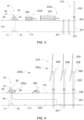
- FIG. 1 schematically represents a multipurpose buoy 10 according to an example of the present disclosure.
- the multipurpose buoy 10 of this example comprises a floating system.
- the floating system of this figure comprises a plurality of floats 11
- the floating system provides floatability to the multipurpose buoy 10.
- the floatability of the multipurpose buoy may be controlled by regulating the amount of water inside the floats 11.
- the floats 11 comprise a cylindrical shape.
- Linking members may be provided to connect the plurality of floats 11.
- the lidar 21 may measure wind speeds, wind turbulences, and wind direction. In some examples, the lidar 21 also measures air density. In further examples, air density may be obtained from an air density sensor, e.g. barometer. In some examples, the environmental sensor system 20 comprises an ocean sensor, a camera, a sonar, a temperature sensor, and an infrared sensor. The environmental sensor system 20 may comprise a plurality of sensors to measure different environmental parameters.
- the multipurpose buoy 10 comprises a carrying area.
- the carrying area may comprise a landing platform for unmanned aerial vehicles to land and take off.
- the charging station 30 is arranged on a landing platform 31.
- the landing platform 31 is configured to carry unmanned aerial vehicles.
- an electric boat may be docked on the landing platform 31.
- the unmanned aerial vehicles may be supported by the landing platform 31 while being charged by the charging station 30.
- the landing platform 31 may comprise elements, e.g. guiding marks or signals, to ease the landing or taking off of the unmanned aerial vehicle.
- the landing platform 31 may be arranged outside the inner chamber. In this example, the landing platform 31 outwardly extends from a side wall. In other examples, the landing platform 31 may be arranged at the upper wall of the support structure 12.
- the carrying area may be configured to carry a boat or an unmanned underwater vehicle.
- the carrying area may be an area arranged within the floats 11 or at the lower wall of the support structure 12.
- a gate may be arranged at the floats 11 or at the lower wall to allow the unmanned underwater vehicle to leave the multipurpose buoy.
- the onboard power source 41 may comprise at least one of photovoltaic modules, onboard wind turbines, and a fuel cell.
- the onboard power source 41 of this figure comprises a plurality of photovoltaic modules 43, a plurality of onboard wind turbines 42, and a fuel cell.
- the photovoltaic modules 43 are arranged on the side walls of the support structure 12.
- the onboard power source 41 of this example further comprises three onboard wind turbines 42.
- the onboard wind turbines 42 are connected at the upper end of three of the columns.
- onboard wind turbines should be understood as wind turbines configured to produce less than 1000 W, e.g. between 25 W and 250 W.
- the power system comprises a transformer to reduce the voltage provided by the external power source to a suitable voltage to be used by the multipurpose buoy 10.
- the transformer may be an AC or a DC transformer.
- the transformer may reduce the voltage of the power grid, AC or DC, to a suitable voltage.
- the multipurpose buoy 10 of figure 1 comprises a controller 50 arranged at the support structure 12. Communications between the environmental sensor system 20 and the controller 50 may thus be easily established. For example, the environmental sensor system 20 may be wiredly connected to the controller 50.
- the controller 50 is configured to control the power system to power the multipurpose buoy 10, at least based on the operational stage of the project of the offshore infrastructure and the offshore infrastructure itself.
- the availability of power may vary along the operational stages of the offshore infrastructure and its project.
- the multipurpose buoy 10 may only be powered by the onboard power source.
- the controller may adopt a conservative strategy to maintain a minimum energy quantity stored in the onboard energy storage system.
- this external energy source may be stored in the onboard energy storage system.
- the controller 50 may comprise to determine an amount of onboard power to be supplied and an amount of external power to be supplied. In some examples, this amount may be based on power availability.
- the controller 50 may be configured to obtain the operational stage of the plurality of operational stages of the offshore infrastructure and its project. For example, the controller may receive an indication, from an external computer system, about the operational stage of the project and the offshore infrastructure.
- the operational stages may comprise several states. Examples of these states for a production stage of an offshore wind farm may be a full power state or a partial power state. In a full power state, the offshore wind turbines are generating energy at their nominal power capacity. In a partial power state, the offshore wind turbines are generating less power than the nominal power. Further examples of states during the production stage of the offshore wind farm may be a full maintenance state or a partial maintenance state. In the full maintenance state, the wind farm is not generating energy and in the partial maintenance state some offshore wind turbines are generating energy, and others are stopped.
- the controller 50 may further be configured to obtain the state of the operational stages.
- the power source may also be controlled taking into account the obtained state.
- the controller 50 may be configured to determine a power demand of the multipurpose buoy 10, at least based on the operational stage of the offshore infrastructure.
- the controller may also take into account the specific state of the operational stage. Determining a power demand in advance may improve the management of the energy stored by the onboard energy storage system.
- Data obtained from the environmental sensor system 20 may be used for optimizing the design of wind turbines for this specific offshore site. Development and planning of the construction of the offshore wind farm may thus take into account this data.
- the design of the wind turbines may thus be adapted to the specific conditions of this offshore site. For example, control strategies may be defined to increase the energy captured from the wind while preserving the structural stability of the wind turbines.
- the controller 50 may receive data from the unmanned aerial vehicles 230a, 230b and 230c. This data may comprise charging status and operation status. In some examples, this data may also comprise data about the inspection of the offshore infrastructure.
- the method 300 comprises obtaining the operational stage of the offshore infrastructure.
- the controller may receive an indication of the operational stage.
- the method may further comprise obtaining the status of the operational stage.
- the controller may control the power system based on the operational stage.
Landscapes
- Engineering & Computer Science (AREA)
- Chemical & Material Sciences (AREA)
- Combustion & Propulsion (AREA)
- Mechanical Engineering (AREA)
- Ocean & Marine Engineering (AREA)
- Architecture (AREA)
- Civil Engineering (AREA)
- Structural Engineering (AREA)
- Charge And Discharge Circuits For Batteries Or The Like (AREA)
Priority Applications (2)
| Application Number | Priority Date | Filing Date | Title |
|---|---|---|---|
| EP23382005.9A EP4397586A1 (fr) | 2023-01-04 | 2023-01-04 | Bouée polyvalente pour supporter un projet d'une infrastructure en mer et l'infrastructure en mer |
| PCT/EP2023/087701 WO2024146844A1 (fr) | 2023-01-04 | 2023-12-22 | Bouée polyvalente pour prendre en charge un projet d'une infrastructure en mer, et infrastructure en mer |
Applications Claiming Priority (1)
| Application Number | Priority Date | Filing Date | Title |
|---|---|---|---|
| EP23382005.9A EP4397586A1 (fr) | 2023-01-04 | 2023-01-04 | Bouée polyvalente pour supporter un projet d'une infrastructure en mer et l'infrastructure en mer |
Publications (1)
| Publication Number | Publication Date |
|---|---|
| EP4397586A1 true EP4397586A1 (fr) | 2024-07-10 |
Family
ID=84829553
Family Applications (1)
| Application Number | Title | Priority Date | Filing Date |
|---|---|---|---|
| EP23382005.9A Pending EP4397586A1 (fr) | 2023-01-04 | 2023-01-04 | Bouée polyvalente pour supporter un projet d'une infrastructure en mer et l'infrastructure en mer |
Country Status (2)
| Country | Link |
|---|---|
| EP (1) | EP4397586A1 (fr) |
| WO (1) | WO2024146844A1 (fr) |
Citations (5)
| Publication number | Priority date | Publication date | Assignee | Title |
|---|---|---|---|---|
| US20180364740A1 (en) * | 2017-06-20 | 2018-12-20 | Planck Aerosystems Inc. | Systems and methods for charging unmanned aerial vehicles on a moving platform |
| US20190202530A1 (en) * | 2018-01-03 | 2019-07-04 | Hadal, Inc. | Incremental deployment of a buoy or buoy network |
| US20190233060A1 (en) * | 2018-01-27 | 2019-08-01 | Lone Gull Holdings, Ltd. | Wind-powered computing buoy |
| EP3180238B1 (fr) * | 2014-08-12 | 2020-06-24 | University of Maine System Board of Trustees | Bouée avec compensation de mouvement intégrée |
| EP3653482B1 (fr) * | 2018-11-16 | 2021-07-28 | Ocean Power Technologies, Inc. | Bloc-batterie marine sous la surface |
-
2023
- 2023-01-04 EP EP23382005.9A patent/EP4397586A1/fr active Pending
- 2023-12-22 WO PCT/EP2023/087701 patent/WO2024146844A1/fr not_active Ceased
Patent Citations (5)
| Publication number | Priority date | Publication date | Assignee | Title |
|---|---|---|---|---|
| EP3180238B1 (fr) * | 2014-08-12 | 2020-06-24 | University of Maine System Board of Trustees | Bouée avec compensation de mouvement intégrée |
| US20180364740A1 (en) * | 2017-06-20 | 2018-12-20 | Planck Aerosystems Inc. | Systems and methods for charging unmanned aerial vehicles on a moving platform |
| US20190202530A1 (en) * | 2018-01-03 | 2019-07-04 | Hadal, Inc. | Incremental deployment of a buoy or buoy network |
| US20190233060A1 (en) * | 2018-01-27 | 2019-08-01 | Lone Gull Holdings, Ltd. | Wind-powered computing buoy |
| EP3653482B1 (fr) * | 2018-11-16 | 2021-07-28 | Ocean Power Technologies, Inc. | Bloc-batterie marine sous la surface |
Also Published As
| Publication number | Publication date |
|---|---|
| WO2024146844A1 (fr) | 2024-07-11 |
Similar Documents
| Publication | Publication Date | Title |
|---|---|---|
| CN108482595A (zh) | 海上漂浮发电平台与无人艇集群的组合系统及工作方法 | |
| US8169099B2 (en) | Deep offshore floating wind turbine and method of deep offshore floating wind turbine assembly, transportation, installation and operation | |
| CN103147903B (zh) | 一种无人驾驶自主导航海洋观测平台 | |
| JP7142914B2 (ja) | 再生可能なエネルギバージ船 | |
| CN111640220A (zh) | 一种用于海上风电场的无人船巡检系统及其工作方法 | |
| CN104948380B (zh) | 一种波浪能光伏与海上风机联合发电系统 | |
| Parwal et al. | Wave energy research at Uppsala University and the Lysekil Research Site, Sweden: A status update | |
| US20250036142A1 (en) | A surveillance system for an offshore infrastructure | |
| US12270370B2 (en) | Adaptive control of wave energy converters | |
| Driscoll et al. | A 20 kW open ocean current test turbine | |
| US12189353B2 (en) | Watercraft servicing system | |
| EP4397586A1 (fr) | Bouée polyvalente pour supporter un projet d'une infrastructure en mer et l'infrastructure en mer | |
| JP5002760B2 (ja) | 無人浮流物質監視用ブイ、浮流物質監視システム及び浮流物質監視方法 | |
| Udvardy et al. | Inspection of wind power plant turbines by using UAV | |
| JP7810019B2 (ja) | 点検装置 | |
| Murray | Abuoyant future for offshore wind: Floating wind systems are on the cusp of a huge transformation as they transition from pilot projects to commercial-sized wind farms | |
| CN204937448U (zh) | 一种风光互补水面机器人 | |
| CN212256394U (zh) | 一种用于海上风电场的无人船巡检系统 | |
| Alessi et al. | Application of wave energy converter technology to subsea power requirements and asset integrity in oil and gas field developments | |
| CN115450847A (zh) | 一种海上风电塔筒关联信息交互网状系统 | |
| CN117028123B (zh) | 一种水下结构物健康监测系统 | |
| Dhanak et al. | Development of an unmanned mobile current turbine platform | |
| RU2343084C2 (ru) | Самоходная полупогружная океанологическая исследовательская платформа и способ ее использования | |
| CN120728745B (zh) | 海上漂浮式风光互补发电方法、系统及设备 | |
| Dach | Eidesstattliche Erklärung |
Legal Events
| Date | Code | Title | Description |
|---|---|---|---|
| PUAI | Public reference made under article 153(3) epc to a published international application that has entered the european phase |
Free format text: ORIGINAL CODE: 0009012 |
|
| STAA | Information on the status of an ep patent application or granted ep patent |
Free format text: STATUS: THE APPLICATION HAS BEEN PUBLISHED |
|
| AK | Designated contracting states |
Kind code of ref document: A1 Designated state(s): AL AT BE BG CH CY CZ DE DK EE ES FI FR GB GR HR HU IE IS IT LI LT LU LV MC ME MK MT NL NO PL PT RO RS SE SI SK SM TR |
|
| STAA | Information on the status of an ep patent application or granted ep patent |
Free format text: STATUS: REQUEST FOR EXAMINATION WAS MADE |
|
| 17P | Request for examination filed |
Effective date: 20250110 |