EP4397600A1 - Flüssigwasserstofftank und verfahren zum entwurf davon - Google Patents
Flüssigwasserstofftank und verfahren zum entwurf davon Download PDFInfo
- Publication number
- EP4397600A1 EP4397600A1 EP22864201.3A EP22864201A EP4397600A1 EP 4397600 A1 EP4397600 A1 EP 4397600A1 EP 22864201 A EP22864201 A EP 22864201A EP 4397600 A1 EP4397600 A1 EP 4397600A1
- Authority
- EP
- European Patent Office
- Prior art keywords
- tank
- leakage prevention
- wall thickness
- liquefied hydrogen
- inner shell
- Prior art date
- Legal status (The legal status is an assumption and is not a legal conclusion. Google has not performed a legal analysis and makes no representation as to the accuracy of the status listed.)
- Pending
Links
Images


Classifications
-
- B—PERFORMING OPERATIONS; TRANSPORTING
- B63—SHIPS OR OTHER WATERBORNE VESSELS; RELATED EQUIPMENT
- B63B—SHIPS OR OTHER WATERBORNE VESSELS; EQUIPMENT FOR SHIPPING
- B63B25/00—Load-accommodating arrangements, e.g. stowing, trimming; Vessels characterised thereby
- B63B25/02—Load-accommodating arrangements, e.g. stowing, trimming; Vessels characterised thereby for bulk goods
- B63B25/08—Load-accommodating arrangements, e.g. stowing, trimming; Vessels characterised thereby for bulk goods fluid
- B63B25/12—Load-accommodating arrangements, e.g. stowing, trimming; Vessels characterised thereby for bulk goods fluid closed
- B63B25/16—Load-accommodating arrangements, e.g. stowing, trimming; Vessels characterised thereby for bulk goods fluid closed heat-insulated
-
- B—PERFORMING OPERATIONS; TRANSPORTING
- B63—SHIPS OR OTHER WATERBORNE VESSELS; RELATED EQUIPMENT
- B63B—SHIPS OR OTHER WATERBORNE VESSELS; EQUIPMENT FOR SHIPPING
- B63B71/00—Designing vessels; Predicting their performance
-
- F—MECHANICAL ENGINEERING; LIGHTING; HEATING; WEAPONS; BLASTING
- F17—STORING OR DISTRIBUTING GASES OR LIQUIDS
- F17C—VESSELS FOR CONTAINING OR STORING COMPRESSED, LIQUEFIED OR SOLIDIFIED GASES; FIXED-CAPACITY GAS-HOLDERS; FILLING VESSELS WITH, OR DISCHARGING FROM VESSELS, COMPRESSED, LIQUEFIED, OR SOLIDIFIED GASES
- F17C3/00—Vessels not under pressure
- F17C3/02—Vessels not under pressure with provision for thermal insulation
- F17C3/025—Bulk storage in barges or on ships
-
- G—PHYSICS
- G06—COMPUTING OR CALCULATING; COUNTING
- G06F—ELECTRIC DIGITAL DATA PROCESSING
- G06F30/00—Computer-aided design [CAD]
- G06F30/10—Geometric CAD
- G06F30/15—Vehicle, aircraft or watercraft design
-
- G—PHYSICS
- G06—COMPUTING OR CALCULATING; COUNTING
- G06F—ELECTRIC DIGITAL DATA PROCESSING
- G06F30/00—Computer-aided design [CAD]
- G06F30/10—Geometric CAD
- G06F30/18—Network design, e.g. design based on topological or interconnect aspects of utility systems, piping, heating ventilation air conditioning [HVAC] or cabling
-
- G—PHYSICS
- G06—COMPUTING OR CALCULATING; COUNTING
- G06F—ELECTRIC DIGITAL DATA PROCESSING
- G06F30/00—Computer-aided design [CAD]
- G06F30/20—Design optimisation, verification or simulation
-
- G—PHYSICS
- G06—COMPUTING OR CALCULATING; COUNTING
- G06F—ELECTRIC DIGITAL DATA PROCESSING
- G06F30/00—Computer-aided design [CAD]
- G06F30/20—Design optimisation, verification or simulation
- G06F30/23—Design optimisation, verification or simulation using finite element methods [FEM] or finite difference methods [FDM]
-
- F—MECHANICAL ENGINEERING; LIGHTING; HEATING; WEAPONS; BLASTING
- F17—STORING OR DISTRIBUTING GASES OR LIQUIDS
- F17C—VESSELS FOR CONTAINING OR STORING COMPRESSED, LIQUEFIED OR SOLIDIFIED GASES; FIXED-CAPACITY GAS-HOLDERS; FILLING VESSELS WITH, OR DISCHARGING FROM VESSELS, COMPRESSED, LIQUEFIED, OR SOLIDIFIED GASES
- F17C2201/00—Vessel construction, in particular geometry, arrangement or size
- F17C2201/01—Shape
- F17C2201/0128—Shape spherical or elliptical
-
- F—MECHANICAL ENGINEERING; LIGHTING; HEATING; WEAPONS; BLASTING
- F17—STORING OR DISTRIBUTING GASES OR LIQUIDS
- F17C—VESSELS FOR CONTAINING OR STORING COMPRESSED, LIQUEFIED OR SOLIDIFIED GASES; FIXED-CAPACITY GAS-HOLDERS; FILLING VESSELS WITH, OR DISCHARGING FROM VESSELS, COMPRESSED, LIQUEFIED, OR SOLIDIFIED GASES
- F17C2201/00—Vessel construction, in particular geometry, arrangement or size
- F17C2201/05—Size
- F17C2201/052—Size large (>1000 m3)
-
- F—MECHANICAL ENGINEERING; LIGHTING; HEATING; WEAPONS; BLASTING
- F17—STORING OR DISTRIBUTING GASES OR LIQUIDS
- F17C—VESSELS FOR CONTAINING OR STORING COMPRESSED, LIQUEFIED OR SOLIDIFIED GASES; FIXED-CAPACITY GAS-HOLDERS; FILLING VESSELS WITH, OR DISCHARGING FROM VESSELS, COMPRESSED, LIQUEFIED, OR SOLIDIFIED GASES
- F17C2203/00—Vessel construction, in particular walls or details thereof
- F17C2203/03—Thermal insulations
- F17C2203/0375—Thermal insulations by gas
-
- F—MECHANICAL ENGINEERING; LIGHTING; HEATING; WEAPONS; BLASTING
- F17—STORING OR DISTRIBUTING GASES OR LIQUIDS
- F17C—VESSELS FOR CONTAINING OR STORING COMPRESSED, LIQUEFIED OR SOLIDIFIED GASES; FIXED-CAPACITY GAS-HOLDERS; FILLING VESSELS WITH, OR DISCHARGING FROM VESSELS, COMPRESSED, LIQUEFIED, OR SOLIDIFIED GASES
- F17C2203/00—Vessel construction, in particular walls or details thereof
- F17C2203/03—Thermal insulations
- F17C2203/0391—Thermal insulations by vacuum
-
- F—MECHANICAL ENGINEERING; LIGHTING; HEATING; WEAPONS; BLASTING
- F17—STORING OR DISTRIBUTING GASES OR LIQUIDS
- F17C—VESSELS FOR CONTAINING OR STORING COMPRESSED, LIQUEFIED OR SOLIDIFIED GASES; FIXED-CAPACITY GAS-HOLDERS; FILLING VESSELS WITH, OR DISCHARGING FROM VESSELS, COMPRESSED, LIQUEFIED, OR SOLIDIFIED GASES
- F17C2203/00—Vessel construction, in particular walls or details thereof
- F17C2203/06—Materials for walls or layers thereof; Properties or structures of walls or their materials
- F17C2203/0602—Wall structures; Special features thereof
- F17C2203/0612—Wall structures
- F17C2203/0626—Multiple walls
- F17C2203/0629—Two walls
-
- F—MECHANICAL ENGINEERING; LIGHTING; HEATING; WEAPONS; BLASTING
- F17—STORING OR DISTRIBUTING GASES OR LIQUIDS
- F17C—VESSELS FOR CONTAINING OR STORING COMPRESSED, LIQUEFIED OR SOLIDIFIED GASES; FIXED-CAPACITY GAS-HOLDERS; FILLING VESSELS WITH, OR DISCHARGING FROM VESSELS, COMPRESSED, LIQUEFIED, OR SOLIDIFIED GASES
- F17C2203/00—Vessel construction, in particular walls or details thereof
- F17C2203/06—Materials for walls or layers thereof; Properties or structures of walls or their materials
- F17C2203/0602—Wall structures; Special features thereof
- F17C2203/0612—Wall structures
- F17C2203/0626—Multiple walls
- F17C2203/0631—Three or more walls
-
- F—MECHANICAL ENGINEERING; LIGHTING; HEATING; WEAPONS; BLASTING
- F17—STORING OR DISTRIBUTING GASES OR LIQUIDS
- F17C—VESSELS FOR CONTAINING OR STORING COMPRESSED, LIQUEFIED OR SOLIDIFIED GASES; FIXED-CAPACITY GAS-HOLDERS; FILLING VESSELS WITH, OR DISCHARGING FROM VESSELS, COMPRESSED, LIQUEFIED, OR SOLIDIFIED GASES
- F17C2203/00—Vessel construction, in particular walls or details thereof
- F17C2203/06—Materials for walls or layers thereof; Properties or structures of walls or their materials
- F17C2203/0634—Materials for walls or layers thereof
- F17C2203/0636—Metals
- F17C2203/0639—Steels
-
- F—MECHANICAL ENGINEERING; LIGHTING; HEATING; WEAPONS; BLASTING
- F17—STORING OR DISTRIBUTING GASES OR LIQUIDS
- F17C—VESSELS FOR CONTAINING OR STORING COMPRESSED, LIQUEFIED OR SOLIDIFIED GASES; FIXED-CAPACITY GAS-HOLDERS; FILLING VESSELS WITH, OR DISCHARGING FROM VESSELS, COMPRESSED, LIQUEFIED, OR SOLIDIFIED GASES
- F17C2205/00—Vessel construction, in particular mounting arrangements, attachments or identifications means
- F17C2205/01—Mounting arrangements
- F17C2205/0153—Details of mounting arrangements
- F17C2205/018—Supporting feet
-
- F—MECHANICAL ENGINEERING; LIGHTING; HEATING; WEAPONS; BLASTING
- F17—STORING OR DISTRIBUTING GASES OR LIQUIDS
- F17C—VESSELS FOR CONTAINING OR STORING COMPRESSED, LIQUEFIED OR SOLIDIFIED GASES; FIXED-CAPACITY GAS-HOLDERS; FILLING VESSELS WITH, OR DISCHARGING FROM VESSELS, COMPRESSED, LIQUEFIED, OR SOLIDIFIED GASES
- F17C2221/00—Handled fluid, in particular type of fluid
- F17C2221/01—Pure fluids
- F17C2221/012—Hydrogen
-
- F—MECHANICAL ENGINEERING; LIGHTING; HEATING; WEAPONS; BLASTING
- F17—STORING OR DISTRIBUTING GASES OR LIQUIDS
- F17C—VESSELS FOR CONTAINING OR STORING COMPRESSED, LIQUEFIED OR SOLIDIFIED GASES; FIXED-CAPACITY GAS-HOLDERS; FILLING VESSELS WITH, OR DISCHARGING FROM VESSELS, COMPRESSED, LIQUEFIED, OR SOLIDIFIED GASES
- F17C2223/00—Handled fluid before transfer, i.e. state of fluid when stored in the vessel or before transfer from the vessel
- F17C2223/01—Handled fluid before transfer, i.e. state of fluid when stored in the vessel or before transfer from the vessel characterised by the phase
- F17C2223/0146—Two-phase
- F17C2223/0153—Liquefied gas, e.g. LPG, GPL
- F17C2223/0161—Liquefied gas, e.g. LPG, GPL cryogenic, e.g. LNG, GNL, PLNG
-
- F—MECHANICAL ENGINEERING; LIGHTING; HEATING; WEAPONS; BLASTING
- F17—STORING OR DISTRIBUTING GASES OR LIQUIDS
- F17C—VESSELS FOR CONTAINING OR STORING COMPRESSED, LIQUEFIED OR SOLIDIFIED GASES; FIXED-CAPACITY GAS-HOLDERS; FILLING VESSELS WITH, OR DISCHARGING FROM VESSELS, COMPRESSED, LIQUEFIED, OR SOLIDIFIED GASES
- F17C2223/00—Handled fluid before transfer, i.e. state of fluid when stored in the vessel or before transfer from the vessel
- F17C2223/03—Handled fluid before transfer, i.e. state of fluid when stored in the vessel or before transfer from the vessel characterised by the pressure level
- F17C2223/033—Small pressure, e.g. for liquefied gas
-
- F—MECHANICAL ENGINEERING; LIGHTING; HEATING; WEAPONS; BLASTING
- F17—STORING OR DISTRIBUTING GASES OR LIQUIDS
- F17C—VESSELS FOR CONTAINING OR STORING COMPRESSED, LIQUEFIED OR SOLIDIFIED GASES; FIXED-CAPACITY GAS-HOLDERS; FILLING VESSELS WITH, OR DISCHARGING FROM VESSELS, COMPRESSED, LIQUEFIED, OR SOLIDIFIED GASES
- F17C2250/00—Accessories; Control means; Indicating, measuring or monitoring of parameters
- F17C2250/03—Control means
- F17C2250/032—Control means using computers
-
- F—MECHANICAL ENGINEERING; LIGHTING; HEATING; WEAPONS; BLASTING
- F17—STORING OR DISTRIBUTING GASES OR LIQUIDS
- F17C—VESSELS FOR CONTAINING OR STORING COMPRESSED, LIQUEFIED OR SOLIDIFIED GASES; FIXED-CAPACITY GAS-HOLDERS; FILLING VESSELS WITH, OR DISCHARGING FROM VESSELS, COMPRESSED, LIQUEFIED, OR SOLIDIFIED GASES
- F17C2260/00—Purposes of gas storage and gas handling
- F17C2260/01—Improving mechanical properties or manufacturing
- F17C2260/011—Improving strength
-
- F—MECHANICAL ENGINEERING; LIGHTING; HEATING; WEAPONS; BLASTING
- F17—STORING OR DISTRIBUTING GASES OR LIQUIDS
- F17C—VESSELS FOR CONTAINING OR STORING COMPRESSED, LIQUEFIED OR SOLIDIFIED GASES; FIXED-CAPACITY GAS-HOLDERS; FILLING VESSELS WITH, OR DISCHARGING FROM VESSELS, COMPRESSED, LIQUEFIED, OR SOLIDIFIED GASES
- F17C2270/00—Applications
- F17C2270/01—Applications for fluid transport or storage
- F17C2270/0102—Applications for fluid transport or storage on or in the water
- F17C2270/0105—Ships
-
- G—PHYSICS
- G06—COMPUTING OR CALCULATING; COUNTING
- G06F—ELECTRIC DIGITAL DATA PROCESSING
- G06F2111/00—Details relating to CAD techniques
- G06F2111/10—Numerical modelling
-
- G—PHYSICS
- G06—COMPUTING OR CALCULATING; COUNTING
- G06F—ELECTRIC DIGITAL DATA PROCESSING
- G06F2119/00—Details relating to the type or aim of the analysis or the optimisation
- G06F2119/02—Reliability analysis or reliability optimisation; Failure analysis, e.g. worst case scenario performance, failure mode and effects analysis [FMEA]
-
- G—PHYSICS
- G06—COMPUTING OR CALCULATING; COUNTING
- G06F—ELECTRIC DIGITAL DATA PROCESSING
- G06F2119/00—Details relating to the type or aim of the analysis or the optimisation
- G06F2119/04—Ageing analysis or optimisation against ageing
-
- G—PHYSICS
- G06—COMPUTING OR CALCULATING; COUNTING
- G06F—ELECTRIC DIGITAL DATA PROCESSING
- G06F2119/00—Details relating to the type or aim of the analysis or the optimisation
- G06F2119/14—Force analysis or force optimisation, e.g. static or dynamic forces
-
- Y—GENERAL TAGGING OF NEW TECHNOLOGICAL DEVELOPMENTS; GENERAL TAGGING OF CROSS-SECTIONAL TECHNOLOGIES SPANNING OVER SEVERAL SECTIONS OF THE IPC; TECHNICAL SUBJECTS COVERED BY FORMER USPC CROSS-REFERENCE ART COLLECTIONS [XRACs] AND DIGESTS
- Y02—TECHNOLOGIES OR APPLICATIONS FOR MITIGATION OR ADAPTATION AGAINST CLIMATE CHANGE
- Y02E—REDUCTION OF GREENHOUSE GAS [GHG] EMISSIONS, RELATED TO ENERGY GENERATION, TRANSMISSION OR DISTRIBUTION
- Y02E60/00—Enabling technologies; Technologies with a potential or indirect contribution to GHG emissions mitigation
- Y02E60/30—Hydrogen technology
- Y02E60/32—Hydrogen storage
Definitions
- the present disclosure relates to the structure of a liquefied hydrogen tank mounted on a ship (hereinafter referred to as a liquefied hydrogen carrier) that transports liquid hydrogen, and a method of designing the liquefied hydrogen tank.
- a cargo tank of a liquefied hydrogen carrier is a cargo tank including: an inner shell storing liquefied hydrogen; an outer shell surrounding the inner shell; and a heat insulating layer located between the inner shell and the outer shell.
- PTL 1 discloses one example of the cargo tank of the liquefied hydrogen carrier.
- IGC Code Designing and building a ship that transports a liquefied gas are required to be based on the IGC Code (NPTL 1) that is the International Code.
- the current IGC Code is directed to ships that transport liquefied gases, such as LPG and LNG, and is not directed to liquefied hydrogen carriers, and requirements regarding the transportation of the liquid hydrogen have not been defined.
- NPTL 1 International Maritime Organization, "THE INTERNATIONAL CODE FOR THE CONSTRUCTION AND EQUIPMENT OF SHIPS CARRYING LIQUEFIED GASES IN BULK (IGC CODE)" CHAPTER 4 CARGO CONTAINMENT, adopted on 22 May 2014
- the present disclosure was made under these circumstances, and an object of the present disclosure is to propose, to realize mass transportation of cryogenic liquefied hydrogen, the structure of a liquefied hydrogen tank mounted on a ship and a method of designing the liquefied hydrogen tank, the structure and the method being able to prevent hydrogen of a liquid form or a gas form from leaking regardless of the scale of the liquefied hydrogen tank.
- a liquefied hydrogen tank is a liquefied hydrogen tank mounted on a ship.
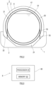
- the liquefied hydrogen tank includes: an inner shell storing liquefied hydrogen; and an outer shell surrounding the inner shell. At least one of the inner shell or the outer shell is a leakage prevention tank.
- the leakage prevention tank has such a wall thickness that an initial defect is not propagated beyond a half of a thickness of a wall of the leakage prevention tank during a tank life of the leakage prevention tank.
- a method of designing a liquefied hydrogen tank according to the present disclosure is a method of designing a liquefied hydrogen tank which is mounted on a ship and includes an inner shell storing liquefied hydrogen and an outer shell surrounding the inner shell, at least one of the inner shell or the outer shell being a leakage prevention tank.
- the method includes: acquiring, by a first processor, a tank life of the leakage prevention tank, a size of an initial defect of the leakage prevention tank, a temperature of the leakage prevention tank, a stress intensity factor of the leakage prevention tank, and stress generated at the leakage prevention tank; calculating, by the first processor by fatigue crack propagation analysis, a crack propagation amount of the initial defect which is propagated by the stress having the number of cycles corresponding to the tank life; acquiring, by a second processor, the calculated crack propagation amount and a design wall thickness of the leakage prevention tank; when the crack propagation amount does not exceed a half of the design wall thickness, judging by the second processor that the design wall thickness is appropriate; when the crack propagation amount exceeds the half of the design wall thickness, judging by the second processor that the design wall thickness is inappropriate; and determining a wall thickness of the leakage prevention tank such that the wall thickness becomes not less than the design wall thickness which has been judged to be appropriate.
- the liquefied hydrogen tank 3 does not include a vacuum heat insulating system.
- a vacuum heat insulating layer may be located between the inner shell 4 and the outer shell 5 in such a manner that a heat insulating layer is located in the first region 31, and the first region 31 is set to a vacuum state.
- the second region 32 filled with the second gas has substantially atmospheric pressure.
- the pressure of the second region 32 is not especially limited but may be higher than the pressure of the first region 31.
- the second gas contains at least one of: an inert gas, such as nitrogen; or dry air.
- the second region 32 may be filled with the dry air, and the inert gas may be held by the second heat insulating layer.
- the tank type of the liquefied hydrogen tank 3 will be described in detail.
- At least one of the inner shell 4 or the outer shell 5 is a leakage prevention tank.
- the leakage prevention tank has such a wall thickness that an initial defect is not propagated beyond a half of the thickness of a wall of the leakage prevention tank during a tank life of the leakage prevention tank. Since the assumed propagation of the initial defect in such leakage prevention tank is adequately small with respect to the wall thickness (tank thickness), the leakage of the liquid or gas stored in the leakage prevention tank is not assumed.
- the leakage prevention tank defined as above corresponds to a Type-C tank defined in the IGC Code from the viewpoint that the leakage of the stored liquid or gas is not assumed.
- a stress analysis method performed by the stress analyzing part 84 is not especially limited, and examples thereof include: a numerical analysis method, such as a finite element method; and simulation.
- the stress analyzing part 84 can calculate generated stress (generated stress distribution of the leakage prevention tank) estimated by: acquiring a fluctuating load generated due to the ship motion of the hull 2 by the waves during sailing and the waves received by the hull 2; applying this fluctuating load to a numerical analysis model of the entire ship 1 including a hull structure, a leakage prevention tank structure, and a tank support structure; and executing numerical analysis.
- a set wall thickness is incorporated as a parameter in the leakage prevention tank structure.
- the fluctuating load and the numerical analysis model may be given to the stress analyzing part 84 in advance.
- the fluctuating load can be calculated based on the state of the route of the ship 1 by simulation or experiment.
- the fatigue crack propagation analyzing part 85 calculates the crack propagation amount of the initial defect of the leakage prevention tank by fatigue crack propagation analysis.
- the fatigue crack propagation analysis method performed by the fatigue crack propagation analyzing part 85 is not especially limited, and examples thereof include: a numerical analysis method, such as a finite element method; and simulation.
- the fatigue crack propagation analyzing part 85 can calculate the crack propagation amount of the initial defect during the tank life by: acquiring the tank life of the leakage prevention tank, fracture toughness of a material of the leakage prevention tank, the stress intensity factor of the analysis target portion, and the generated stress of the analysis target portion; applying these to a fatigue crack propagation analysis model; and executing the numerical analysis.
- the judging part 87 judges that the design wall thickness is "appropriate.” When the requirement is not satisfied, the judging part 87 judges that the design wall thickness is "inappropriate.” Specifically, the judging part 87 acquires the crack propagation amount of the initial defect during the tank life which has been calculated by the fatigue crack propagation analyzing part 85. When the crack propagation amount does not exceed the half of the design wall thickness (i.e., when the crack propagation amount is not more than the half of the design wall thickness), the judging part 87 judges that the design wall thickness is appropriate. When the crack propagation amount exceeds the half of the design wall thickness, the judging part 87 judges that the design wall thickness is inappropriate.
- the liquefied hydrogen tank 3 is the liquefied hydrogen tank 3 mounted on the ship 1 and includes: the inner shell 4 storing the liquefied hydrogen; and the outer shell 5 surrounding the inner shell 4. At least one of the inner shell 4 or the outer shell 5 is the leakage prevention tank.
- the leakage prevention tank has such a wall thickness that an initial defect is not propagated beyond a half of a thickness of a wall of the leakage prevention tank during a tank life of the leakage prevention tank.
- the hydrogen gas may be filled in a region between the inner shell 4 and the outer shell 5, and the outer shell 5 may be the leakage prevention tank.
- the tank which does not cause the leakage of the stored gas or liquid while having the wall thickness within a realistic range can be designed.
- the above method of designing the liquefied hydrogen tank 3 may further include: calculating, by a third processor (stress intensity factor analyzing part 86), as the judgement index the stress intensity factor of the crack generated in such a manner that the initial defect is propagated during the tank life; acquiring, by a fourth processor (wall thickness determining part 88), the fracture toughness value of the material of the leakage prevention tank; and when the judgement index is not less than the fracture toughness value, judging by the fourth processor that the design wall thickness is inappropriate, since the generation of the instable fracture during the tank life is assumed.
- the stress intensity factor may be calculated with respect to the shape of the final crack after the tank life or may be repeatedly calculated with respect to the shape of the crack which is being propagated during the tank life.
- the first to fourth processors may be physically the same processor or may be processors independent from each other.
- the inner shell 4 is typically classified as a large-scale tank.
- the inner shell 4 may be a tank classified as a small-scale tank having a volume of not more than 20,000 m 3 and may be the leakage prevention tank.
- the structure of the liquefied hydrogen tank 3 according to the present disclosure and the method of designing the liquefied hydrogen tank 3 according to the present disclosure may be applied to small-scale tanks and large-scale tanks of more than 50,000 m 3 regardless of the scale of the tank.
- the liquefied hydrogen tank 3 is the cargo tank.
- the structure of the liquefied hydrogen tank 3 according to the present disclosure and the method of designing the liquefied hydrogen tank 3 according to the present disclosure may be applied to a fuel tank mounted on the ship 1.
- the ship 1 is not limited to the liquefied hydrogen carrier.
Landscapes
- Engineering & Computer Science (AREA)
- Physics & Mathematics (AREA)
- Geometry (AREA)
- Theoretical Computer Science (AREA)
- General Physics & Mathematics (AREA)
- General Engineering & Computer Science (AREA)
- Mechanical Engineering (AREA)
- Evolutionary Computation (AREA)
- Computer Hardware Design (AREA)
- Chemical & Material Sciences (AREA)
- Ocean & Marine Engineering (AREA)
- Combustion & Propulsion (AREA)
- Mathematical Analysis (AREA)
- Computational Mathematics (AREA)
- Pure & Applied Mathematics (AREA)
- Mathematical Optimization (AREA)
- Automation & Control Theory (AREA)
- Aviation & Aerospace Engineering (AREA)
- Thermal Sciences (AREA)
- Computer Networks & Wireless Communication (AREA)
- Filling Or Discharging Of Gas Storage Vessels (AREA)
Applications Claiming Priority (2)
| Application Number | Priority Date | Filing Date | Title |
|---|---|---|---|
| JP2021144154A JP7739094B2 (ja) | 2021-09-03 | 2021-09-03 | 液化水素タンクの設計方法 |
| PCT/JP2022/030428 WO2023032615A1 (ja) | 2021-09-03 | 2022-08-09 | 液化水素タンク及びその設計方法 |
Publications (2)
| Publication Number | Publication Date |
|---|---|
| EP4397600A1 true EP4397600A1 (de) | 2024-07-10 |
| EP4397600A4 EP4397600A4 (de) | 2025-08-20 |
Family
ID=85412238
Family Applications (1)
| Application Number | Title | Priority Date | Filing Date |
|---|---|---|---|
| EP22864201.3A Pending EP4397600A4 (de) | 2021-09-03 | 2022-08-09 | Flüssigwasserstofftank und verfahren zum entwurf davon |
Country Status (5)
| Country | Link |
|---|---|
| EP (1) | EP4397600A4 (de) |
| JP (1) | JP7739094B2 (de) |
| KR (1) | KR20240047398A (de) |
| CN (1) | CN117836221A (de) |
| WO (1) | WO2023032615A1 (de) |
Families Citing this family (2)
| Publication number | Priority date | Publication date | Assignee | Title |
|---|---|---|---|---|
| WO2025196931A1 (ja) * | 2024-03-19 | 2025-09-25 | 川崎重工業株式会社 | 船体のタンク支持構造及び液化ガス運搬船 |
| CN119284087A (zh) * | 2024-09-27 | 2025-01-10 | 江南造船(集团)有限责任公司 | 一种半船起浮总纵强度评估方法 |
Family Cites Families (11)
| Publication number | Priority date | Publication date | Assignee | Title |
|---|---|---|---|---|
| TW359736B (en) * | 1997-06-20 | 1999-06-01 | Exxon Production Research Co | Systems for vehicular, land-based distribution of liquefied natural gas |
| JP4975692B2 (ja) * | 2008-07-16 | 2012-07-11 | 新日本製鐵株式会社 | 燃料タンク |
| JP5785118B2 (ja) * | 2012-03-06 | 2015-09-24 | 三井造船株式会社 | 船舶、洋上浮体式設備、及び液化天然ガス貯蔵方法 |
| JP6027678B2 (ja) | 2013-04-23 | 2016-11-16 | 川崎重工業株式会社 | 船舶用二重殻タンク構造および液化ガス運搬船 |
| JP5863900B2 (ja) * | 2014-07-24 | 2016-02-17 | 三井造船株式会社 | 液化ガス輸送船、及び、液化ガス輸送船の設計方法 |
| CN205221610U (zh) * | 2015-12-03 | 2016-05-11 | 新疆联诚重工科技有限公司 | 一种防泄漏双层油罐 |
| GB201702362D0 (en) * | 2017-02-14 | 2017-03-29 | Univ Ulster | Composite pressure vessel for hydrogen storage |
| CN107618779A (zh) * | 2017-10-17 | 2018-01-23 | 四川鑫福石油化工设备制造有限责任公司 | 一种新型防泄漏双层油罐 |
| KR20190054846A (ko) * | 2017-11-14 | 2019-05-22 | 유병용 | 이중압력용기 |
| KR102662477B1 (ko) * | 2019-04-05 | 2024-05-03 | 카와사키 주코교 카부시키 카이샤 | 액화 가스 탱크 및 액화 가스 운반선 |
| JP7527107B2 (ja) * | 2019-12-27 | 2024-08-02 | 三菱造船株式会社 | カーゴタンクユニット及び船舶 |
-
2021
- 2021-09-03 JP JP2021144154A patent/JP7739094B2/ja active Active
-
2022
- 2022-08-09 EP EP22864201.3A patent/EP4397600A4/de active Pending
- 2022-08-09 CN CN202280054131.0A patent/CN117836221A/zh active Pending
- 2022-08-09 WO PCT/JP2022/030428 patent/WO2023032615A1/ja not_active Ceased
- 2022-08-09 KR KR1020247007791A patent/KR20240047398A/ko active Pending
Also Published As
| Publication number | Publication date |
|---|---|
| WO2023032615A1 (ja) | 2023-03-09 |
| KR20240047398A (ko) | 2024-04-12 |
| JP7739094B2 (ja) | 2025-09-16 |
| CN117836221A (zh) | 2024-04-05 |
| EP4397600A4 (de) | 2025-08-20 |
| JP2023037410A (ja) | 2023-03-15 |
Similar Documents
| Publication | Publication Date | Title |
|---|---|---|
| EP4397600A1 (de) | Flüssigwasserstofftank und verfahren zum entwurf davon | |
| Kim et al. | Design of Independent Type‐B LNG Fuel Tank: Comparative Study between Finite Element Analysis and International Guidance | |
| CN104443283B (zh) | 应用于b型独立舱的局部次屏壁系统及船舶或海洋结构物 | |
| Gavory et al. | Sloshing in membrane LNG carriers and its consequences from a designer’s perspective | |
| Jeong et al. | Calculation of boil-off gas (BOG) generation of KC-1 membrane LNG tank with high density rigid polyurethane foam by numerical analysis | |
| KR102749075B1 (ko) | 연료 탱크, 및 선박 | |
| Kim et al. | Development of strength evaluation methodology for independent IMO TYPE C tank with LH2 carriers | |
| KR20230160381A (ko) | 다중각 탱크, 선박 및 가스압 조정 방법 | |
| KR20170022667A (ko) | 액화가스 저장탱크의 누출 액화가스 처리 시스템 및 방법 | |
| WO2021200829A1 (ja) | 液化ガス貯留船 | |
| KR102687769B1 (ko) | 선박 | |
| Lee et al. | New methodology for estimating the minimum design vapor pressure of prismatic pressure vessel for on-ship application | |
| KR20220138540A (ko) | 액화가스 저장탱크 및 이를 구비한 선박 | |
| KR100762368B1 (ko) | 선박의 초기 설계 방법 | |
| Choi et al. | Estimation of the design pressure of a prismatic LNG storage vessel | |
| KR20090110490A (ko) | 슬러싱 저감 기능을 갖는 선박용 lng 저장탱크 구조 | |
| Moon et al. | Fire risk assessment of gas turbine propulsion system for LNG carriers | |
| KR102795513B1 (ko) | 액화 가스 탱크 설계 장치 및 이의 동작 방법 | |
| Tamura et al. | New LPG carrier adopting highly reliable cargo tank–IMO tank type B | |
| Schiaroli et al. | Consequence Analysis of a Bunkering Facility for Liquid Hydrogen Loading and Unloading | |
| Heo et al. | Structural assessment techniques for a newly developed LNG cargo containment system | |
| KR20240058370A (ko) | 다종의 연료를 충전할 수 있는 복합 벙커링선 | |
| KR20200048261A (ko) | 액화가스 저장용기 및 이를 구비한 선박 | |
| JP6282014B2 (ja) | 自立角型タンク及び船舶 | |
| KR102929671B1 (ko) | 액화가스 저장탱크 제작 방법, 액화가스 저장탱크 및 선박 |
Legal Events
| Date | Code | Title | Description |
|---|---|---|---|
| STAA | Information on the status of an ep patent application or granted ep patent |
Free format text: STATUS: THE INTERNATIONAL PUBLICATION HAS BEEN MADE |
|
| PUAI | Public reference made under article 153(3) epc to a published international application that has entered the european phase |
Free format text: ORIGINAL CODE: 0009012 |
|
| STAA | Information on the status of an ep patent application or granted ep patent |
Free format text: STATUS: REQUEST FOR EXAMINATION WAS MADE |
|
| 17P | Request for examination filed |
Effective date: 20240403 |
|
| AK | Designated contracting states |
Kind code of ref document: A1 Designated state(s): AL AT BE BG CH CY CZ DE DK EE ES FI FR GB GR HR HU IE IS IT LI LT LU LV MC MK MT NL NO PL PT RO RS SE SI SK SM TR |
|
| DAV | Request for validation of the european patent (deleted) | ||
| DAX | Request for extension of the european patent (deleted) | ||
| REG | Reference to a national code |
Ref country code: DE Ref legal event code: R079 Free format text: PREVIOUS MAIN CLASS: B65D0090220000 Ipc: F17C0003020000 |
|
| A4 | Supplementary search report drawn up and despatched |
Effective date: 20250723 |
|
| RIC1 | Information provided on ipc code assigned before grant |
Ipc: F17C 3/02 20060101AFI20250717BHEP Ipc: B65D 90/22 20060101ALI20250717BHEP Ipc: B63B 25/16 20060101ALI20250717BHEP Ipc: B63B 71/00 20200101ALI20250717BHEP Ipc: G06F 30/23 20200101ALI20250717BHEP Ipc: G06F 30/15 20200101ALI20250717BHEP Ipc: G06F 30/18 20200101ALI20250717BHEP Ipc: G06F 30/20 20200101ALI20250717BHEP |