EP4397801A2 - Tiroir - Google Patents
Tiroir Download PDFInfo
- Publication number
- EP4397801A2 EP4397801A2 EP24171519.2A EP24171519A EP4397801A2 EP 4397801 A2 EP4397801 A2 EP 4397801A2 EP 24171519 A EP24171519 A EP 24171519A EP 4397801 A2 EP4397801 A2 EP 4397801A2
- Authority
- EP
- European Patent Office
- Prior art keywords
- drawer
- treatment agent
- clothes treatment
- check valve
- storage container
- Prior art date
- Legal status (The legal status is an assumption and is not a legal conclusion. Google has not performed a legal analysis and makes no representation as to the accuracy of the status listed.)
- Pending
Links
Images








Classifications
-
- D—TEXTILES; PAPER
- D06—TREATMENT OF TEXTILES OR THE LIKE; LAUNDERING; FLEXIBLE MATERIALS NOT OTHERWISE PROVIDED FOR
- D06F—LAUNDERING, DRYING, IRONING, PRESSING OR FOLDING TEXTILE ARTICLES
- D06F39/00—Details of washing machines not specific to a single type of machines covered by groups D06F9/00 - D06F27/00
-
- D—TEXTILES; PAPER
- D06—TREATMENT OF TEXTILES OR THE LIKE; LAUNDERING; FLEXIBLE MATERIALS NOT OTHERWISE PROVIDED FOR
- D06F—LAUNDERING, DRYING, IRONING, PRESSING OR FOLDING TEXTILE ARTICLES
- D06F39/00—Details of washing machines not specific to a single type of machines covered by groups D06F9/00 - D06F27/00
- D06F39/02—Devices for adding soap or other washing agents
- D06F39/022—Devices for adding soap or other washing agents in a liquid state
-
- D—TEXTILES; PAPER
- D06—TREATMENT OF TEXTILES OR THE LIKE; LAUNDERING; FLEXIBLE MATERIALS NOT OTHERWISE PROVIDED FOR
- D06F—LAUNDERING, DRYING, IRONING, PRESSING OR FOLDING TEXTILE ARTICLES
- D06F34/00—Details of control systems for washing machines, washer-dryers or laundry dryers
- D06F34/14—Arrangements for detecting or measuring specific parameters
-
- D—TEXTILES; PAPER
- D06—TREATMENT OF TEXTILES OR THE LIKE; LAUNDERING; FLEXIBLE MATERIALS NOT OTHERWISE PROVIDED FOR
- D06F—LAUNDERING, DRYING, IRONING, PRESSING OR FOLDING TEXTILE ARTICLES
- D06F39/00—Details of washing machines not specific to a single type of machines covered by groups D06F9/00 - D06F27/00
- D06F39/02—Devices for adding soap or other washing agents
- D06F39/028—Arrangements for selectively supplying water to detergent compartments
-
- D—TEXTILES; PAPER
- D06—TREATMENT OF TEXTILES OR THE LIKE; LAUNDERING; FLEXIBLE MATERIALS NOT OTHERWISE PROVIDED FOR
- D06F—LAUNDERING, DRYING, IRONING, PRESSING OR FOLDING TEXTILE ARTICLES
- D06F39/00—Details of washing machines not specific to a single type of machines covered by groups D06F9/00 - D06F27/00
- D06F39/12—Casings; Tubs
-
- D—TEXTILES; PAPER
- D06—TREATMENT OF TEXTILES OR THE LIKE; LAUNDERING; FLEXIBLE MATERIALS NOT OTHERWISE PROVIDED FOR
- D06F—LAUNDERING, DRYING, IRONING, PRESSING OR FOLDING TEXTILE ARTICLES
- D06F2103/00—Parameters monitored or detected for the control of domestic laundry washing machines, washer-dryers or laundry dryers
- D06F2103/60—Parameters monitored or detected for the control of domestic laundry washing machines, washer-dryers or laundry dryers related to auxiliary conditioning or finishing agents, e.g. filling level of perfume tanks
-
- D—TEXTILES; PAPER
- D06—TREATMENT OF TEXTILES OR THE LIKE; LAUNDERING; FLEXIBLE MATERIALS NOT OTHERWISE PROVIDED FOR
- D06F—LAUNDERING, DRYING, IRONING, PRESSING OR FOLDING TEXTILE ARTICLES
- D06F39/00—Details of washing machines not specific to a single type of machines covered by groups D06F9/00 - D06F27/00
- D06F39/02—Devices for adding soap or other washing agents
Definitions
- Korean Patent Registration No. 10-0781247 discloses an automatic liquid detergent supply (introduction) device for a washing machine. Specifically, a supply device having a structure which is inserted through an upper side of a washing machine to automatically supply (fill, introduce) liquid detergent is disclosed.
- Korean Patent Laid-Open Publication No. 10-2016-0087823 discloses a washing machine for automatically supplying (providing) detergent, and a method thereof.
- the prior art literature discloses a washing machine for automatically supplying detergent, which is capable of automatically supplying detergent by being equipped with a detergent container in the form of an independently sealed cartridge structure, and an automatic detergent supplying method thereof.
- the present disclosure is directed to providing a drawer having a structure capable of solving the above-mentioned problems and a clothes treating machine including the same.
- Another aspect of the present disclosure is to provide a drawer having a structure that does not require an excessive structural change even while limiting insertion and detachment sequences, and a clothes treating machine including the same.
- Another aspect of the present disclosure is to provide a drawer having a structure capable of facilitating a user to recognize an insertion or detachment direction of a storage container even without a separate guide phrase or indicator, and a clothes treating machine including the same.
- Another aspect of the present disclosure is to provide a drawer having a structure in which inner pressure of a storage container does not change even when an amount of clothes treatment agents accommodated in the storage container is reduced, and a clothes treating machine including the same.
- Another aspect of the present disclosure is to provide a drawer having a structure capable of stably supporting a dispenser assembly into which the drawer is inserted, and a clothes treating machine including the same.
- Another aspect of the present disclosure is to provide a drawer having a structure capable of discharging a clothes treatment agent supplied to the drawer by a user so as not to be introduced into a storage container or the like even when the clothes treatment agent overflows, and a clothes treating machine including the same.
- Another aspect of the present disclosure is to provide a clothes treating machine having a structure capable of minimizing an amount of clothes treatment agents remaining in a storage container.
- a drawer may include a drawer frame extending in a lengthwise direction and having a predetermined inner space, and a rear end portion located on one side in the lengthwise direction, and having an opening to communicate with the predetermined inner space.
- a storage container which has an inner space to accommodate a clothes treatment agent therein and is provided with a check valve protruding from the one side in the lengthwise direction by a predetermined distance may be inserted into the predetermined inner space.
- the rear end portion may be provided with a partition member located on the opening and extending in a widthwise direction of the drawer frame, so as to partition the opening in a height direction of the drawer frame.
- the check valve may be located in a lower opening partitioned by the partition member to protrude more than the partition member toward the one side when the storage container is inserted into the predetermined inner space.
- another side of the storage container opposite to the one side of the storage container may be first detached from the predetermined inner space at a predetermined angle with respect to the drawer frame in the lengthwise direction, such that a distance between the another side opposite to the one side of the storage container where the check valve is located and another side opposite to the one side of the drawer frame is longer than a distance between the one side where the check valve is located and the one side of the drawer frame.
- the storage container may include a storage body portion having an inner space for accommodating the clothes treatment agent, and a storage cover portion located on one side of the storage body portion to cover the storage body portion.
- a through hole may be formed on one side of the storage cover portion opposite to the rear end portion such that the inner space of the storage body portion communicates with an outside therethrough.
- the one side of the storage container where the through hole is formed may be separated from the predetermined inner space earlier than the another side of the storage container opposite to the one side of the storage container in the lengthwise direction.
- the one side where the check valve is located may be first inserted into the predetermined inner space at a predetermined angle with respect to the drawer frame in the lengthwise direction, such that the another side thereof opposite to the one side where the check valve is located is more spaced apart from the drawer frame than the one side where the check valve is located.
- the storage container that is inserted in the drawer may include a storage body portion having an inner space for accommodating the clothes treatment agent therein, and a storage cover portion located on one side of the storage body portion to cover the storage body portion.
- a through hole may be formed on one side of the storage cover portion opposite to the rear end portion such that the inner space of the storage body portion communicates with an outside therethrough.
- the one side of the storage container where the through hole is formed may be inserted into the predetermined inner space later than the another side of the storage container opposite to the one side of the storage container in the lengthwise direction.
- the drawer frame of the drawer may include a first outer wall and a second outer wall defining outer circumferences of both sides of the drawer frame in the lengthwise direction and spaced apart from each other by a predetermined distance.
- the first outer wall and the second outer wall may extend up to the rear end portion, respectively, in the lengthwise direction, so that one end portion of the first outer wall and one end portion of the second outer wall surround the opening.
- the partition member may extend from the one end portion of the first outer wall to the one end portion of the second outer wall.
- the opening of the drawer may include a sensor opening defined at an upper side thereof by the partition member, and a check valve opening defined at a lower side thereof by the partition member.
- the sensor portion When the storage container is inserted into the predetermined inner space, the sensor portion may protrude more from the sensor opening than the partition member and the check valve may protrude more from the check valve opening than the partition member.
- the storage container inserted in the drawer may be configured such that the one side of the storage container where the through hole is formed can be inserted into the predetermined inner space later than the another side opposite to the one side of the storage container in the lengthwise direction of the storage container.
- the discharge inclined portion of the clothes treating machine may include a first bottom surface extending by a predetermined distance from the another side opposite to the one side of the storage body portion in the lengthwise direction at a predetermined angle with respect to the storage cover portion, and a second bottom surface connected to the first bottom surface and extending by a predetermined distance toward the one side of the storage body portion in the lengthwise direction.
- the check valve may be located adjacent to the second bottom surface. A longest distance between the storage cover portion and the first bottom surface may be shorter than a shortest distance between the storage cover portion and the second bottom surface, such that the clothes treatment agent accommodated in the storage container can flow to the second bottom surface via the first bottom surface.
- sequence of inserting the storage container into the drawer and the sequence of detaching the storage container from the drawer can be limited to the above sequences.
- the rear end portion is formed on the rear side of the drawer frame.
- the rear end portion is provided with an opening and a partition member that divides the opening into upper and lower parts.
- the front side of the storage container is located higher than the rear side during the insertion. Furthermore, even when the storage container is detached from the drawer according to the sequence, the front side of the storage container is located higher than the rear side during the detachment.
- a user in order to prevent the check valve or sensor portion from being caught by the partition member, a user must insert or detach the storage container according to the direction and sequence. That is, the user can naturally recognize and realize the sequences and directions of the insertion and detachment of the storage container in the process of inserting and detaching the storage container.
- a rear side of the dispenser assembly into which the drawer is inserted can be supported by a support member.
- the support member is inserted through a rear surface of a housing.
- the dispenser assembly is inserted into the support member.
- a discharge inclined portion is formed on a lower side of a storage container in one embodiment.
- the discharge inclined portion is inclined toward a rear side.
- a collection space portion is formed on a rearmost side of the discharge inclined portion, so that a clothes treatment agent moved to the rear side is collected therein.
- the clothes treating machine 10 includes a storage unit 400, a clothes treatment agent housing 500, and a support member 600.
- a fluid namely, wash water in one embodiment, required for treating clothes may be introduced into the housing 100.
- the inside and outside of the housing 100 may be electrically connected to each other. Accordingly, power for operating the clothes treating machine 10 can be supplied. For example, as power is supplied, a drum 171 may be rotated to treat clothes.
- the housing frame 110 forms a framework of the housing 100.
- the housing frame 110 may include a top surface, the front surface 120, the rear surface 130, the side surfaces 140, and the like defining an outer surface of the housing 100.
- the housing frame 110 may be coupled with the door unit 150 for a user to input clothes, etc., the manipulation unit 160 for controlling the clothes treating machine 10, and the like.
- the housing frame 110 may define the predetermined inner space S. That is, the housing frame 110 defines edges of the predetermined inner space S.
- the top surface, the front surface 120, the rear surface 130, and the side surfaces 140 may be coupled to the housing frame 110, so that the predetermined inner space S can be defined as a closed space to be opened by the door unit 150.
- the dispenser assembly 200 may be coupled to the housing frame 110.
- the dispenser assembly 200 is located in the predetermined inner space S.
- One side, namely, a right side of the dispenser assembly 200 and a part of an upper side of the dispenser assembly 200 may be fixedly coupled to the housing frame 110.
- the clothes treating machine 10 includes the support member 600.
- the support member 600 is coupled through the rear surface 130 of the housing 100.
- the support member 600 may be coupled to a rear protrusion 212 of the dispenser assembly 200. With the configuration, the dispenser assembly 200 can be stably supported. This will be described in detail later.
- the coupling protrusion 641 of the support member 600 is inserted through the support member coupling hole 132.
- the support member coupling hole 132 is formed through the rear surface 130.
- the support member coupling hole 132 is provided in plurality spaced apart from the support member insertion hole 131 by a predetermined distance.
- the plurality of support member coupling holes 132 is spaced apart from one another by predetermined distances.
- the plurality of support member coupling holes 132 is arranged in a circumferential direction radially outside the support member insertion hole 131.
- the coupling protrusion 641 When the coupling protrusion 641 is brought into contact with the supporting member coupling portion 132a, an arbitrary rotation of the support member 600 can be prevented. That is, the coupling protrusion 641 and the support member coupling portion 132a are not arbitrarily spaced apart from each other.
- a guide protrusion 643 of the support member 600 is inserted into the support member guide hole 133.
- the support member guide hole 133 is formed through the rear surface 130.
- the support member guide hole 133 is configured to guide the rotation of the support member 600.
- the guide protrusion 643 inserted into the support member guide hole 133 is moved in response to the rotation of the support member 600.
- the guide protrusion 643 may be moved by a predetermined distance while being inserted in the support member guide hole 133.
- Handle portions may be provided on the side surfaces 140. The user can easily move the clothes treating machine 10 by gripping the handle portions (not illustrated).
- the door unit 150 includes a door frame 151, a window 152, and a handle 153.
- the door frame 151 defines an outer side of the door unit 150.
- the door frame 151 may support the window 152 from outside.
- the handle 153 may be disposed between the door frame 151 and the window 152.
- the door frame 151 may cover a part of the front surface 120.
- the window 152 is located inside the door frame 151.
- the handle 153 is a portion that is gripped by the user to open the door unit 150.
- the handle 153 is disposed to be relatively adjacent to the left side of the door unit 150.
- the position of the handle 153 may be determined as an arbitrary position at which the user can grip the handle 153 to open the door unit 150.
- a power signal for the user to operate the clothes treating machine 10 is applied to the manipulation unit 160.
- a control signal related to a clothes treating process is applied to the manipulation unit 160 by the user.
- the manipulation unit 160 is electrically connected to each component of the clothes treating machine 10.
- the manipulation unit 160 is electrically connected to the tub 170, the dispenser assembly 200, and the like.
- a power signal and a control signal applied to the manipulation unit 160 are transmitted to each component of the clothes treating machine 10. Accordingly, the clothes can be treated according to a treatment method selected by the user.
- the manipulation unit 160 is located above the front surface 120 and the door unit 150. This is to enable the user to apply a power signal and a control signal through the manipulation unit 160 without bending his/her waist.
- the manipulation unit 160 is located at the left side of the dispenser assembly 200 and the drawer 300. Since the user is often a right-handed person, the manipulation unit 160 allows the user to conveniently apply a power signal and a control signal with a right hand.
- the manipulation unit 160 includes a display module 161, a dial module 162, a manipulation button module 163, and an operation button module 164.
- the display module 161 is configured to output a power signal and a control signal input by the user.
- the display module 161 may output visualization information related to the signals.
- the display module 161 may be configured as a liquid crystal display (LCD) or a light emitting diode (LED).
- the manipulation button module 163 is pressed by the user so that a control signal related to a clothes treating process to be performed is input.
- the clothes treating process selected by the manipulation button module 163 may be additional rinsing, additional dehydration, reserved washing, and the like.
- the manipulation button module 163 may include a plurality of buttons. Each button may be assigned a specific clothes treating process. That is, when the user wants to select a specific clothes treating process, the user can input a control signal by pressing at least one of the buttons.
- the operation button module 164 is pressed by the user so that a power signal for applying or cutting off power to the clothes treating machine 10 is input. In addition, the operation button module 164 receives a control signal for proceeding or temporarily stopping a selected clothes treating process.
- the operation button module 164 may include a plurality of buttons. A power signal may be input to any one of the buttons. Also, a control signal may be input to another button.
- the tub 170 and the drum 171 are located in the predetermined inner space S of the housing 100.
- the tub 170 is in communication with the dispenser assembly 200.
- a clothes treatment agent may be supplied from the dispenser assembly 200 to the tub 170.
- a fluid for washing may be supplied from the dispenser assembly 200 to the tub 170.
- the drum 171 is provided inside the tub 170.
- Clothes to be treated is introduced into the drum 171.
- an opening formed through one side of the drum 171, namely, the front side in the embodiment is opened.
- the user may put clothes and the like into the drum 171 through the opening.
- the drum 171 is rotatably disposed in the tub 170.
- the drum 171 may be rotated according to the control signal.
- the tub 170 and the drum 171 may be in communication with each other.
- the clothes treatment agent and fluid supplied to the tub 170 may flow into the drum 171.
- the drum 171 may be provided with a plurality of through holes (not illustrated) on an outer circumferential surface thereof, so that inside and outside of the drum 171 can communicate with each other.
- the tub 170 and the drum 171 have a circular cross section, and extend in a lengthwise direction, that is, in a back and forth direction in FIGS. 1 and 2 . That is, the tub 170 and the drum 171 have a cylindrical shape with a space formed therein.
- the clothes treating machine 10 includes the dispenser assembly 200.
- a predetermined space may be defined inside the dispenser assembly 200.
- the drawer 300 is inserted into the predetermined space.
- the dispenser assembly 200 is electrically connected to the manipulation unit 160. A power signal and a control signal input through the manipulation unit 160 may be transmitted to the dispenser assembly 200.
- the dispenser assembly 200 may supply the clothes treatment agent to the tub 170 according to the input power signal and control signal. In addition, the dispenser assembly 200 may supply a fluid for treating clothes to the tub 170. To this end, the dispenser assembly 200 is in communication with the tub 170.
- the dispenser assembly 200 is in communication with an external fluid supply unit (not illustrated).
- the dispenser assembly 200 may receive the fluid from the fluid supply unit (not illustrated) according to the input power signal and control signal.
- the dispenser assembly 200 is in communication with the drawer 300.
- the clothes treatment agent introduced into the drawer 300 may be supplied to the tub 170 together with the fluid through the dispenser assembly 200.
- One side of the dispenser assembly 200 namely, a rear side in the embodiment may be supported by the support member 600. This will be described in detail later.
- a predetermined space is defined in the dispenser assembly 200.
- an opening is formed through one side of the dispenser assembly 200, namely, the front side in the embodiment.
- the drawer 300 is inserted into the predetermined space through the opening.
- the dispenser assembly 200 includes a frame unit 210, a clothes treatment agent pump unit 220, a fluid supply unit 230, and a clothes treatment agent supply unit 240.
- the frame unit 210 is coupled to the housing frame 110. Specifically, in the embodiment, right and front sides of the frame unit 210 are coupled to the housing frame 110.
- the frame unit 210 extends in a lengthwise direction. This results from that the drawer 300 inserted into the predetermined space of the frame unit 210 extends in the lengthwise direction.
- An opening is formed through one side of the frame unit 210, namely, a front side in the embodiment.
- the drawer 300 may be inserted through the opening.
- the clothes treatment agent accommodated in the storage unit 400 may be moved into the dispenser assembly 200 by the clothes treatment agent pump unit 220. Such a clothes treatment agent may then be supplied to the tub 170 through an opening formed through a lower side of the dispenser assembly 200.
- the lower side of the frame unit 210 may be in communication with the tub 170.
- the fluid and clothes treatment agent introduced into the drawer 300 may be supplied to the tub 170 through the frame unit 210.
- a predetermined space may be defined inside the lower body portion 211.
- both sides of the dispenser assembly 200 namely, front and right sides of the dispenser assembly 200 in the embodiment are supported by the housing frame 110.
- one side of the dispenser assembly 200 namely, the rear side of the dispenser assembly 200 in the embodiment is supported by the support member 600.
- the dispenser assembly 200 can be stably supported. Furthermore, the coupled state between the dispenser assembly 200 and the housing 100 can be stably maintained.
- the clothes treatment agent pump unit 220 supplies a transfer force for transferring the clothes treatment agent accommodated in the storage unit 400 to the clothes treatment agent supply unit 240.
- the clothes treatment agent pump unit 220 may be provided in any shape capable of generating a transfer force for moving a fluid from one position to another.
- the clothes treatment agent pump unit 220 is located on one side of the dispenser assembly 200, namely, on the rear side in the embodiment.
- the clothes treatment agent pump unit 220 may be provided at any position where it may not affect the insertion and removal of the drawer 300.
- a primary valve cap portion 224b of the primary pump valve 224 is moved to one side, namely, to the rear side in the embodiment, so that the inner space of the primary pump valve 224 and the inner space of the pump valve coupling portion 223 can communicate with each other.
- the front side of the primary valve cylinder portion 224a is inserted into the hollow portion of the check valve cylinder portion 416a, 426a.
- a sealing member may be provided on a coupled portion between the primary valve cylinder portion 224a and the check valve cylinder portion 416a, 426a to prevent a leakage through the coupled portion.
- a hollow portion is formed inside the primary valve cylinder portion 224a.
- the hollow portion penetrates through the primary valve cylinder portion 224a in the lengthwise direction from a portion, which is spaced a predetermined distance apart from the front side, to the rear side.
- the clothes treatment agent accommodated in the storage container 410, 420 may flow along the hollow portion.
- an intake port 416d, 426d formed through the check valve cylinder portion 416a, 426a is opened.
- the inner space of the check valve cylinder portion 416a, 426a and the inner space of the storage container 410, 420 may communicate with each other.
- One side of the primary valve elastic portion 224c namely, the front side thereof in the embodiment may be in contact with the rear end portion of the primary valve cap portion 224b.
- another side of the primary valve elastic portion 224c namely, the rear side thereof in the embodiment may be in contact with an inner circumference of the front side of the secondary valve cylinder portion 225a.
- the primary valve elastic portion 224c may have a predetermined elastic modulus.
- a value of the elastic modulus is preferably determined depending on pressure required for the clothes treatment pump unit 220 to pump the clothes treatment agent from the storage unit 400.
- the inlet port 224d is a path through which the clothes treatment agent sucked into the check valve cylinder portion 416a, 426a flows into the primary valve cylinder portion 224a.
- the inlet port 224d may be formed through an outer circumference of the primary valve cylinder portion 224a.
- the inlet port 224d may be formed on the front side of the primary valve cylinder portion 224a. When the primary valve cylinder portion 224a is inserted into the first check valve cylinder portion 416a, the inlet port 224d is preferably located to communicate with the inner space of the check valve cylinder portion 416a, 426a.
- the secondary pump valve 225 is located between the primary pump valve 224 and the discharge portion 226.
- the secondary valve cylinder portion 225a defines an outer side of the secondary pump valve 225.
- An opening is formed on one side of the secondary valve cylinder portion 225a, namely, an inner circumference of the front side thereof in the embodiment.
- the opening may be opened or closed by the secondary valve cap portion 225b.
- the inner space of the primary valve cylinder portion 224a and the inner space of the secondary valve cylinder portion 225a may be in communication with each other.
- the inner space of the primary valve cylinder portion 224a and the inner space of the secondary valve cylinder portion 225a are not in communication with each other.
- the opening of the secondary valve cylinder portion 225a may be opened or closed by the secondary valve cap portion 225b.
- the secondary valve cap portion 225b opens the opening of the secondary valve cylinder portion 225a. That is, the secondary valve cap portion 225b may be moved to the rear side by the transfer force which exceeds an elastic force by the secondary valve elastic portion 225c.
- the secondary valve elastic portion 225c may be provided in any form capable of applying a stored restored force to the secondary valve cap portion 225b as the secondary valve cap portion 225b is moved to the rear side.
- the secondary valve elastic portion 225c may be provided in the form of a coil spring.
- the secondary valve elastic portion 225c may be configured to be compressed by a pressure difference between the inside of the storage unit 400 and the inside of the clothes treatment agent pump unit 220 when the clothes treatment agent pump unit 220 is operated.
- the discharge portion 226 allows the secondary pump valve 225 to communicate with the clothes treatment agent supply unit 240.
- the discharge portion 226 is located on one side of the secondary pump valve 225, namely, on the rear side in the embodiment.
- the discharge portion 226 is coupled to the secondary pump valve 225.
- a diameter of one end portion of the secondary pump valve 225 facing the discharge portion 226 is larger than a diameter of the discharge portion 226 facing the secondary pump valve 225.
- the discharge portion 226 can be inserted into the one end portion of the secondary pump valve 225.
- a sealing member for preventing an arbitrary leakage of the clothes treatment agent may be provided on a portion where the discharge portion 226 and the secondary pump valve 225 are coupled to each other.
- the hollow portion of the discharge portion 226 may communicate with the inner space of the clothes treatment agent supply unit 240.
- the clothes treatment agent introduced into the discharge portion 226 may flow into the tub 170 through an opening formed through a lower side of the dispenser assembly 200 via the clothes treatment agent supply unit 240.
- the fluid supply unit 230 supplies a fluid to the drawer 300.
- the fluid supply unit 230 may communicate with an external fluid supply unit (not illustrated).
- a hose member (not illustrated) may be provided.
- the fluid supply unit 230 is located above the frame unit 210. Also, the fluid supply unit 230 may communicate with the drawer 300. With the configuration, wash water may flow down to the drawer 300 by gravity even without receiving a separate transfer force.
- the clothes treatment agent may be dissolved in the fluid.
- the fluid supply unit 230 includes a first fluid flow path 231, a second fluid flow path 232, a first fluid discharge portion 233, and a second fluid discharge portion 234.
- the second fluid discharge portion 234 allows the second fluid flow path 232 to communicate with the drawer 300.
- the fluid reaching the second fluid discharge portion 234 through the second fluid flow path 232 may be introduced into the drawer 300 through the second fluid discharge portion 234.
- the clothes treatment agent supply unit 240 is a passage through which the clothes treatment agent accommodated in the storage unit 400 flows toward the opening located on the lower side of the frame unit 210.
- the drawer 300 extends in the lengthwise direction, namely, in the back and forth direction in the embodiment.
- the shape of the drawer 300 may change depending on the shape of the storage unit 400 inserted into the dispenser assembly 200 and the drawer 300.
- the drawer 300 includes a grip portion 310, a drawer frame 320, a rear end part 330, a manual introduction part 340, and a housing accommodation part 350.
- the grip portion 310 is a part that a user grips to insert the drawer 300 into the dispenser assembly 200 or to pull the drawer 300 out of the dispenser assembly 200.
- the grip portion 310 is located on one side of the drawer 300 in the lengthwise direction, namely, on the front side of the drawer 300 in the embodiment. When the drawer 300 is inserted into the dispenser assembly 200, the grip portion 310 is located above the front surface 120. In addition, the drawer 300 is located on a left side of the manipulation unit 160, which is for convenience of the user, as described above.
- the handle groove 312 extends in the left and right direction. This is to facilitate the fingers except for a thumb to be inserted into the groove.
- a predetermined space is defined inside the drawer frame 320.
- the storage unit 400 may be detachably inserted into the space.
- the first outer wall 321 may be configured by a plurality of planes. That is, the first outer wall 321 may include a first plane adjacent to the grip portion 310, a second plane extending rearward at a predetermined angle with respect to the first plane, and a third plane extending rearward at a predetermined angle with respect to the second plane.
- the second outer wall 322 is located at one side opposite to the first outer wall 321, namely, at a right side of the first outer wall 321 in the embodiment.
- the first outer wall 321 is spaced apart from the second outer wall 322 by a predetermined distance.
- the second outer wall 322 defines an outer circumference of one side of the drawer frame 320 in the lengthwise direction, namely, an outer circumference of a right side in the embodiment. Since structure and function of the second outer wall 322 are the same as those of the first outer wall 321, repeated description will be omitted.
- a first step portion 321a and a second step portion 322a may be formed respectively on one surface of the first outer wall 321 and one surface of the second outer wall 322, namely, their upper surfaces in the embodiment.
- the step portions 321a and 322a prevent the drawer 300 from sagging downward when the drawer 300 is exposed by a predetermined distance.
- each step portion 321a and 322a may be formed at the same position in the lengthwise direction.
- each step portion 321a and 322a may protrude upward by a predetermined distance.
- a predetermined space is defined between the first outer wall 321 and the second outer wall 322 by being surrounded by the first outer wall 321 and the second outer wall 322.
- the space is divided to define a manual introduction part 340 and a housing accommodation part 350.
- first outer wall 321 and the second outer wall 322 may be configured by a plurality of planes.
- the plurality of planes may extend from the front to rear sides at predetermined angles with respect to one another.
- the space surrounded by the first outer wall 321 and the second outer wall 322 has different widths in the left and right direction, namely, in the back and forth direction.
- a space surrounded by the first planes of the respective outer walls 321 and 322 has the widest width
- a space surrounded by the second planes has a smaller width than the widest width
- a space surrounded by the third planes has the smallest width
- the width of the space decreases from the front to the rear of the drawer 300. This is to facilitate the drawer 300 to be pushed in and drawn out.
- Each of the first outer wall 321 and the second outer wall 322 extends in the lengthwise direction, namely, in the back and forth direction in the embodiment.
- One end portion of each of the first outer wall 321 and the second outer wall 322 in the lengthwise direction, namely, a front end portion in the embodiment may come in contact with the grip portion 310.
- each of the first outer wall 321 and the second outer wall 322, namely, a rear end portion in the embodiment may extend up to the rear end part 330.
- the rear end portions of the first outer wall 321 and the second outer wall 322 may be located to surround openings 332 in a widthwise direction, namely, in the left and right direction in the embodiment.
- the bent portions may partially support the rear end portion of the storage unit 400.
- the rear wall 325 is located in a space defined between the bent portions.
- the bent portions may be connected to the rear wall 325 by a partition member 331. That is, the one end portion of the first outer wall 321 and the one end portion of the second outer wall 322 facing the rear wall 325 may be connected by the partition member 331.
- the partition member 331 extends from the rear end portion of the first outer wall 321 toward the rear end portion of the second outer wall 322.
- a distance-limiting protrusion 326 may be formed on the bent portion.
- the distance-limiting protrusion 326 protrudes from an upper side of the bent portion of the first outer wall 321 by a predetermined distance.
- the distance-limiting protrusion 326 may be brought into contact with the clothes treatment agent pump unit 220 and the like when the drawer 300 is inserted into the dispenser assembly 200, thereby limiting an insertion distance.
- the distance by which the check valve 416, 426 is moved by the primary pump valve 224 can be adjusted appropriately.
- the inner wall 323 is located to be spaced a predetermined distance apart from the first outer wall 321 and the second outer wall 322 in the space surrounded by the first outer wall 321 and the second outer wall 322.
- the inner wall 323 divides the space surrounded by the first outer wall 321 and the second outer wall 322 into two or more spaces.
- the space between the first outer wall 321 and the second outer wall 322 may be divided into an inner space surrounded by the inner wall 323, and an outer space surrounded by the first outer wall 321, the second outer wall 322, and the inner wall 323. That is, the outer space may be formed to surround the inner wall 323.
- the inner space of the divided spaces may be defined as the housing accommodation part 350. That is, the clothes treatment agent housing 500 is detachably accommodated in the inner space.
- the outer space of the divided spaces may be defined as an accommodation portion for the storage unit 400. That is, the storage unit 400 is detachably accommodated in the outer space.
- the storage unit 400 includes a first storage container 410 and a second storage container 420. Accordingly, the first storage container 410 and the second storage container 420 may be accommodated in the outer space defined in the widthwise direction of the housing accommodation part 350, namely, in the left and right sides of the housing accommodation part 350 in the embodiment.
- each surface of the storage unit 400 may come in contact with the first outer wall 321, the second outer wall 322, and the inner wall 323. Therefore, the storage unit 400 may not be moved arbitrarily after being inserted into the outer space.
- the inner wall 323 may extend in the lengthwise direction, namely, in the back and forth direction in the embodiment. That is, the first plane portion may be longer than the second plane portion in length.
- the inner space surrounded by the inner wall 323 may be further divided into a manual introduction part 340 and a housing accommodation part 350.
- the manual introduction part 340 and the housing accommodation part 350 may be partitioned by a partition plate 342.
- the inner wall 323 may be lower than a storage body portion 411, 421 of the storage unit 400. That is, a storage cover portion 412, 422 of the storage unit 400 inserted in the outer space may be configured to partially cover an upper side of the inner wall 323.
- the clothes treatment agent injected into the manual introduction part 340 is not introduced into a space between the storage unit 400 and the inner wall 323.
- the user can easily detach the storage unit 400 by gripping such a part of the storage cover portion 412, 422.
- the bottom portion 324 defines one side of the drawer frame 320, namely, a lower side in the embodiment.
- the bottom portion 324 may support the storage unit 400 accommodated in the outer space from a lower side.
- the inner space surrounded by the inner wall 323 may be defined by an inclined portion 341 and a lower surface 351.
- a fluid outlet port 359 is formed through the lower surface 351, so that the inner space and the lower space of the dispenser assembly 200 can communicate with each other.
- the bottom portion 324 extends from one side to another side in the lengthwise direction, namely, from the front to the rear in the embodiment.
- the bottom portion 324 may extend at a predetermined tilt. This is because a lower surface of the storage body portion 411, 421 of the storage unit 400 is formed to be inclined.
- the clothes treatment agent accommodated in the storage unit 400 may naturally move from the front to the rear.
- the rear wall 325 may extend from the bottom portion 324. Specifically, the rear wall 325 may extend from one end portion of the bottom portion 324, namely, from a rear end portion in the embodiment at a predetermined angle with respect to the bottom portion 324. In one embodiment, the predetermined angle may be a right angle.
- the rear wall 325 may be disposed to be spaced apart from the first outer wall 321 and the second outer wall 322 by a predetermined distance.
- the openings 332 are formed between the rear wall 325 and the first and second outer walls 321 and 322, respectively.
- a sensor portion 417, 427 and the check valve 416, 426 provided at the storage unit 400 protrude rearward by a predetermined distance through the opening 332.
- the rear wall 325 may be connected to the first outer wall 321 and the second outer wall 322, respectively, through the partition member 331.
- the partition member 331 may divide the opening 332 into a check valve opening 332a and a sensor opening 332b.
- the rear end part 330 is a portion where one side of the storage unit 400 inserted in the drawer 300, namely, the rear side of the storage unit 400 in the embodiment, communicates with the outside of the drawer 300.
- the sensor portion 417, 427 and the check valve 416, 426 provided on the rear side of the storage unit 400 are exposed to the outside through the rear end part 330.
- the rear end part 330 is located on one side of the drawer frame 320 in the lengthwise direction, namely, on the rear side in the embodiment.
- the check valve 416, 426 communicates with the clothes treatment agent pump unit 220 through an exposed portion of the storage unit 400. Also, the sensor portion 417, 427 provided at the storage unit 400 may be electrically connected to an external control unit (not illustrated) through the exposed portion of the storage unit 400.
- the rear end part 330 may be located between the bent portions of the first outer wall 321 and the second outer wall 322. That is, the rear end part 330 is located on one side of the drawer frame 320 in the lengthwise direction, namely, on the rear side in the embodiment.
- the rear end part 330 includes a partition member 331 and an opening 332.
- the partition member 331 connects the bent portions of the first outer wall 321 and the second outer wall 322 to the rear wall 325.
- the partition member 331 may be provided in plurality.
- partition member 331 is located in the opening 332.
- the partition members 331 partition the opening 332 formed between the first outer wall 321 and the rear wall 325 and the opening 332 formed between the second outer wall 322 and the rear wall 325 in a height direction, namely, in an up and down direction in the embodiment.
- the partition member 331 may partition the opening 332 into at least two parts in the height direction.
- the partition member 331 partitions the opening 332 into the lower check valve opening 332a and the upper sensor opening 332b.
- the partition member 331 extends in the widthwise direction of the drawer frame 320.
- the partition member 331 may connect the first outer wall 321, the second outer wall 322, and the rear wall 325.
- rigidity of the structure on the rear side of the drawer frame 320 can be reinforced.
- the partition member 331 may partition the opening 332 into the check valve opening 332a and the sensor opening 332b so as to limit a direction of inserting or separating the storage unit 400.
- the partition member 331 is configured as a plate extending in the left and right direction.
- the partition member 331 may be provided in the form of a rod or the like extending in the left and right direction.
- the opening 332 is a space where the check valve 416, 426 and the sensor portion 417, 427 are exposed to the outside.
- the opening 332 is formed open.
- the opening 332 allows the inner space of the drawer frame 320 to communicate with the outside.
- the openings 332 are formed as the space between the first outer wall 321 and the second outer wall 322 spaced apart from each other is divided by the rear wall 325. That is, the openings 332 are formed between the first outer wall 321 and the rear wall 325 and between the second outer wall 322 and the rear wall 325, respectively.
- the check valve opening 332a is a space through which the check valve 416, 426 is inserted.
- the pump valve 224, 225 of the clothes treatment agent pump unit 220 can be coupled to communicate with the check valve 416, 426 through the check valve opening 332a.
- the fluid output port 359 is formed at one side of the support boss portion 354, namely, at the front side in the embodiment.
- the discharge space portion 358 is a space in which the clothes treatment agent is collected to be supplied to the tub 170.
- the discharge space portion 358 may be defined as a space surrounded by the inner wall 323, the lower surface 351, and the support boss portion 354.
- the clothes treatment agent accommodated in the storage unit 400 may be introduced into the discharge space portion 358 through the clothes treatment agent supply unit 240.
- the lower surface 351 defining a front lower side of the discharge space portion 358 is formed to be inclined toward the fluid outlet port 359. Accordingly, the clothes treatment agent supplied through the manual introduction part 340 and the clothes treatment agent housing 500 flows from the discharge space portion 358 toward the fluid outlet port 359.
- the storage unit 400 accommodates and stores a clothes treatment agent required to carry out a clothes treating process.
- the clothes treatment agent stored in the storage unit 400 may be in a liquid phase.
- the storage unit 400 extends in the lengthwise direction.
- the storage unit 400 may be formed in a shape corresponding to the dispenser assembly 200 and the drawer 300.
- the storage unit 400 is accommodated in the drawer 300. Specifically, the storage unit 400 is inserted into the predetermined space defined inside the drawer frame 320.
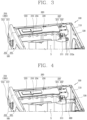
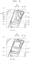
- the rear side of the storage unit 400 is first inserted into the rear end part 330 formed on the rear side of the drawer 300. Then, the front side of the storage unit 400 may be inserted into the front side of the drawer 300.
- detergent or softener may be accommodated in each of the storage containers 410 and 420. This results from the fact that detergent or softener is most frequently used to perform the clothes treating process.
- the storage unit 400 communicates with the dispenser assembly 200.
- the check valve 416, 426 provided on the rear side of the storage unit 400 communicate with the clothes treatment agent pump unit 220. Accordingly, the clothes treatment agent stored in the storage unit 400 may be supplied to the tub 170 via the drawer 300 by means of the clothes treatment agent pump unit 220.
- the first storage container 410 and the second storage container 420 each store the clothes treatment agent therein.
- the stored clothes treatment agent may be supplied to the tub 170 through the clothes treatment agent pump unit 220.
- the first storage container 410 and the second storage container 420 are located adjacent to each other in a state accommodated in the drawer 300.
- a predetermined space is defined inside each of the first storage container 410 and the second storage container 420.
- the clothes treatment agent is accommodated in each of the spaces.
- one of detergent and softener may be accommodated inside the first storage container 410 and another may be accommodated inside the second storage container 420.
- the detergent may be accommodated in the first storage container 410.
- the first storage container 410 is formed to have a larger volume than the second storage container 420. This results from the fact that a larger amount of detergent is required than softener during a general clothes treating process.
- the softener may be accommodated in the second storage container 420.
- the first storage container 410 and the second storage container 420 according to the exemplary embodiment of the present disclosure have the same or like structure and function to each other, except for the fact that the first storage container 410 and the second storage container 420 accommodate different types of clothes treatment agents and have partially different shapes.
- first storage container 410 and the second storage container 420 will be described together to avoid redundant description.
- the first storage container 410 and the second storage container 420 may be accommodated in a space defined in the drawer frame 320.
- the first storage container 410 is accommodated in a space formed in a left side of the drawer frame 320 (see FIG. 6 ).
- the second storage container 420 is accommodated in a space defined in a right side of the drawer frame 320.
- the first storage container 410 includes a first storage body portion 411, a first storage cover portion 412, a first detachment/attachment protrusion 413, a first storage cap portion 414, and a first through hole 415, a first check valve 416, a first sensor portion 417, and a first sealing portion 418.
- the second storage container 410 includes a second storage body portion 421, a second storage cover portion 422, a second detachment/attachment protrusion 423, a second storage cap portion 424, and a second through hole 425, a second check valve 426, a second sensor portion 427, and a second sealing portion 428.
- the storage body portions 411 and 421 define spaces in which the clothes treatment agent is accommodated.
- the storage body portions 411 and 421 extend in the lengthwise direction, namely, in the back and forth direction in the embodiment.
- the storage cover portions 412 and 422 are located on upper sides of the storage body portions 411 and 421.
- the storage body portions 411 and 421 and the storage cover portions 412 and 422 may be integrally formed with each other. That is, the storage body portions 411 and 421 and the storage cover portions 412 and 422 may be coupled so as not to be arbitrarily separated from each other.
- the detachment/attachment protrusions 413 and 423 protrude between the storage body portions 411 and 421 and the storage cover portions 412 and 422.
- the user can easily detach the storage containers 410 and 420 by gripping the detachment/attachment protrusions 413 and 423.
- the check valves 416 and 426 are provided on the rear sides of the storage body portions 411 and 421, respectively.
- the inner spaces of the storage body portions 411 and 421 may communicate with the clothes treatment agent pump unit 220 by the check valves 416 and 426.
- the storage body portions 411 and 421 are provided on the rear sides thereof with the sensor portions 417 and 427 and the sealing portions 418 and 428 configured to seal the sensor portions 417 and 427.
- Information related to a remaining amount of clothes treatment agents accommodated in the storage body portions 411 and 421 may be transmitted to a control unit (not illustrated) through the sensor portions 417 and 427.
- the storage body portions 411 and 421 extend in the lengthwise direction, namely, in the back and forth direction in the embodiment. Widths of the storage body portions 411 and 421 in the left and right direction in the embodiment may be different in the lengthwise direction.
- the another side of the storage body portion 411, 421, namely, the rear side in the embodiment, is formed to have a wider width than the still another side of the storage body portion 411, 421.
- the storage body portion 411, 421 is formed such that the width of the still another side is narrower than the widths of the one side and the another side.
- the housing accommodation part 350 may be located in a space defined as the still another sides of the storage containers 410 and 420 are spaced apart from each other.
- the housing accommodation part 350 is located between the still another sides of the storage containers 410 and 420. Accordingly, the storage containers 410 and 420 may be disposed to surround the housing accommodation part 350 at the outside of the housing accommodation part 350.
- each storage container 410 and 420 may be in contact with an outer side of the inner wall 323 extending in the lengthwise direction.
- Each of the storage cover portions 412 and 422 is located on one side of each of the storage body portions 411 and 421, namely, on the upper side in the embodiment.
- the storage cover portions 412 and 422 are configured to cover the storage body portions 411 and 421, respectively. That is, the storage cover portions 412 and 422 function as covers of the storage body portions 411 and 421.
- the storage cap portions 414 and 424 are provided on the front sides of the storage cover portions 412 and 422, respectively.
- the storage cap portions 414 and 424 are configured to seal openings (not illustrated) formed on the front sides of the storage cover parts 412 and 422, respectively.
- the storage cap portion 414, 424 can open the storage cap portion 414, 424 and supply the clothes treatment agent through the opening (not illustrated).
- the storage cap portions 414 and 424 may be configured to be coupled to or separated from the storage cover portions 412 and 422 in a rotating manner.
- the through holes 415 and 425 are formed in a penetrating manner at the front sides of the storage cap portions 414 and 424, respectively, on the storage cover portions 412 and 422.
- the through holes 415 and 425 allow inside and outside of the storage body portions 411 and 421 to communicate with each other, so as to maintain the balance of pressure inside the storage body portions 411 and 421.
- the through holes 415 and 425 communicate the inside and outside of the storage body portions 411 and 421, so as to balance the internal pressure of the storage body portions 411 and 421 and atmospheric pressure. Accordingly, the internal pressure of the storage body portions 411 and 421 can be maintained to be the same as the atmospheric pressure, despite the outflow of the clothes treatment agent.
- the through holes 415 and 425 may be located adjacent to each other. That is, the first through hole 415 may be located on one side of the first storage cover portion 412 adjacent to the second storage container 420. Likewise, the second through hole 425 may be located on one side of the second storage cover portion 422 adjacent to the first storage container 410.
- the storage unit 400 is configured such that the front side thereof where the through holes 415 and 425 are formed rises upward when the storage unit 400 is attached to or detached from the drawer 300. Accordingly, the clothes treatment agent is not discharged through the through holes 415 and 425. This will be described in detail later.
- the check valves 416 and 426 are configured to allow or block the communication between the inner spaces of the storage body portions 411 and 421 and the clothes treatment agent pump unit 220. By virtue of the communication, the clothes treatment agent accommodated in the inner spaces of the storage body portions 411 and 421 can be discharged to the outside.
- the check valves 416 and 426 are located on rear lower sides of the storage body portions 411 and 421, respectively.
- the check valves 416 and 426 protrude outward from the rear surfaces of the storage body portions 411 and 421, respectively, by a predetermined distance. This may result in that the storage containers 410 and 420 can be inserted into the space of the drawer 300 only from their rear sides.
- the primary pump valves 224 are insertedly coupled to the check valves 416 and 426, respectively. At this time, the primary pump valves 224 are in contact with the check valves 416 and 426 to push forward the check valves 416 and 426 by a predetermined distance.
- the intake ports 416d and 426d formed on the outer circumferences of the check valves 416 and 426 and the inlet ports 224d formed on the outer circumferences of the respective primary pump valves 224 communicate with the inner spaces of the storage body portions 411 and 421.
- each check valve 416 and 426 is moved to the rear side by the predetermined distance due to an elastic restored force. Accordingly, the inner spaces of the storage body portions 411 and 421 and the outside which have communicated with each other are blocked from each other.
- the clothes treatment agent does not leak through the check valves 416 and 426.
- the check valves 416 and 426 may be provided in any form that limits an arbitrary fluid to flow in only one direction and allows or restricts the flow of the fluid.
- the check valves 416 and 426 may be configured as lift check valves.
- the check valves 416 and 426 each include a check valve cylinder portion 416a, 426a, a check valve cap portion 416b, 426b, a check valve elastic portion 416c, 426c, and an intake port 416d, 426d (see FIG. 20 ).
- the check valve cylinder portion 416a, 426a forms the body of the check valve 416, 426.
- the check valve cylinder portion 416a, 426a is formed to extend in the lengthwise direction.
- the check valve cylinder portion 426a, 426a is formed in a cylindrical shape which has a circular cross section and extends in the lengthwise direction.
- a space portion is defined inside the check valve cylinder portion 416a, 426a.
- the space portion extends from one end to another end of the check valve cylinder portion 416a, 426a in the lengthwise direction.
- the space portion is formed through the check valve cylinder portion 416a, 426a in the lengthwise direction.
- the space portion may allow the inner space of the storage body portion 411, 421 to communicate with the inner space of the primary valve cylinder portion 224a through the intake port 416d, 426d.
- the space portion is formed to have a diameter equal to or larger than a diameter of the primary valve cylinder portion 224a.
- the primary valve cylinder portion 224a is inserted into one side of the space portion in the lengthwise direction, namely, into the rear side in the embodiment.
- the primary valve cylinder portion 224a may be moved in the lengthwise direction, namely, in the back and forth direction in the embodiment, in the state inserted in the space portion.
- a through hole is formed through the front side of the check valve cylinder portion 416a, 426a.
- One side of the check valve cap portion 416b, 426b, namely, the front end portion thereof in the embodiment is inserted into the through hole.
- the inner space of the storage body portion 411, 421 and the inner space of the check valve cylinder portion 416a, 426a may communicate with the inner space pf the primary valve cylinder portion 224a.
- the clothes treatment agent accommodated in the storage body portion 411, 421 may flow into the inner space of the primary valve cylinder portion 224a by the communication.
- the check valve 416, 426 communicates with the clothes treatment agent pump unit 220 when the storage unit 400 is inserted into the drawer 300.
- the clothes treatment agent accommodated in the storage unit 400 can be introduced into the clothes treatment agent pump unit 220.
- the clothes treatment agent may remain in a portion where the check valve 416, 426 communicates with the clothes treatment agent pump unit 220. At this time, if the sensor portion 417, 427 is located below the check valve 416, 426, the remaining clothes treatment agent may be leaked and brought into contact with the sensor portion 417, 427. In this case, the sensor portion 417, 427 may be contaminated or damaged.
- the sensor portion 417, 427 according to the embodiment of the present disclosure is located above the check valve 416, 426, thereby fundamentally preventing an occurrence of such a situation.
- the sensor portion 417, 427 may include a plurality of terminals (not illustrated) on one side wall of the storage body portion 411, 421, namely, on a rear wall in the embodiment.
- the plurality of terminals (not illustrated) may be located at different heights to sense a surface of the clothes treatment agent accommodated inside the storage body portion 411, 421.
- the sensor portion 417, 427 includes three terminal spaces. This is because three terminals (not illustrated) are provided. The number of terminal spaces provided in the sensor portion 417, 427 may change depending on the number of terminals (not illustrated).
- the sensor portion 417, 427 is electrically connected to an external control unit (not illustrated). Information related to a remaining amount of clothes treatment agents detected by the sensor portion 417, 427 may be transmitted to the control unit (not illustrated). To this end, a plurality of connectors (not illustrated) may be electrically connected to the sensor portion 417, 427.
- An opening may be formed through one side of the sealing portion 418, 428 facing the sensor portion 417, 427.
- the sensor portion 417, 427 may be electrically connected to the external control unit (not illustrated) through the opening.
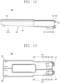
- the third bottom surface 433 may extend away from the first bottom surface 431, namely, to the rear side in the embodiment at a predetermined inclination with respect to the first bottom surface 431. In one embodiment, the third bottom surface 433 may extend horizontally.
- the third bottom surface 433 is located lower than the first bottom surface 431. That is, the longest distance D1 between the first bottom surface 431 and the storage cover portion 412, 422 is shorter than the shortest distance D3 between the third bottom surface 433 and the storage cover portion 412, 422.
- the third bottom surface 433 is located higher than the second bottom surface 432. That is, the shortest distance D2 between the second bottom surface 432 and the storage cover portion 412, 422 is longer than a longest distance D3' between the third bottom surface 433 and the storage cover portion 412, 422.
- the first bottom surface 431 and the third bottom surface 434 may be continuously connected to each other by the first joint surface 434.
- the first joint surface 434 extends from one side of the first bottom surface 431, namely, from a rear end in the embodiment, to one side of the third bottom surface 433, namely, to a front end in the embodiment.
- the first joint surface 434 may extend at a predetermined angle with respect to the first bottom surface 431. In one embodiment, the first joint surface 434 may extend so that a distance up to the storage cover portion 412, 422 is increased as it is farther away from the first bottom surface 431.
- the second joint surface 434 may extend at a predetermined angle with respect to the third bottom surface 433.
- the first joint surface 434 may extend so that a distance up to the storage cover portion 412, 422 is decreased as it is farther away from the third bottom surface 433.
- the first joint surface 434 may be formed to be downwardly or forwardly convex to have a cross section in a curved shape.
- the first joint surface 434 is preferably formed to be inclined from the front side to the rear side, so that the clothes treatment agent does not stay. That is, the front end of the first joint surface 434 connected to the first bottom surface 431 is preferably higher in height than the rear end of the first joint surface 434 connected to the third bottom surface 433.
- the clothes treatment agent flowing along the first bottom surface 431 may flow toward the third bottom surface 433 via the first joint surface 434.
- a space partially surrounded by the third bottom surface 433 may be defined as the second collection space portion 437.
- the definition may extend so that the second collection space portion 437 may also be defined as a space partially surrounded by the third bottom surface 433 and the first joint surface 434.
- the second bottom surface 432 and the third bottom surface 435 may be continuously connected to each other by the second joint surface 435.
- the second joint surface 435 extends from one side of the third bottom surface 433, namely, from a rear end in the embodiment, to one side of the second bottom surface 432, namely, to a front end in the embodiment.
- the second joint surface 435 may extend at a predetermined angle with respect to the third bottom surface 433. In one embodiment, the second joint surface 435 may extend so that a distance up to the storage cover portion 412, 422 is increased as it is farther away from the third bottom surface 433.
- the second joint surface 435 may extend at a predetermined angle with respect to the second bottom surface 432. In one embodiment, the second joint surface 435 may extend so that a distance up to the storage cover portion 412, 422 is increased as it is farther away from the second bottom surface 432.
- the second joint surface 435 is preferably formed to be inclined from the front side to the rear side, so that the clothes treatment agent does not stay. That is, the front end of the second joint surface 435 connected to the third bottom surface 433 is preferably higher in height than the rear end of the second joint surface 435 connected to the second bottom surface 432.
- the clothes treatment agent flowing along the first bottom surface 431 and the third bottom surface 433 may flow toward the third bottom surface 433 via the second joint surface 435.
- a space partially surrounded by the second bottom surface 432 may be defined as the first collection space portion 436.
- the definition may extend so that the first collection space portion 436 may also be defined as a space partially surrounded by the second bottom surface 432 and the second joint surface 435.
- the first collection space portion 436 is a space where the clothes treatment agent flowing along the first bottom surface 431 and the third bottom surface 433 is finally collected.
- the first collection space portion 436 may also be defined as a space partially surrounded by the second joint surface 435. That is, the first collection space portion 436 is a space formed on one side of the second joint surface 435 facing the storage cover portion 412, 422, namely, on the upper side in the embodiment.
- the first collection space portion 436 communicates with a space partially surrounded by the first bottom surface 431, the third bottom surface 433, and the first joint surface 434.
- the clothes treatment agent accommodated in the storage container 410, 420 flows toward the first collection space portion 436 along the first bottom surface 431, the first joint surface 434, and the third bottom surface 433.
- the check valve 416, 426 is located in the first collection space portion 436. Specifically, one end portion of the check valve 416, 426 in the lengthwise direction is located in the first collection space portion 436.
- the intake port 416d, 426d of the check valve 416, 426 is located in the first collection space portion 436.
- the first collection space portion 436 and the inner space of the check valve cylinder portion 416a, 426a may communicate with each other.
- the second collection space portion 437 is a space in which the clothes treatment agent flowing along the second bottom surface 432 is primarily collected.
- the second collection space portion 437 may also be defined as a space partially surrounded by the first joint surface 434. That is, the second collection space portion 436 is a space formed on one side of the first joint surface 434 facing the storage cover portion 412, 422, namely, on the upper side in the embodiment.
- the clothes treatment agent accommodated in the storage container 410, 420 can flow to the second collection space portion 437 along the first bottom surface 431.
- the clothes treatment agent introduced into the second collection space portion 437 can flow toward the first collection space portion 436.
- the third bottom surface 433 may not be provided in the discharge inclined portion 430. That is, the first bottom surface 431 and the second bottom surface 432 may be directly connected to each other. The first bottom surface 431 and the second bottom surface 434 may be connected to each other by the first joint surface 434 in an inclined manner.
- the clothes treatment agent accommodated in the storage container 410, 420 can flow along the first bottom surface 431 and the first joint surface 434 so as to be introduced into the first collection space portion 436.
- the clothes treatment agent housing 500 may be detachably accommodated in the housing accommodation part 350 of the drawer 300.
- a predetermined space is defined inside the clothes treatment agent housing 500.
- the supplied clothes treatment agent or fluid may stay in the predetermined space.
- an amount of clothes treatment agents or fluids staying in the predetermined space exceeds a predetermined reference value, the clothes treatment agent or fluid may be discharged to the outside through a discharge passage 580.
- the clothes treatment agent housing 500 is formed such that a length in the back and forth direction (i.e., the lengthwise direction) is longer than a width in the left and right direction in the embodiment.
- the shape of the clothes treatment agent housing 500 may change depending on the shape of the housing accommodation part 350.
- the clothes treatment agent housing 500 includes an outer circumferential surface 510, an opening 520, a spacing protrusion 530, a siphon portion 540, a siphon cover portion 550, a siphon coupling portion 560, and a collecting portion 570, and a discharge passage 580.
- the outer circumferential surface 510 defines an outer surface of the clothes treatment agent housing 500.
- the outer circumferential surface 510 includes a first part 510a extending by a predetermined distance to be inclined in a direction from the front side to the rear side of the clothes treatment agent housing 500, a second part 510b extending rearward from the first part 510a at a predetermined angle with respect to the first part 510a, and a third part 510c extending upward from the second part 510b at a predetermined angle with respect to the second part 510b.
- the outer circumferential surface 510 may be formed in a downwardly-concave shape by the first to third parts 510a, 510b, and 510c.
- the support protrusion surface 511 is seated on the support rod 352. Therefore, the front side of the clothes treatment agent housing 500 can be stably supported in a state of being spaced apart from the lower surface 351 by a predetermined distance.
- the opening 520 communicates with the inner space of the clothes treatment agent housing 500.
- the clothes treatment agent or fluid supplied through the opening 520 may flow to the collecting portion 554 via the inner space of the clothes treatment agent housing 500.
- the clothes treatment agent or fluid collected in the collecting portion 554 may be discharged through the discharge passage 580 via the siphon portion 540.
- the spacing protrusion 530 is provided so that one side of the inner wall 323 surrounding the housing accommodation part 350 is spaced a predetermined distance apart from the clothes treatment agent housing 500. Specifically, the spacing protrusion 530 allows the inner wall 323 of the rear side in the embodiment to be spaced the predetermined distance apart from the rear side of the clothes treatment agent housing 500.
- the spacing protrusion 530 may be provided in plurality.
- the spacing protrusion 530 is provided by two, which are spaced apart from each other by a predetermined distance.
- the number and spaced distance of the spacing protrusions 530 may change depending on the number and spaced distance of the protruding portions 355.
- the spacing protrusion 530 may be formed in a plate shape having a small thickness relative to a width or length. Accordingly, a space occupied by the spacing protrusion 530 in the space portion 356 in the widthwise direction, namely, in the left and right direction in the embodiment, can be minimized.
- the second spacing surface 532 comes in contact with at least part of the first surface 355a of the protruding portion 355.
- the siphon portion 540 is located in the inner space of the clothes treatment agent housing 500. In the embodiment, the siphon portion 540 is located between the second part 510b and the third part 510c. In addition, a lower end portion of the siphon portion 540 is located on the discharge passage 580.
- the siphon cover portion 550 is configured to shield the upper side of the siphon portion 540.
- the siphon cover portion 550 may be configured to seal an upper opening of the hollow portion formed in the siphon portion 540. Accordingly, the fluid or clothes treatment agent does not flow into the hollow portion inside the siphon portion 540 through the upper opening.
- the first part 510a and the second part 510b of the outer circumferential surface 510 are formed to be inclined downward from the front side of the siphon portion 540.
- the third part 510c of the outer circumferential surface 510 is formed to be inclined downward from the rear side of the siphon portion 540.
- the collecting portion 570 communicates with the siphon portion 540.
- the clothes treatment agent or fluid collected in the collecting portion 570 may flow to the discharge passage 580 by the siphon portion 540.
- the discharge passage 580 communicates with the siphon portion 540.
- the clothes treatment agent or fluid collected in the collecting portion 570 is discharged through the discharge passage 580 via the hollow portion formed through the inside of the siphon portion 540.
- the support member 600 is configured to support the dispenser assembly 200 at the rear side.
- the support member 600 may be coupled to the rear protrusion 212 of the dispenser assembly 200.
- the support member 600 is coupled through the rear surface 130 of the housing 100. After the support member 600 is inserted through the rear surface 130, it may be rotated to be coupled to the rear surface 130 (see FIG. 4 ).
- the dispenser assembly 200 can be stably supported by the support member 600.
- the support member 600 includes a support body portion 610, a support hollow portion 620, a support rib portion 630, and a support head portion 640.
- the support body portion 610 defines the body of the support member 600.
- the support body portion 610 extends by a predetermined distance in the lengthwise direction.
- the support body portion 610 is formed to have a circular cross section. That is, the support body portion 610 has a cylindrical shape.
- the shape of the support body 610 may change to a polygonal column, an elliptical column, or the like.
- the support body portion 610 is rotatably coupled through the support member insertion hole 131 of the rear surface 130.
- the support body portion 610 includes a first body part 611 and a second body part 612.
- the sum of extended distances of the first body part 611 and the second body part 612 is preferably equal to or greater than the sum of a distance between one end of the rear protrusion 212 and the rear surface 130 and a protruded length of the rear protrusion 212.
- the first body part 611 defines a body of one side of the support body portion 610 in the lengthwise direction.
- the support hollow portion 620 is formed inside the first body portion 611 in a penetrating manner.
- the rear protrusion 212 of the frame unit 210 may be inserted into the support hollow portion 620.
- the second body part 612 defines a body of another side of the support body portion in the lengthwise direction.
- the second body part 612 extends by a predetermined distance from one end of the first body part 611 facing the support head portion 640, namely, from the rear end in the embodiment.
- the support rib portion 630 is formed on an outer circumference of the second body part 612.
- the support head portion 640 is coupled to one end of the second body portion 612 opposite to the first body part 611.
- the rear protrusion 212 is inserted into the support hollow portion 620.
- An opening is formed on one side of the support hollow portion 620, namely, on one side opposite to the support head portion 640 in the embodiment in a manner of being recessed by a predetermined distance.
- the rear protrusion 212 may be inserted into the support hollow portion 620 through the opening.
- the support hollow portion 620 is formed by being recessed in the lengthwise direction into one end portion of the first body part 611 facing the rear protrusion 212 by a predetermined distance.
- the support hollow portion 620 extends within the first body part 611 by the predetermined distance in the lengthwise direction.
- the support hollow portion 620 is a portion recessed by the predetermined distance in the lengthwise direction into the one end portion of the first body part 611 opposite to the support head portion 640.
- the shape and extended distance of the support hollow portion 620 may be determined to correspond to the shape and protruded length of the rear protrusion 212.
- the support rib portion 630 is configured to reinforce rigidity of the support body portion 610. In addition, the support rib portion 630 is configured to reduce an overall weight of the support body portion 610.
- the support rib portion 630 is formed on the outer circumference of the second body part 612.
- the support rib portion 630 may be provided in plurality formed on the outer circumference of the second body part 612 in a circumferential direction.
- the support rib portion 630 may extend in the lengthwise direction. In the embodiment, the support rib portion 630 extends by a predetermined distance in the lengthwise direction of the second body part 612.
- the support rib portion 630 may be formed in a plate-like shape. That is, the support rib portion 630 may be narrow in width in the left and right direction, high in height in the up and down direction, and long in length in the back and forth direction.
- Support space portions 631 are formed at both sides of the support rib portion 630 in a direction perpendicular to the lengthwise direction of the support rib portion 630, namely, at right and left sides in the embodiment.
- the support space portion 631 is recessed by a predetermined distance into the outer circumference of the second body part 612.
- the support space portion 631 may be provided in plurality.
- the plurality of support space portions 631 may be spaced apart from one another by predetermined distances.
- the support rib portion 630 is located between the support space portions 631 adjacent to each other. In other words, it may be said that the support rib portion 630 partitions the support space portions 631.
- the support space portion 631 may extend in the lengthwise direction. In the embodiment, the support space portion 631 extends by a predetermined distance in the lengthwise direction of the second body part 612.
- the support hollow portion 620 is formed through the inside of the first body part 611 in the lengthwise direction. That is, the support hollow portion 620 and the support space portion 631 are not in communication with each other.
- the support head portion 640 is a portion that is gripped by the user to couple the support member 600 to the rear surface 130 after inserting the support member 600 through the rear surface 130.
- the support head portion 640 is located on one end of the second body part 612 opposite to the first body part 611.
- the support head portion 640 is formed in a circular plate shape.
- the shape of the support head portion 640 may change to any shape that the user can grip.
- the support head portion 640 includes a coupling protrusion 641, a direction indicating groove 642, a guide protrusion 643, and a grip protrusion 644.
- the coupling protrusion 641 is a portion where the support member 600 inserted through the support member insertion hole 131 is coupled to the rear surface 130.
- the coupling protrusion 641 may be coupled to the support member coupling portion 132a as the support member 600 is rotated.
- the coupling protrusion 641 is provided in plurality radially on an inner side of one surface of the support head portion 640 facing the support body portion 610 in a circumferential direction.
- the plurality of coupling protrusions 641 are spaced apart from one another by predetermined distances.
- the coupling protrusion 641 is provided by three, but the number may vary.
- the second protrusion 641b may also be rotated so as to be coupled to the support member coupling portion 132a.
- the second protrusion 641b may also be rotated so as to be released from the support member coupling portion 132a.
- the direction indicating groove 642 may be formed through the support head portion 640.
- the direction indicating groove 642 may be formed to surround the guide protrusion 643.
- the user can recognize the rotating direction of the support member 600 and can easily manipulate the support member 600.
- the guide protrusion 643 is provided in plurality on a radially inner side of the one surface of the support body portion 640 in the circumferential direction.
- the plurality of guide protrusions 643 are spaced apart from one another by predetermined distances.
- the guide protrusion 643 is provided by three, but the number may vary.
- the grip protrusion 644 extends in a radial direction of the support head portion 640.
- the grip protrusion 644 may be formed in any shape that the user can grip.
- FIG. 18 illustrates a rear side of the drawer frame 320 in a state in which the storage unit 400 has been accommodated.
- the check valve 416, 426 is provided on the rear lower side of the storage unit.
- the check valve 416, 426 protrudes by a predetermined distance.
- the check valve 416, 426 located in the check valve opening 332a cannot pass through the sensor opening 332b due to the partition member 331.
- the rear side of the storage unit 400 where the check valve 416, 426 is located cannot be inserted later or separated earlier than the front side.
- the rear side of the storage unit 400 should be inserted first.
- the rear side of the storage unit 400 should be separated later.
- the check valve 416, 426 passing through the upper sensor opening 332b is stopped by the partition member 331.
- the check valve 416, 426 passing through the upper sensor opening 332b is stopped by the partition member 331.
- the rear side of the storage unit 400 should first be inserted into the drawer 300 while maintaining a state in which the upper side of the storage unit 400 is located higher than the rear side of the storage unit 400.
- the storage unit 400 is inserted into the space of the drawer frame 320 in a state where a distance between one side of the storage unit 400 in the lengthwise direction on which the check valve 416, 426 is located, namely, the rear side of the storage unit 400 in the embodiment, and one side of the drawer frame 320 on which the rear end part 330 is located, namely, the rear side of the drawer frame 320 in the embodiment, is shorter than a distance between another side of the storage unit 400 in the lengthwise direction, namely, the front side of the storage unit 400 in the embodiment, and another side of the drawer frame 320 in the lengthwise direction, namely, the front side of the drawer frame 320 in the embodiment.
- the storage unit 400 is inserted into the space of the drawer frame 320 in a state in which the another side of the storage unit 400 in the lengthwise direction, namely, the front side of the storage unit 400 in the embodiment, is spaced farther apart from the drawer frame 320 than the one side of the storage unit 400 in the lengthwise direction having the check valve 416, 426, namely, the rear side of the storage unit 400 in the embodiment.
- the storage unit 400 is inserted into the space of the drawer frame 320 in a manner that one surface in the lengthwise direction, namely, a lower surface in the embodiment, forms an acute angle with the bottom portion 324 formed on one surface of the drawer frame 320, namely, on the lower side in the embodiment, at a vertex which corresponds to one side of the storage unit 400 where the check valve 416, 426 is located.
- the leakage of the clothes treatment agent through the through hole 415, 425 formed on the front side of the storage unit 400 can be prevented during the process of inserting the storage unit 400 into the drawer 300.
- the rear side of the storage unit 400 should first be detached from the drawer 300 while maintaining a state in which the upper side of the storage unit 400 is located higher than the lower side of the storage unit 400.
- the residual of the clothes treatment agent accommodated in the storage unit 400 can be minimized.
- the rear side of the housing accommodation part 350 is spaced apart from the second plane portion, which is located at the rear, of the second plane portions of the inner wall 323 by the protruded distance of the protruding portion 355 and the protruded distance of the spacing protrusion 530.
- the overflowed clothes treatment agent or fluid can all be discharged to the tub 170 (refer to dotted arrows in FIGS. 21 to 23 ). Accordingly, the overflowed clothes treatment agent or fluid does not remain in the inner space of the drawer 300.
- the support member insertion hole 131 is formed through the rear surface 130.
- the support body portion 610 of the support member 600 is coupled through the support member insertion hole 131.
- the support member coupling hole 132 and the support member guide hole 133 may each be formed in an arcuate shape.
- the plurality of support member coupling holes 132 and support member guide holes 133 may be alternately arranged along the circumferential direction.
- FIG. 25 a state in which the support member 600 is inserted into the rear surface 130 through the process is illustrated.
- one end of the rear protrusion 212 may be spaced a predetermined distance apart from one end of the support hollow portion 620 facing the second body portion 612, namely, from a boundary between the first body portion 611 and the second body portion 612.
- the coupling protrusion 641 When the coupling protrusion 641 is coupled to the support member coupling portion 132a, the rotation of the support member 600 is terminated.
- the coupling protrusion 641 and the support member coupling portion 132a may be fitted to each other in a snapping manner.
Landscapes
- Engineering & Computer Science (AREA)
- Textile Engineering (AREA)
- Detail Structures Of Washing Machines And Dryers (AREA)
- Packaging Of Annular Or Rod-Shaped Articles, Wearing Apparel, Cassettes, Or The Like (AREA)
Applications Claiming Priority (3)
| Application Number | Priority Date | Filing Date | Title |
|---|---|---|---|
| KR20190106712 | 2019-08-29 | ||
| KR1020200018600A KR102906783B1 (ko) | 2019-08-29 | 2020-02-14 | 드로워 및 이를 포함하는 의류 처리 장치 |
| EP20191975.0A EP3786340B1 (fr) | 2019-08-29 | 2020-08-20 | Tiroir |
Related Parent Applications (2)
| Application Number | Title | Priority Date | Filing Date |
|---|---|---|---|
| EP20191975.0A Division EP3786340B1 (fr) | 2019-08-29 | 2020-08-20 | Tiroir |
| EP20191975.0A Division-Into EP3786340B1 (fr) | 2019-08-29 | 2020-08-20 | Tiroir |
Publications (2)
| Publication Number | Publication Date |
|---|---|
| EP4397801A2 true EP4397801A2 (fr) | 2024-07-10 |
| EP4397801A3 EP4397801A3 (fr) | 2024-08-14 |
Family
ID=72178451
Family Applications (2)
| Application Number | Title | Priority Date | Filing Date |
|---|---|---|---|
| EP20191975.0A Active EP3786340B1 (fr) | 2019-08-29 | 2020-08-20 | Tiroir |
| EP24171519.2A Pending EP4397801A3 (fr) | 2019-08-29 | 2020-08-20 | Tiroir |
Family Applications Before (1)
| Application Number | Title | Priority Date | Filing Date |
|---|---|---|---|
| EP20191975.0A Active EP3786340B1 (fr) | 2019-08-29 | 2020-08-20 | Tiroir |
Country Status (4)
| Country | Link |
|---|---|
| US (1) | US11739468B2 (fr) |
| EP (2) | EP3786340B1 (fr) |
| CN (1) | CN112442861B (fr) |
| AU (1) | AU2020223722B2 (fr) |
Families Citing this family (3)
| Publication number | Priority date | Publication date | Assignee | Title |
|---|---|---|---|---|
| WO2022237470A1 (fr) * | 2021-05-10 | 2022-11-17 | 青岛海尔滚筒洗衣机有限公司 | Boîte de stockage de liquide, appareil de distribution d'additif et procédé d'identification |
| WO2023286358A1 (fr) * | 2021-07-12 | 2023-01-19 | 日立グローバルライフソリューションズ株式会社 | Lave-linge |
| SI26564A (sl) | 2023-11-16 | 2025-05-30 | Gorenje Gospodinjski Aparati, D.O.O. | Pralni stroj z avtomatskim dozirnim sistemom |
Citations (2)
| Publication number | Priority date | Publication date | Assignee | Title |
|---|---|---|---|---|
| KR100781247B1 (ko) | 2001-07-06 | 2007-11-30 | 엘지전자 주식회사 | 세탁기의 액체세제 자동 투입장치 |
| KR20160087823A (ko) | 2013-11-25 | 2016-07-22 | 하이어 그룹 코포레이션 | 세제자동투입 세탁기 및 방법 |
Family Cites Families (23)
| Publication number | Priority date | Publication date | Assignee | Title |
|---|---|---|---|---|
| KR101444356B1 (ko) | 2007-03-31 | 2014-09-24 | 엘지전자 주식회사 | 세탁기 |
| KR101386712B1 (ko) | 2007-04-02 | 2014-04-18 | 엘지전자 주식회사 | 세탁기 |
| EP2003237B1 (fr) | 2007-06-12 | 2016-05-04 | Electrolux Home Products Corporation N.V. | Distributeur de produits détergents pour un lave-linge |
| KR101482108B1 (ko) * | 2008-05-23 | 2015-01-13 | 엘지전자 주식회사 | 세탁기 |
| US20100000264A1 (en) * | 2008-07-01 | 2010-01-07 | Whirlpool Corporation | Method for converting a household cleaning appliance with a non-bulk dispensing system to a household cleaning appliance with a bulk dispensing system |
| IT1391855B1 (it) | 2008-09-04 | 2012-01-27 | Indesit Co Spa | Metodo e dispositivo per convogliare agenti di lavaggio in una vasca di una macchina di lavaggio |
| US8931667B2 (en) * | 2008-09-24 | 2015-01-13 | The Procter & Gamble Company | Methods and apparatuses for dispensing fluids |
| US20100161143A1 (en) * | 2008-12-18 | 2010-06-24 | Christopher Lawrence Smith | Dispensing system |
| EP2251480B1 (fr) | 2009-05-11 | 2017-11-29 | Electrolux Home Products Corporation N.V. | Machine à laver |
| EP3460120B1 (fr) | 2009-05-11 | 2023-07-12 | Electrolux Home Products Corporation N.V. | Machine à laver |
| DE102009028062B4 (de) | 2009-07-29 | 2014-08-28 | BSH Bosch und Siemens Hausgeräte GmbH | Wasserführendes Haushaltsgerät |
| CN203334043U (zh) * | 2013-07-01 | 2013-12-11 | 惠而浦(中国)投资有限公司 | 洗衣机用自动投放洗涤剂系统 |
| WO2015002413A1 (fr) * | 2013-07-03 | 2015-01-08 | 삼성전자주식회사 | Dispositif d'alimentation en détergent et machine à laver dotée de celui-ci |
| WO2015080491A2 (fr) | 2013-11-28 | 2015-06-04 | Lg Electronics Inc. | Machine à laver |
| DE102013225111B3 (de) | 2013-12-06 | 2015-01-08 | BSH Bosch und Siemens Hausgeräte GmbH | Dosiereinrichtung für eine Waschmaschine |
| WO2015133796A1 (fr) | 2014-03-04 | 2015-09-11 | Lg Electronics Inc. | Lave-linge |
| EP3486365B1 (fr) * | 2014-12-23 | 2020-09-09 | Electrolux Appliances Aktiebolag | Lave-linge comportant un dispositif de dosage automatique |
| CN106319871B (zh) * | 2015-06-15 | 2018-08-07 | 杭州神林电子有限公司 | 一种能投放洗涤剂的进水盒 |
| CN108729142B (zh) | 2017-04-17 | 2020-08-14 | 青岛海尔滚筒洗衣机有限公司 | 一种洗衣机分配盒 |
| CN109423840B (zh) | 2017-08-22 | 2022-02-01 | 青岛海尔洗涤电器有限公司 | 一种洗涤添加剂盒及洗衣机 |
| US10876245B2 (en) * | 2018-05-30 | 2020-12-29 | Haier Us Appliance Solutions, Inc. | Washing machine appliance with a smart additive bulk dispensing assembly |
| CN209307679U (zh) | 2018-12-14 | 2019-08-27 | 浙江宏昌电器科技股份有限公司 | 一种具有溶液储量检测功能的投放装置 |
| CN110004669B (zh) * | 2019-04-04 | 2024-10-01 | 佛山市云米电器科技有限公司 | 一种洗衣机的自动投放系统 |
-
2020
- 2020-08-20 EP EP20191975.0A patent/EP3786340B1/fr active Active
- 2020-08-20 EP EP24171519.2A patent/EP4397801A3/fr active Pending
- 2020-08-27 AU AU2020223722A patent/AU2020223722B2/en active Active
- 2020-08-28 US US17/006,509 patent/US11739468B2/en active Active
- 2020-08-31 CN CN202010898036.1A patent/CN112442861B/zh active Active
Patent Citations (2)
| Publication number | Priority date | Publication date | Assignee | Title |
|---|---|---|---|---|
| KR100781247B1 (ko) | 2001-07-06 | 2007-11-30 | 엘지전자 주식회사 | 세탁기의 액체세제 자동 투입장치 |
| KR20160087823A (ko) | 2013-11-25 | 2016-07-22 | 하이어 그룹 코포레이션 | 세제자동투입 세탁기 및 방법 |
Also Published As
| Publication number | Publication date |
|---|---|
| CN112442861B (zh) | 2023-10-17 |
| EP3786340A1 (fr) | 2021-03-03 |
| AU2020223722B2 (en) | 2022-04-07 |
| CN112442861A (zh) | 2021-03-05 |
| US20210062394A1 (en) | 2021-03-04 |
| AU2020223722A1 (en) | 2021-03-18 |
| EP3786340B1 (fr) | 2024-06-05 |
| EP4397801A3 (fr) | 2024-08-14 |
| US11739468B2 (en) | 2023-08-29 |
Similar Documents
| Publication | Publication Date | Title |
|---|---|---|
| EP3786338B1 (fr) | Conteneur de stockage et machine de traitement de vêtements le comprenant | |
| EP3786340B1 (fr) | Tiroir | |
| US12392076B2 (en) | Drawer and clothes treating machine including the same | |
| KR20170135237A (ko) | 의류처리장치 | |
| EP3786336B1 (fr) | Dispositif d'alimentation en détergent | |
| EP3786337B1 (fr) | Machine de traitement de linge | |
| RU2744859C1 (ru) | Выдвижной ящик и машина для обработки одежды, содержащая такой выдвижной ящик | |
| JP7522570B2 (ja) | 衣類処理装置 | |
| RU2744802C1 (ru) | Выдвижной ящик и машина для обработки одежды, содержащая такой выдвижной ящик |
Legal Events
| Date | Code | Title | Description |
|---|---|---|---|
| PUAI | Public reference made under article 153(3) epc to a published international application that has entered the european phase |
Free format text: ORIGINAL CODE: 0009012 |
|
| STAA | Information on the status of an ep patent application or granted ep patent |
Free format text: STATUS: THE APPLICATION HAS BEEN PUBLISHED |
|
| AC | Divisional application: reference to earlier application |
Ref document number: 3786340 Country of ref document: EP Kind code of ref document: P |
|
| AK | Designated contracting states |
Kind code of ref document: A2 Designated state(s): AL AT BE BG CH CY CZ DE DK EE ES FI FR GB GR HR HU IE IS IT LI LT LU LV MC MK MT NL NO PL PT RO RS SE SI SK SM TR |
|
| PUAL | Search report despatched |
Free format text: ORIGINAL CODE: 0009013 |
|
| AK | Designated contracting states |
Kind code of ref document: A3 Designated state(s): AL AT BE BG CH CY CZ DE DK EE ES FI FR GB GR HR HU IE IS IT LI LT LU LV MC MK MT NL NO PL PT RO RS SE SI SK SM TR |
|
| RIC1 | Information provided on ipc code assigned before grant |
Ipc: D06F 39/02 20060101AFI20240710BHEP |
|
| STAA | Information on the status of an ep patent application or granted ep patent |
Free format text: STATUS: REQUEST FOR EXAMINATION WAS MADE |
|
| 17P | Request for examination filed |
Effective date: 20241004 |
|
| RBV | Designated contracting states (corrected) |
Designated state(s): AL AT BE BG CH CY CZ DE DK EE ES FI FR GB GR HR HU IE IS IT LI LT LU LV MC MK MT NL NO PL PT RO RS SE SI SK SM TR |
|
| GRAP | Despatch of communication of intention to grant a patent |
Free format text: ORIGINAL CODE: EPIDOSNIGR1 |
|
| STAA | Information on the status of an ep patent application or granted ep patent |
Free format text: STATUS: GRANT OF PATENT IS INTENDED |
|
| INTG | Intention to grant announced |
Effective date: 20251210 |
|
| GRAJ | Information related to disapproval of communication of intention to grant by the applicant or resumption of examination proceedings by the epo deleted |
Free format text: ORIGINAL CODE: EPIDOSDIGR1 |
|
| STAA | Information on the status of an ep patent application or granted ep patent |
Free format text: STATUS: REQUEST FOR EXAMINATION WAS MADE |
|
| GRAP | Despatch of communication of intention to grant a patent |
Free format text: ORIGINAL CODE: EPIDOSNIGR1 |
|
| STAA | Information on the status of an ep patent application or granted ep patent |
Free format text: STATUS: GRANT OF PATENT IS INTENDED |
|
| GRAS | Grant fee paid |
Free format text: ORIGINAL CODE: EPIDOSNIGR3 |
|
| INTC | Intention to grant announced (deleted) | ||
| GRAA | (expected) grant |
Free format text: ORIGINAL CODE: 0009210 |
|
| STAA | Information on the status of an ep patent application or granted ep patent |
Free format text: STATUS: THE PATENT HAS BEEN GRANTED |