EP4397860A2 - Hydraulisches pumpensystem - Google Patents
Hydraulisches pumpensystem Download PDFInfo
- Publication number
- EP4397860A2 EP4397860A2 EP24175974.5A EP24175974A EP4397860A2 EP 4397860 A2 EP4397860 A2 EP 4397860A2 EP 24175974 A EP24175974 A EP 24175974A EP 4397860 A2 EP4397860 A2 EP 4397860A2
- Authority
- EP
- European Patent Office
- Prior art keywords
- pump
- hydraulic
- housing
- optionally
- tank
- Prior art date
- Legal status (The legal status is an assumption and is not a legal conclusion. Google has not performed a legal analysis and makes no representation as to the accuracy of the status listed.)
- Granted
Links
Images



Classifications
-
- E—FIXED CONSTRUCTIONS
- E02—HYDRAULIC ENGINEERING; FOUNDATIONS; SOIL SHIFTING
- E02F—DREDGING; SOIL-SHIFTING
- E02F9/00—Component parts of dredgers or soil-shifting machines, not restricted to one of the kinds covered by groups E02F3/00 - E02F7/00
- E02F9/20—Drives; Control devices
- E02F9/22—Hydraulic or pneumatic drives
- E02F9/2221—Control of flow rate; Load sensing arrangements
- E02F9/2232—Control of flow rate; Load sensing arrangements using one or more variable displacement pumps
-
- F—MECHANICAL ENGINEERING; LIGHTING; HEATING; WEAPONS; BLASTING
- F04—POSITIVE - DISPLACEMENT MACHINES FOR LIQUIDS; PUMPS FOR LIQUIDS OR ELASTIC FLUIDS
- F04B—POSITIVE-DISPLACEMENT MACHINES FOR LIQUIDS; PUMPS
- F04B23/00—Pumping installations or systems
- F04B23/02—Pumping installations or systems having reservoirs
- F04B23/021—Pumping installations or systems having reservoirs the pump being immersed in the reservoir
-
- F—MECHANICAL ENGINEERING; LIGHTING; HEATING; WEAPONS; BLASTING
- F15—FLUID-PRESSURE ACTUATORS; HYDRAULICS OR PNEUMATICS IN GENERAL
- F15B—SYSTEMS ACTING BY MEANS OF FLUIDS IN GENERAL; FLUID-PRESSURE ACTUATORS, e.g. SERVOMOTORS; DETAILS OF FLUID-PRESSURE SYSTEMS, NOT OTHERWISE PROVIDED FOR
- F15B1/00—Installations or systems with accumulators; Supply reservoir or sump assemblies
- F15B1/26—Supply reservoir or sump assemblies
- F15B1/265—Supply reservoir or sump assemblies with pressurised main reservoir
-
- E—FIXED CONSTRUCTIONS
- E02—HYDRAULIC ENGINEERING; FOUNDATIONS; SOIL SHIFTING
- E02F—DREDGING; SOIL-SHIFTING
- E02F9/00—Component parts of dredgers or soil-shifting machines, not restricted to one of the kinds covered by groups E02F3/00 - E02F7/00
- E02F9/20—Drives; Control devices
- E02F9/22—Hydraulic or pneumatic drives
-
- E—FIXED CONSTRUCTIONS
- E02—HYDRAULIC ENGINEERING; FOUNDATIONS; SOIL SHIFTING
- E02F—DREDGING; SOIL-SHIFTING
- E02F9/00—Component parts of dredgers or soil-shifting machines, not restricted to one of the kinds covered by groups E02F3/00 - E02F7/00
- E02F9/20—Drives; Control devices
- E02F9/22—Hydraulic or pneumatic drives
- E02F9/2217—Hydraulic or pneumatic drives with energy recovery arrangements, e.g. using accumulators, flywheels
-
- E—FIXED CONSTRUCTIONS
- E02—HYDRAULIC ENGINEERING; FOUNDATIONS; SOIL SHIFTING
- E02F—DREDGING; SOIL-SHIFTING
- E02F9/00—Component parts of dredgers or soil-shifting machines, not restricted to one of the kinds covered by groups E02F3/00 - E02F7/00
- E02F9/20—Drives; Control devices
- E02F9/22—Hydraulic or pneumatic drives
- E02F9/2264—Arrangements or adaptations of elements for hydraulic drives
-
- E—FIXED CONSTRUCTIONS
- E02—HYDRAULIC ENGINEERING; FOUNDATIONS; SOIL SHIFTING
- E02F—DREDGING; SOIL-SHIFTING
- E02F9/00—Component parts of dredgers or soil-shifting machines, not restricted to one of the kinds covered by groups E02F3/00 - E02F7/00
- E02F9/20—Drives; Control devices
- E02F9/22—Hydraulic or pneumatic drives
- E02F9/2278—Hydraulic circuits
- E02F9/2292—Systems with two or more pumps
-
- E—FIXED CONSTRUCTIONS
- E02—HYDRAULIC ENGINEERING; FOUNDATIONS; SOIL SHIFTING
- E02F—DREDGING; SOIL-SHIFTING
- E02F9/00—Component parts of dredgers or soil-shifting machines, not restricted to one of the kinds covered by groups E02F3/00 - E02F7/00
- E02F9/20—Drives; Control devices
- E02F9/22—Hydraulic or pneumatic drives
- E02F9/2278—Hydraulic circuits
- E02F9/2296—Systems with a variable displacement pump
-
- F—MECHANICAL ENGINEERING; LIGHTING; HEATING; WEAPONS; BLASTING
- F04—POSITIVE - DISPLACEMENT MACHINES FOR LIQUIDS; PUMPS FOR LIQUIDS OR ELASTIC FLUIDS
- F04B—POSITIVE-DISPLACEMENT MACHINES FOR LIQUIDS; PUMPS
- F04B15/00—Pumps adapted to handle specific fluids, e.g. by selection of specific materials for pumps or pump parts
- F04B15/02—Pumps adapted to handle specific fluids, e.g. by selection of specific materials for pumps or pump parts the fluids being viscous or non-homogeneous
-
- F—MECHANICAL ENGINEERING; LIGHTING; HEATING; WEAPONS; BLASTING
- F04—POSITIVE - DISPLACEMENT MACHINES FOR LIQUIDS; PUMPS FOR LIQUIDS OR ELASTIC FLUIDS
- F04B—POSITIVE-DISPLACEMENT MACHINES FOR LIQUIDS; PUMPS
- F04B17/00—Pumps characterised by combination with, or adaptation to, specific driving engines or motors
- F04B17/03—Pumps characterised by combination with, or adaptation to, specific driving engines or motors driven by electric motors
-
- F—MECHANICAL ENGINEERING; LIGHTING; HEATING; WEAPONS; BLASTING
- F04—POSITIVE - DISPLACEMENT MACHINES FOR LIQUIDS; PUMPS FOR LIQUIDS OR ELASTIC FLUIDS
- F04B—POSITIVE-DISPLACEMENT MACHINES FOR LIQUIDS; PUMPS
- F04B23/00—Pumping installations or systems
- F04B23/02—Pumping installations or systems having reservoirs
- F04B23/021—Pumping installations or systems having reservoirs the pump being immersed in the reservoir
- F04B23/023—Pumping installations or systems having reservoirs the pump being immersed in the reservoir only the pump-part being immersed, the driving-part being outside the reservoir
-
- F—MECHANICAL ENGINEERING; LIGHTING; HEATING; WEAPONS; BLASTING
- F04—POSITIVE - DISPLACEMENT MACHINES FOR LIQUIDS; PUMPS FOR LIQUIDS OR ELASTIC FLUIDS
- F04B—POSITIVE-DISPLACEMENT MACHINES FOR LIQUIDS; PUMPS
- F04B23/00—Pumping installations or systems
- F04B23/04—Combinations of two or more pumps
-
- F—MECHANICAL ENGINEERING; LIGHTING; HEATING; WEAPONS; BLASTING
- F04—POSITIVE - DISPLACEMENT MACHINES FOR LIQUIDS; PUMPS FOR LIQUIDS OR ELASTIC FLUIDS
- F04B—POSITIVE-DISPLACEMENT MACHINES FOR LIQUIDS; PUMPS
- F04B49/00—Control, e.g. of pump delivery, or pump pressure of, or safety measures for, machines, pumps, or pumping installations, not otherwise provided for, or of interest apart from, groups F04B1/00 - F04B47/00
- F04B49/20—Control, e.g. of pump delivery, or pump pressure of, or safety measures for, machines, pumps, or pumping installations, not otherwise provided for, or of interest apart from, groups F04B1/00 - F04B47/00 by changing the driving speed
-
- F—MECHANICAL ENGINEERING; LIGHTING; HEATING; WEAPONS; BLASTING
- F04—POSITIVE - DISPLACEMENT MACHINES FOR LIQUIDS; PUMPS FOR LIQUIDS OR ELASTIC FLUIDS
- F04B—POSITIVE-DISPLACEMENT MACHINES FOR LIQUIDS; PUMPS
- F04B53/00—Component parts, details or accessories not provided for in, or of interest apart from, groups F04B1/00 - F04B23/00 or F04B39/00 - F04B47/00
- F04B53/001—Noise damping
-
- F—MECHANICAL ENGINEERING; LIGHTING; HEATING; WEAPONS; BLASTING
- F04—POSITIVE - DISPLACEMENT MACHINES FOR LIQUIDS; PUMPS FOR LIQUIDS OR ELASTIC FLUIDS
- F04B—POSITIVE-DISPLACEMENT MACHINES FOR LIQUIDS; PUMPS
- F04B53/00—Component parts, details or accessories not provided for in, or of interest apart from, groups F04B1/00 - F04B23/00 or F04B39/00 - F04B47/00
- F04B53/16—Casings; Cylinders; Cylinder liners or heads; Fluid connections
-
- F—MECHANICAL ENGINEERING; LIGHTING; HEATING; WEAPONS; BLASTING
- F04—POSITIVE - DISPLACEMENT MACHINES FOR LIQUIDS; PUMPS FOR LIQUIDS OR ELASTIC FLUIDS
- F04B—POSITIVE-DISPLACEMENT MACHINES FOR LIQUIDS; PUMPS
- F04B53/00—Component parts, details or accessories not provided for in, or of interest apart from, groups F04B1/00 - F04B23/00 or F04B39/00 - F04B47/00
- F04B53/20—Filtering
-
- F—MECHANICAL ENGINEERING; LIGHTING; HEATING; WEAPONS; BLASTING
- F15—FLUID-PRESSURE ACTUATORS; HYDRAULICS OR PNEUMATICS IN GENERAL
- F15B—SYSTEMS ACTING BY MEANS OF FLUIDS IN GENERAL; FLUID-PRESSURE ACTUATORS, e.g. SERVOMOTORS; DETAILS OF FLUID-PRESSURE SYSTEMS, NOT OTHERWISE PROVIDED FOR
- F15B1/00—Installations or systems with accumulators; Supply reservoir or sump assemblies
- F15B1/26—Supply reservoir or sump assemblies
-
- F—MECHANICAL ENGINEERING; LIGHTING; HEATING; WEAPONS; BLASTING
- F15—FLUID-PRESSURE ACTUATORS; HYDRAULICS OR PNEUMATICS IN GENERAL
- F15B—SYSTEMS ACTING BY MEANS OF FLUIDS IN GENERAL; FLUID-PRESSURE ACTUATORS, e.g. SERVOMOTORS; DETAILS OF FLUID-PRESSURE SYSTEMS, NOT OTHERWISE PROVIDED FOR
- F15B11/00—Servomotor systems without provision for follow-up action; Circuits therefor
- F15B11/02—Systems essentially incorporating special features for controlling the speed or actuating force of an output member
-
- F—MECHANICAL ENGINEERING; LIGHTING; HEATING; WEAPONS; BLASTING
- F15—FLUID-PRESSURE ACTUATORS; HYDRAULICS OR PNEUMATICS IN GENERAL
- F15B—SYSTEMS ACTING BY MEANS OF FLUIDS IN GENERAL; FLUID-PRESSURE ACTUATORS, e.g. SERVOMOTORS; DETAILS OF FLUID-PRESSURE SYSTEMS, NOT OTHERWISE PROVIDED FOR
- F15B21/00—Common features of fluid actuator systems; Fluid-pressure actuator systems or details thereof, not covered by any other group of this subclass
- F15B21/001—Servomotor systems with fluidic control
-
- F—MECHANICAL ENGINEERING; LIGHTING; HEATING; WEAPONS; BLASTING
- F15—FLUID-PRESSURE ACTUATORS; HYDRAULICS OR PNEUMATICS IN GENERAL
- F15B—SYSTEMS ACTING BY MEANS OF FLUIDS IN GENERAL; FLUID-PRESSURE ACTUATORS, e.g. SERVOMOTORS; DETAILS OF FLUID-PRESSURE SYSTEMS, NOT OTHERWISE PROVIDED FOR
- F15B21/00—Common features of fluid actuator systems; Fluid-pressure actuator systems or details thereof, not covered by any other group of this subclass
- F15B21/04—Special measures taken in connection with the properties of the fluid
- F15B21/041—Removal or measurement of solid or liquid contamination, e.g. filtering
-
- F—MECHANICAL ENGINEERING; LIGHTING; HEATING; WEAPONS; BLASTING
- F04—POSITIVE - DISPLACEMENT MACHINES FOR LIQUIDS; PUMPS FOR LIQUIDS OR ELASTIC FLUIDS
- F04B—POSITIVE-DISPLACEMENT MACHINES FOR LIQUIDS; PUMPS
- F04B49/00—Control, e.g. of pump delivery, or pump pressure of, or safety measures for, machines, pumps, or pumping installations, not otherwise provided for, or of interest apart from, groups F04B1/00 - F04B47/00
- F04B49/06—Control using electricity
- F04B49/065—Control using electricity and making use of computers
-
- F—MECHANICAL ENGINEERING; LIGHTING; HEATING; WEAPONS; BLASTING
- F04—POSITIVE - DISPLACEMENT MACHINES FOR LIQUIDS; PUMPS FOR LIQUIDS OR ELASTIC FLUIDS
- F04B—POSITIVE-DISPLACEMENT MACHINES FOR LIQUIDS; PUMPS
- F04B53/00—Component parts, details or accessories not provided for in, or of interest apart from, groups F04B1/00 - F04B23/00 or F04B39/00 - F04B47/00
- F04B53/001—Noise damping
- F04B53/002—Noise damping by encapsulation
-
- F—MECHANICAL ENGINEERING; LIGHTING; HEATING; WEAPONS; BLASTING
- F04—POSITIVE - DISPLACEMENT MACHINES FOR LIQUIDS; PUMPS FOR LIQUIDS OR ELASTIC FLUIDS
- F04B—POSITIVE-DISPLACEMENT MACHINES FOR LIQUIDS; PUMPS
- F04B53/00—Component parts, details or accessories not provided for in, or of interest apart from, groups F04B1/00 - F04B23/00 or F04B39/00 - F04B47/00
- F04B53/22—Arrangements for enabling ready assembly or disassembly
-
- F—MECHANICAL ENGINEERING; LIGHTING; HEATING; WEAPONS; BLASTING
- F15—FLUID-PRESSURE ACTUATORS; HYDRAULICS OR PNEUMATICS IN GENERAL
- F15B—SYSTEMS ACTING BY MEANS OF FLUIDS IN GENERAL; FLUID-PRESSURE ACTUATORS, e.g. SERVOMOTORS; DETAILS OF FLUID-PRESSURE SYSTEMS, NOT OTHERWISE PROVIDED FOR
- F15B2211/00—Circuits for servomotor systems
- F15B2211/20—Fluid pressure source, e.g. accumulator or variable axial piston pump
- F15B2211/205—Systems with pumps
- F15B2211/20507—Type of prime mover
- F15B2211/20515—Electric motor
-
- F—MECHANICAL ENGINEERING; LIGHTING; HEATING; WEAPONS; BLASTING
- F15—FLUID-PRESSURE ACTUATORS; HYDRAULICS OR PNEUMATICS IN GENERAL
- F15B—SYSTEMS ACTING BY MEANS OF FLUIDS IN GENERAL; FLUID-PRESSURE ACTUATORS, e.g. SERVOMOTORS; DETAILS OF FLUID-PRESSURE SYSTEMS, NOT OTHERWISE PROVIDED FOR
- F15B2211/00—Circuits for servomotor systems
- F15B2211/20—Fluid pressure source, e.g. accumulator or variable axial piston pump
- F15B2211/205—Systems with pumps
- F15B2211/20576—Systems with pumps with multiple pumps
Definitions
- Working vehicles such as excavators, backhoe loaders, telehandlers, skid-steer loaders, dumpers and the like often have one or more hydraulically actuated devices such as working arm actuators, track motors, bucket actuators etc.
- hydraulically actuated devices operate by receiving a flow of hydraulic fluid from a hydraulic pump.
- the hydraulic pump of a working vehicle receives hydraulic fluid from the reservoir via a first pipe and supplies hydraulic fluid to a hydraulic system via a second pipe.
- first and second pipes are disconnected and the hydraulic pump is de-mounted from the working vehicle.
- energy losses along the length of the first pipe reduce the efficiency of the hydraulic system.
- the present disclosure seeks to overcome, or at least mitigate, one or more problems of the prior art.
- a pump system comprising:
- the pump module(s) i.e. as attachable/detachable self-contained units
- fluid e.g. hydraulic fluid
- This reduces the complexity of the system and reduces or removes energy losses which would occur along such piping.
- This is particularly beneficial for working vehicles, such as battery-powered working vehicles where reduced energy losses result in increased battery life, or fuel cell powered working vehicles where reduced energy losses result in reduced fuel consumption.
- Having a plurality of pumps allows fluid (e.g. hydraulic fluid) to be supplied to multiple circuits more efficiently than if a single pump and flow sharing valves were used.
- fluid e.g. hydraulic fluid
- the or each pump module comprises a mounting portion and is mounted to the housing by said mounting portion.
- Having a body of the pump(s) extending at least partially into the tank (i.e. into an interior region defined by the housing) provides a compact arrangement (since at least part of the body of the pump is within an interior of the housing) which is useful in space-constrained environments, such as mobile vehicles (e.g. working vehicles).
- Such an arrangement provides a simple means for constructing the two-part housing.
- the rim comprises an inwardly extending projection (e.g. flange), and the outwardly extending projection of the inner liner engages the inwardly extending projection of the outer casing.
- an inwardly extending projection e.g. flange
- the inner liner is formed of plastics material or metallic material (e.g. steel or aluminium).
- the housing defines one or more apertures for receiving the one or more pump modules.
- Having one or more apertures for receiving the pump modules provides a simple means for mounting the pump modules to the housing.
- the mounting arrangement comprises one or more plates or flanges each for at least partially surrounding a perimeter of one of said one or more apertures of the housing.
- a plate or flange which surrounds a perimeter of one of said apertures of the housing allows the aperture to be completely covered by the plate or flange (which is useful for preventing ingress of dirt or debris, and/or leakage of fluid from the aperture).
- a plate or flange also provides an abutment surface which indicates when the pump module has been correctly positioned relative to the housing.
- the electric motor of each of the one or more pump modules is connected to the pump of said pump module by a common drive shaft or a gearbox.
- the working vehicle is a hybrid working vehicle of the kind having an electric source of power and an alternative source of power.
- Having a releasable engagement formation provides a simple means of releasably mounting the pump module to the housing. This allows the pump module to be removed for maintenance or replaced easily.
- the electric motor is arranged to be positioned external to said fluid tank when the pump module is mounted to said housing by the mounting portion in use.
- Having a fluid supply line as part of the pump module allows simple removal/replacement of the pump module from a housing of a tank without having to connect/disconnect the fluid supply line from the pump outlet.
- Bent axis piston pumps have been found to offer a high displacement ratio due to large swash angles (>40°), which results in a power dense package in comparison to axial piston pumps. This provides a high volumetric efficiency, which leads to an increased overall efficiency of the pump module.
- the mounting portion is positioned such that a portion of the pump extends into said fluid tank when the pump module is mounted to said housing by the mounting portion in use.
- the mounting portion comprises a flange for surrounding a perimeter of said aperture when the pump module is mounted to said housing by the mounting portion in use; Having a flange which surrounds a perimeter of an aperture of the housing allows the aperture to be completely covers by the mounting portion (which is useful for preventing ingress of dirt or debris, and/or leakage of fluid from the aperture).
- a flange also provides an abutment surface which indicates when the pump module has been correctly positioned relative to the housing.
- Having a releasable engagement allows the pump module to be easily removed/installed to a housing for maintenance or replacement purposes.
- a fluid system comprising:
- Such a cavity in a two-part housing reduces the transmission of sound generated by the one or more components from within the tank to an exterior of the housing.
- the one or more components are pumps
- any noise generated by the pumps would be reduced by the two-part tank construction.
- the liner of such a housing defines an interior wall of the tank.
- the cavity contains sound absorbing material.
- Such sound absorbing material further reduces the amount of noise generated by the one or more components that is transmitted to the exterior of the tank.
- the outer casing comprises an inwardly extending projection (e.g. flange) and/or the inner liner comprises an outwardly extending projection (e.g. flange) configured to space the liner from the outer casing.
- an inwardly extending projection e.g. flange
- the inner liner comprises an outwardly extending projection (e.g. flange) configured to space the liner from the outer casing.
- one or more spacers are provided within the cavity between the inner liner and the outer casing.
- the inwardly-extending projection of the outer casing acts to space the liner from an outer wall of the outer casing, whilst also provided a greater surface area for contact with the outwardly extending projection of the inner liner (e.g. to provide an increased surface area for welding or for receiving one or more bolts therethrough).
- the inner liner is formed of plastics material or metallic material (e.g. steel or aluminium).
- the housing components can be easily formed from such materials. These materials have also been found to be suitable for reducing noise in tanks in combination with the cavity and/or sound absorbing material above.
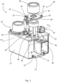
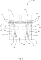
- the hydraulic pump system 10 includes a housing 12 defining a tank 14 for containing hydraulic fluid 16 in use.
- the hydraulic pump system also includes three pump modules 18 (one of which is obscured by the exploded/removed pump module 18 at the front of the figure). In alternative embodiments, more or fewer than three pump modules 18 are provided.
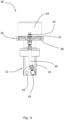
- Each pump module 18 includes a mounting portion 20 and a hydraulic pump 22 for supplying hydraulic fluid 16 from the tank 14 to a hydraulic system (e.g. a hydraulic system of a working vehicle).
- a hydraulic system e.g. a hydraulic system of a working vehicle.
- Each pump module 18 is mounted to the housing 12 by the mounting portion 20.
- Having pump modules 18 (i.e. attachable/detachable self-contained units) mounted to the housing 12 provides a self-contained hydraulic pump system 10 and reduces or removes the length of piping needed to connect the pumps 22 to the hydraulic fluid 16 contained in the tank 14. This reduces the complexity of the system and reduces or removes energy losses which would occur along such piping. This is particularly beneficial for working vehicles, such as battery-powered working vehicles where reduced energy losses result in increased battery life, or fuel cell powered working vehicles where reduced energy losses result in reduced fuel consumption. In addition, this arrangement is more compact than prior art systems in which the hydraulic pump(s) 22 are provided separate from the tank 14.
- the pump modules 18 are each attachable to and detachable from the housing as a self-contained unit. In other words, the pump modules 18 can each be installed or removed from the hydraulic pump system 10 without having to connect/disconnect interconnected components within the pump module 18.
- the mounting portion 20 of each pump module 18 includes a flange 32 for surrounding a perimeter of an aperture 30 of the housing 12 when the pump module 18 is coupled to the housing 12 in use. Having a flange 32 which surrounds a perimeter of an aperture 30 of the housing 12 allows the aperture 30 to be completely covered by the mounting portion 20 (which is useful for preventing ingress of dirt or debris, and/or leakage of fluid from the aperture 30). Such a flange 32 also provides an abutment surface which indicates when the pump module 18 has been correctly positioned relative to the housing 12.
- the mounting portion 20 of each pump module 18 includes a flange which only partially surrounds a perimeter of an aperture 30 of the housing 12.
- the mounting portion 20 includes a plurality of projections or flanges arranged circumferentially around an aperture 30 of the housing 12 in use.
- each pump module 18 is mounted to the housing 12 via a releasable fastening. Having a releasable fastening allows the pump modules 18 to be easily removed/installed for maintenance or replacement purposes.
- through-hole shall be interpreted as a non-threaded hole
- threaded holes shall be interpreted as a blind or through-hole comprising threads.
- the mounting portion 20 of each pump module 18 is fixedly attached to the housing 12 (e.g. via welding or adhesive). Fixedly attaching the mounting portions 20 to the housing 12 ensures a robust connection and can contribute to sealing of the apertures 30 in which the pump modules 18 are received.
- the mounting portion 20 of each pump module 18 includes a seal 38 for sealing a respective aperture 30 when the pump module 18 is coupled to the housing 12 in use.
- a seal 38 e.g. a compressible seal such as a gasket
- offers a reliable means of sealing an aperture 30, particularly under pressure e.g. a bolting pressure exerted on the compressible seal 38 when the mounting portion 20 is secured to the housing 12 via one or more bolts).
- the mounting portion 20 of each pump module 18 includes a seal surface instead of, or in addition to, the seal 38.
- a seal surface instead of, or in addition to, the seal 38.
- a flat metal surface intended to form a metal-to-metal seal with the housing when the mounting portion 20 is fixed to the housing under pressure (e.g. bolting pressure).
- each pump module 18 includes a hydraulic supply port 42 coupled to the hydraulic supply line 40 of the pump module 18 for connection to a hydraulic system in order to supply hydraulic fluid 16 from the pump module 18 to the hydraulic system.
- Each of the hydraulic supply ports 42 is arranged to be external to the tank 14 when its respective pump module 18 is mounted to the housing 12. Such a hydraulic supply port 42 allows the hydraulic pump modules 18 to be easily connected to a hydraulic system (e.g. for moving hydraulic actuators in a hydraulic system for a working vehicle).
- each of the pump modules 18 also includes an electric motor 44 for driving the hydraulic pump 22 of the pump module 18.
- having an electric motor 44 for each pump module 18 allows flow of hydraulic fluid 16 from each module 18 to be controlled independently of the other modules 18. This allows optimal pump flow rates to be set for each pump module 18, in contrast to prior art hydraulic systems that are driven by an internal combustion engine (ICE) which results in the hydraulic pump(s) outputting hydraulic fluid whenever the ICE is running (even if not required by hydraulically actuated devices of the hydraulic system).
- ICE internal combustion engine
- the hydraulic system also includes three inverters 46 to control frequency of power supplied to the electric motors 44 of the pump modules 18.
- Such an inverter arrangement enables variable speed control of the electric motors 44 and DC to AC power smoothing/conversion. This is useful in applications where the electric motors 44 are powered by a DC electricity source (e.g. a battery on an electric working vehicle or a fuel cell on a fuel cell powered vehicle).
- a DC electricity source e.g. a battery on an electric working vehicle or a fuel cell on a fuel cell powered vehicle.
- each pump module 18 is connected to the hydraulic pump 22 of the pump module 18 by a common drive shaft 54.
- Connecting a hydraulic pump 22 to an electric motor 44 via a common drive shaft 54 offers a simple and reliable means for driving the hydraulic pump 22 by the electric motor 44.
- the electric motor 44 of each pump module 18 is connected to the hydraulic pump 22 of the pump module 18 by a gearbox. Connecting a hydraulic pump 22 to an electric motor 44 via a gearbox allows the electric motor 44 and hydraulic pump 22 to each be run in their optimal rotational speed ranges (which may differ), which increases the efficiency of the hydraulic pump system 10.
- the hydraulic pump system 10 also includes a filter arrangement 56 for filtering hydraulic fluid 16 input to the tank 14 (e.g. hydraulic fluid 16 returning from one or more hydraulically-actuated devices of a working vehicle). Having such a filter arrangement 56 removes debris entrained in the hydraulic fluid 16 prior to entering the tank 14 (e.g. debris formed via erosion of components in a hydraulic system) which improves the efficiency of the hydraulic system and reduces the likelihood of damage to components such as the hydraulic pump 22.
- the filter arrangement 56 is mounted on the housing 12 and extends partially into the tank 14 similarly to the pump modules 18, which provides a compact and self-contained arrangement.
- the filter arrangement 56 is provided external to the housing 12 (e.g. as a separate unit connected to the tank 14 via a pipe).
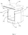
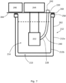
- the outer casing 212a can be formed of plastics material, metallic material (e.g. steel or aluminium) or any other suitable material.
- the inner liner 212b can be formed of plastics material, metallic material (e.g. steel or aluminium) or any other suitable material.
- a cover 266 is provided for the components which are external to the tank 214 (i.e. electric motors 244, inverters 246 and other electronics).
- the cover 266 protects such components from impact, dirt and debris, and also reduces the transmission of noise generated by these components, which results in a quieter pump system 210.
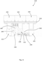
- the working vehicle 100 includes a working arm 102 controlled by a plurality of hydraulic actuators 104.
- the working vehicle 100 also includes a pair of left and right tracks 106 for moving the working vehicle 100.
- the left and right tracks 106 are driven by respective hydraulic motors.
- a set of user inputs 50 e.g. joy-sticks, levers, buttons, pedals etc.
Landscapes
- Engineering & Computer Science (AREA)
- General Engineering & Computer Science (AREA)
- Mechanical Engineering (AREA)
- Mining & Mineral Resources (AREA)
- Civil Engineering (AREA)
- Structural Engineering (AREA)
- Physics & Mathematics (AREA)
- Fluid Mechanics (AREA)
- Chemical & Material Sciences (AREA)
- Analytical Chemistry (AREA)
- Details Of Reciprocating Pumps (AREA)
- Supply Devices, Intensifiers, Converters, And Telemotors (AREA)
Priority Applications (1)
| Application Number | Priority Date | Filing Date | Title |
|---|---|---|---|
| EP25181621.1A EP4596879A3 (de) | 2021-03-08 | 2022-03-02 | Hydraulisches pumpensystem |
Applications Claiming Priority (2)
| Application Number | Priority Date | Filing Date | Title |
|---|---|---|---|
| GB2103209.9A GB2604609B (en) | 2021-03-08 | 2021-03-08 | Hydraulic pump system |
| EP22275025.9A EP4056847B1 (de) | 2021-03-08 | 2022-03-02 | Hydraulikpumpensystem |
Related Parent Applications (2)
| Application Number | Title | Priority Date | Filing Date |
|---|---|---|---|
| EP22275025.9A Division EP4056847B1 (de) | 2021-03-08 | 2022-03-02 | Hydraulikpumpensystem |
| EP22275025.9A Division-Into EP4056847B1 (de) | 2021-03-08 | 2022-03-02 | Hydraulikpumpensystem |
Related Child Applications (1)
| Application Number | Title | Priority Date | Filing Date |
|---|---|---|---|
| EP25181621.1A Division EP4596879A3 (de) | 2021-03-08 | 2022-03-02 | Hydraulisches pumpensystem |
Publications (4)
| Publication Number | Publication Date |
|---|---|
| EP4397860A2 true EP4397860A2 (de) | 2024-07-10 |
| EP4397860A3 EP4397860A3 (de) | 2024-09-25 |
| EP4397860B1 EP4397860B1 (de) | 2025-06-18 |
| EP4397860C0 EP4397860C0 (de) | 2025-06-18 |
Family
ID=75472583
Family Applications (3)
| Application Number | Title | Priority Date | Filing Date |
|---|---|---|---|
| EP24175974.5A Active EP4397860B1 (de) | 2021-03-08 | 2022-03-02 | Hydraulisches pumpensystem |
| EP22275025.9A Active EP4056847B1 (de) | 2021-03-08 | 2022-03-02 | Hydraulikpumpensystem |
| EP25181621.1A Pending EP4596879A3 (de) | 2021-03-08 | 2022-03-02 | Hydraulisches pumpensystem |
Family Applications After (2)
| Application Number | Title | Priority Date | Filing Date |
|---|---|---|---|
| EP22275025.9A Active EP4056847B1 (de) | 2021-03-08 | 2022-03-02 | Hydraulikpumpensystem |
| EP25181621.1A Pending EP4596879A3 (de) | 2021-03-08 | 2022-03-02 | Hydraulisches pumpensystem |
Country Status (5)
| Country | Link |
|---|---|
| US (1) | US12180948B2 (de) |
| EP (3) | EP4397860B1 (de) |
| CN (1) | CN115045870A (de) |
| BR (1) | BR102022004254A2 (de) |
| GB (1) | GB2604609B (de) |
Families Citing this family (7)
| Publication number | Priority date | Publication date | Assignee | Title |
|---|---|---|---|---|
| FR3107572B1 (fr) * | 2020-02-21 | 2022-02-25 | Air Liquide | Appareil de compression et station de remplissage comprenant un tel appareil |
| EP4306724A1 (de) | 2022-07-15 | 2024-01-17 | Yanmar Holdings Co., Ltd. | Elektrische arbeitsmaschine |
| US20240240658A1 (en) * | 2023-01-17 | 2024-07-18 | Narendra Gupta | Hydraulic power pack module |
| GB2629410B (en) | 2023-04-27 | 2026-03-18 | Bamford Excavators Ltd | A hydraulic pump arrangement |
| SE2351336A1 (en) * | 2023-11-21 | 2025-05-22 | Husqvarna Ab | Track adjustment mechanisms for demolition robots |
| SE547211C2 (en) * | 2024-02-27 | 2025-06-03 | Gds Geo Drilling Solutions Ab | Pumping assembly |
| JP2025154225A (ja) * | 2024-03-29 | 2025-10-10 | 株式会社竹内製作所 | 作業用車両 |
Family Cites Families (26)
| Publication number | Priority date | Publication date | Assignee | Title |
|---|---|---|---|---|
| US2456339A (en) * | 1946-06-25 | 1948-12-14 | Darwin B Stricklin | Pump construction |
| US3212280A (en) * | 1963-11-22 | 1965-10-19 | Air Prod & Chem | Volatile liquid pumping system |
| US4047845A (en) * | 1975-12-22 | 1977-09-13 | Auto Research Corporation | Cyclic pump |
| US5295795A (en) | 1991-04-12 | 1994-03-22 | Hitachi Construction Machinery Co., Ltd. | Hydraulic drive system for construction machine |
| DE4120665A1 (de) * | 1991-06-22 | 1992-12-24 | Teves Gmbh Alfred | Elektromotorisch angetriebene hydraulikpumpe |
| DE19612582A1 (de) * | 1996-03-29 | 1997-10-02 | Miag Fahrzeugbau Gmbh | Antriebseinheit für ein Fahrzeug |
| DE59802006D1 (de) * | 1997-02-05 | 2001-12-13 | Hoerbiger Hydraulik | Hydraulisches Motorpumpenaggregat |
| DE19959022C1 (de) * | 1999-12-08 | 2001-06-21 | Bosch Gmbh Robert | Antriebseinheit |
| KR100621985B1 (ko) | 2005-08-02 | 2006-09-11 | 볼보 컨스트럭션 이키프먼트 홀딩 스웨덴 에이비 | 주행시스템 |
| US7513393B2 (en) * | 2006-06-16 | 2009-04-07 | Lincoln Industrial Corporation | Container system |
| DE102011106307A1 (de) | 2011-07-01 | 2013-01-03 | Robert Bosch Gmbh | Steueranordnung und Verfahren zum Ansteuern von mehreren hydraulischen Verbrauchern |
| US9239044B2 (en) * | 2012-03-19 | 2016-01-19 | Lincoln Industrial Corporation | Lance pump having horizontally mounted stepper/servo motor |
| US9145660B2 (en) | 2012-08-31 | 2015-09-29 | Caterpillar Inc. | Hydraulic control system having over-pressure protection |
| US9303387B2 (en) | 2012-11-01 | 2016-04-05 | Husco International, Inc. | Hydraulic system with open loop electrohydraulic pressure compensation |
| JP6147229B2 (ja) * | 2014-07-02 | 2017-06-14 | 日精樹脂工業株式会社 | 電動ポンプ装置 |
| JP6324347B2 (ja) | 2015-06-01 | 2018-05-16 | 日立建機株式会社 | 建設機械の油圧制御装置 |
| US10584722B2 (en) | 2015-09-29 | 2020-03-10 | Hitachi Construction Machinery Co., Ltd. | Hydraulic fluid energy regeneration apparatus of work machine |
| DE102015119055B4 (de) * | 2015-11-06 | 2019-05-09 | Knorr-Bremse Systeme für Schienenfahrzeuge GmbH | Hydrogerät |
| EP3428457B1 (de) | 2016-03-10 | 2021-05-05 | Hitachi Construction Machinery Co., Ltd. | Baumaschine mit antikavitationssystem für den hydraulikaktuator |
| US11018610B2 (en) * | 2017-01-27 | 2021-05-25 | Franklin Electric Co., Inc. | Motor drive system and method |
| JP6596458B2 (ja) | 2017-03-13 | 2019-10-23 | 株式会社日立建機ティエラ | 電動式油圧作業機械の油圧駆動装置 |
| JP6676827B2 (ja) * | 2017-05-09 | 2020-04-08 | 日立建機株式会社 | 作業機械 |
| JP6450487B1 (ja) | 2018-05-15 | 2019-01-09 | 川崎重工業株式会社 | 油圧ショベル駆動システム |
| WO2020049668A1 (ja) | 2018-09-05 | 2020-03-12 | 株式会社日立建機ティエラ | 電動式油圧作業機械の油圧駆動装置 |
| DE102019003342A1 (de) * | 2019-05-11 | 2020-11-12 | Hydac Fluidtechnik Gmbh | Hydraulisches Antriebssystem |
| ES2958107T3 (es) * | 2019-08-16 | 2024-02-01 | Bucher Municipal Ag | Máquina de trabajo autopropulsada sobre una superficie de suelo firme, con un grupo hidráulico montado sobre un bastidor para accionar la máquina de trabajo |
-
2021
- 2021-03-08 GB GB2103209.9A patent/GB2604609B/en active Active
-
2022
- 2022-03-02 EP EP24175974.5A patent/EP4397860B1/de active Active
- 2022-03-02 EP EP22275025.9A patent/EP4056847B1/de active Active
- 2022-03-02 EP EP25181621.1A patent/EP4596879A3/de active Pending
- 2022-03-08 BR BR102022004254-3A patent/BR102022004254A2/pt unknown
- 2022-03-08 US US17/689,980 patent/US12180948B2/en active Active
- 2022-03-08 CN CN202210220579.7A patent/CN115045870A/zh active Pending
Also Published As
| Publication number | Publication date |
|---|---|
| EP4397860A3 (de) | 2024-09-25 |
| GB2604609B (en) | 2025-04-09 |
| CN115045870A (zh) | 2022-09-13 |
| EP4397860B1 (de) | 2025-06-18 |
| EP4056847A1 (de) | 2022-09-14 |
| BR102022004254A2 (pt) | 2022-09-20 |
| EP4056847B1 (de) | 2024-06-19 |
| EP4596879A3 (de) | 2025-08-20 |
| US12180948B2 (en) | 2024-12-31 |
| US20220282718A1 (en) | 2022-09-08 |
| EP4596879A2 (de) | 2025-08-06 |
| EP4397860C0 (de) | 2025-06-18 |
| GB202103209D0 (en) | 2021-04-21 |
| GB2604609A (en) | 2022-09-14 |
Similar Documents
| Publication | Publication Date | Title |
|---|---|---|
| EP4056847B1 (de) | Hydraulikpumpensystem | |
| US5540563A (en) | Unitary housing for double hydraulic unit | |
| US20030188530A1 (en) | Cylinder driving system and energy regenerating method thereof | |
| KR20120051730A (ko) | 작업 기계의 전액 구동 시스템 | |
| CN114987130A (zh) | Mpe车轴组的外壳结构 | |
| JP7715813B2 (ja) | 増加したトルク用のマウント構成を備えた液圧ポンプまたはモーター | |
| CN118284760A (zh) | 电气化车桥的动力设备 | |
| US10919376B2 (en) | Recess-mounted hydraulic pump cartridge and work vehicle drivetrain therewith | |
| WO2016000732A1 (en) | A turbocharger unit | |
| GB2701499A (en) | Working vehicle | |
| CN215890441U (zh) | 一种带吸油滤清器的电油泵 | |
| CN212003821U (zh) | 多功能独立散热系统 | |
| CN217421714U (zh) | 一种液压系统动力元件并联装置 | |
| CN112524027A (zh) | 组合式油封结构及空压机 | |
| KR101804437B1 (ko) | 개구 폐색 커버 및 당해 개구 폐색 커버를 구비한 건설기계 | |
| US12454952B2 (en) | Hydraulic pump arrangement | |
| CN220483085U (zh) | 一种挖掘装载机油箱组合结构 | |
| CN202642085U (zh) | 一种带多输出的船用齿轮箱 | |
| WO2010077786A2 (en) | Externally mounted variator for split torque transmission | |
| CN223263344U (zh) | 一种森林电力远程供水机器人 | |
| CN216044388U (zh) | 一种可变量低脉动齿轮泵 | |
| US12590580B2 (en) | Pump mounting flange | |
| CN218818005U (zh) | 一种轮式拖拉机动力换向壳体的连接结构 | |
| US20260085681A1 (en) | Pump mounting flange | |
| US20260085684A1 (en) | Pump mounting flange |
Legal Events
| Date | Code | Title | Description |
|---|---|---|---|
| PUAI | Public reference made under article 153(3) epc to a published international application that has entered the european phase |
Free format text: ORIGINAL CODE: 0009012 |
|
| STAA | Information on the status of an ep patent application or granted ep patent |
Free format text: STATUS: REQUEST FOR EXAMINATION WAS MADE |
|
| 17P | Request for examination filed |
Effective date: 20240515 |
|
| AC | Divisional application: reference to earlier application |
Ref document number: 4056847 Country of ref document: EP Kind code of ref document: P |
|
| AK | Designated contracting states |
Kind code of ref document: A2 Designated state(s): AL AT BE BG CH CY CZ DE DK EE ES FI FR GB GR HR HU IE IS IT LI LT LU LV MC MK MT NL NO PL PT RO RS SE SI SK SM TR |
|
| REG | Reference to a national code |
Ref country code: DE Ref legal event code: R079 Free format text: PREVIOUS MAIN CLASS: F04B0023040000 Ipc: F04B0017030000 Ref country code: DE Ref legal event code: R079 Ref document number: 602022016257 Country of ref document: DE Free format text: PREVIOUS MAIN CLASS: F04B0023040000 Ipc: F04B0017030000 |
|
| PUAL | Search report despatched |
Free format text: ORIGINAL CODE: 0009013 |
|
| AK | Designated contracting states |
Kind code of ref document: A3 Designated state(s): AL AT BE BG CH CY CZ DE DK EE ES FI FR GB GR HR HU IE IS IT LI LT LU LV MC MK MT NL NO PL PT RO RS SE SI SK SM TR |
|
| RIC1 | Information provided on ipc code assigned before grant |
Ipc: F04B 53/00 20060101ALI20240821BHEP Ipc: F04B 23/04 20060101ALI20240821BHEP Ipc: F04B 23/02 20060101ALI20240821BHEP Ipc: F04B 17/03 20060101AFI20240821BHEP |
|
| GRAP | Despatch of communication of intention to grant a patent |
Free format text: ORIGINAL CODE: EPIDOSNIGR1 |
|
| STAA | Information on the status of an ep patent application or granted ep patent |
Free format text: STATUS: GRANT OF PATENT IS INTENDED |
|
| INTG | Intention to grant announced |
Effective date: 20250113 |
|
| P01 | Opt-out of the competence of the unified patent court (upc) registered |
Free format text: CASE NUMBER: APP_53/2025 Effective date: 20250102 |
|
| GRAS | Grant fee paid |
Free format text: ORIGINAL CODE: EPIDOSNIGR3 |
|
| GRAA | (expected) grant |
Free format text: ORIGINAL CODE: 0009210 |
|
| STAA | Information on the status of an ep patent application or granted ep patent |
Free format text: STATUS: THE PATENT HAS BEEN GRANTED |
|
| AC | Divisional application: reference to earlier application |
Ref document number: 4056847 Country of ref document: EP Kind code of ref document: P |
|
| AK | Designated contracting states |
Kind code of ref document: B1 Designated state(s): AL AT BE BG CH CY CZ DE DK EE ES FI FR GB GR HR HU IE IS IT LI LT LU LV MC MK MT NL NO PL PT RO RS SE SI SK SM TR |
|
| REG | Reference to a national code |
Ref country code: GB Ref legal event code: FG4D |
|
| REG | Reference to a national code |
Ref country code: CH Ref legal event code: EP |
|
| REG | Reference to a national code |
Ref country code: DE Ref legal event code: R096 Ref document number: 602022016257 Country of ref document: DE |
|
| REG | Reference to a national code |
Ref country code: CH Ref legal event code: EP |
|
| REG | Reference to a national code |
Ref country code: IE Ref legal event code: FG4D |
|
| U01 | Request for unitary effect filed |
Effective date: 20250707 |
|
| U07 | Unitary effect registered |
Designated state(s): AT BE BG DE DK EE FI FR IT LT LU LV MT NL PT RO SE SI Effective date: 20250711 |
|
| PG25 | Lapsed in a contracting state [announced via postgrant information from national office to epo] |
Ref country code: NO Free format text: LAPSE BECAUSE OF FAILURE TO SUBMIT A TRANSLATION OF THE DESCRIPTION OR TO PAY THE FEE WITHIN THE PRESCRIBED TIME-LIMIT Effective date: 20250918 Ref country code: GR Free format text: LAPSE BECAUSE OF FAILURE TO SUBMIT A TRANSLATION OF THE DESCRIPTION OR TO PAY THE FEE WITHIN THE PRESCRIBED TIME-LIMIT Effective date: 20250919 |
|
| PG25 | Lapsed in a contracting state [announced via postgrant information from national office to epo] |
Ref country code: HR Free format text: LAPSE BECAUSE OF FAILURE TO SUBMIT A TRANSLATION OF THE DESCRIPTION OR TO PAY THE FEE WITHIN THE PRESCRIBED TIME-LIMIT Effective date: 20250618 |
|
| PG25 | Lapsed in a contracting state [announced via postgrant information from national office to epo] |
Ref country code: RS Free format text: LAPSE BECAUSE OF FAILURE TO SUBMIT A TRANSLATION OF THE DESCRIPTION OR TO PAY THE FEE WITHIN THE PRESCRIBED TIME-LIMIT Effective date: 20250918 |
|
| PG25 | Lapsed in a contracting state [announced via postgrant information from national office to epo] |
Ref country code: IS Free format text: LAPSE BECAUSE OF FAILURE TO SUBMIT A TRANSLATION OF THE DESCRIPTION OR TO PAY THE FEE WITHIN THE PRESCRIBED TIME-LIMIT Effective date: 20251018 |
|
| PG25 | Lapsed in a contracting state [announced via postgrant information from national office to epo] |
Ref country code: SM Free format text: LAPSE BECAUSE OF FAILURE TO SUBMIT A TRANSLATION OF THE DESCRIPTION OR TO PAY THE FEE WITHIN THE PRESCRIBED TIME-LIMIT Effective date: 20250618 |
|
| PG25 | Lapsed in a contracting state [announced via postgrant information from national office to epo] |
Ref country code: CZ Free format text: LAPSE BECAUSE OF FAILURE TO SUBMIT A TRANSLATION OF THE DESCRIPTION OR TO PAY THE FEE WITHIN THE PRESCRIBED TIME-LIMIT Effective date: 20250618 |
|
| PG25 | Lapsed in a contracting state [announced via postgrant information from national office to epo] |
Ref country code: PL Free format text: LAPSE BECAUSE OF FAILURE TO SUBMIT A TRANSLATION OF THE DESCRIPTION OR TO PAY THE FEE WITHIN THE PRESCRIBED TIME-LIMIT Effective date: 20250618 |
|
| PG25 | Lapsed in a contracting state [announced via postgrant information from national office to epo] |
Ref country code: SK Free format text: LAPSE BECAUSE OF FAILURE TO SUBMIT A TRANSLATION OF THE DESCRIPTION OR TO PAY THE FEE WITHIN THE PRESCRIBED TIME-LIMIT Effective date: 20250618 |
|
| PG25 | Lapsed in a contracting state [announced via postgrant information from national office to epo] |
Ref country code: ES Free format text: LAPSE BECAUSE OF FAILURE TO SUBMIT A TRANSLATION OF THE DESCRIPTION OR TO PAY THE FEE WITHIN THE PRESCRIBED TIME-LIMIT Effective date: 20250618 |
|
| PGFP | Annual fee paid to national office [announced via postgrant information from national office to epo] |
Ref country code: GB Payment date: 20260316 Year of fee payment: 5 |
|
| U20 | Renewal fee for the european patent with unitary effect paid |
Year of fee payment: 5 Effective date: 20260316 |
|
| PLBE | No opposition filed within time limit |
Free format text: ORIGINAL CODE: 0009261 |
|
| STAA | Information on the status of an ep patent application or granted ep patent |
Free format text: STATUS: NO OPPOSITION FILED WITHIN TIME LIMIT |
|
| REG | Reference to a national code |
Ref country code: CH Ref legal event code: L10 Free format text: ST27 STATUS EVENT CODE: U-0-0-L10-L00 (AS PROVIDED BY THE NATIONAL OFFICE) Effective date: 20260430 |