EP4397864A1 - Motopompe - Google Patents
Motopompe Download PDFInfo
- Publication number
- EP4397864A1 EP4397864A1 EP22863954.8A EP22863954A EP4397864A1 EP 4397864 A1 EP4397864 A1 EP 4397864A1 EP 22863954 A EP22863954 A EP 22863954A EP 4397864 A1 EP4397864 A1 EP 4397864A1
- Authority
- EP
- European Patent Office
- Prior art keywords
- motor pump
- impeller
- rotor
- motor
- stator
- Prior art date
- Legal status (The legal status is an assumption and is not a legal conclusion. Google has not performed a legal analysis and makes no representation as to the accuracy of the status listed.)
- Pending
Links
Images





















Classifications
-
- F—MECHANICAL ENGINEERING; LIGHTING; HEATING; WEAPONS; BLASTING
- F04—POSITIVE - DISPLACEMENT MACHINES FOR LIQUIDS; PUMPS FOR LIQUIDS OR ELASTIC FLUIDS
- F04D—NON-POSITIVE-DISPLACEMENT PUMPS
- F04D13/00—Pumping installations or systems
- F04D13/02—Units comprising pumps and their driving means
- F04D13/06—Units comprising pumps and their driving means the pump being electrically driven
- F04D13/0606—Canned motor pumps
- F04D13/0633—Details of the bearings
-
- F—MECHANICAL ENGINEERING; LIGHTING; HEATING; WEAPONS; BLASTING
- F04—POSITIVE - DISPLACEMENT MACHINES FOR LIQUIDS; PUMPS FOR LIQUIDS OR ELASTIC FLUIDS
- F04D—NON-POSITIVE-DISPLACEMENT PUMPS
- F04D13/00—Pumping installations or systems
- F04D13/02—Units comprising pumps and their driving means
- F04D13/06—Units comprising pumps and their driving means the pump being electrically driven
-
- F—MECHANICAL ENGINEERING; LIGHTING; HEATING; WEAPONS; BLASTING
- F04—POSITIVE - DISPLACEMENT MACHINES FOR LIQUIDS; PUMPS FOR LIQUIDS OR ELASTIC FLUIDS
- F04D—NON-POSITIVE-DISPLACEMENT PUMPS
- F04D1/00—Radial-flow pumps, e.g. centrifugal pumps; Helico-centrifugal pumps
- F04D1/06—Multi-stage pumps
- F04D1/063—Multi-stage pumps of the vertically split casing type
- F04D1/066—Multi-stage pumps of the vertically split casing type the casing consisting of a plurality of annuli bolted together
-
- F—MECHANICAL ENGINEERING; LIGHTING; HEATING; WEAPONS; BLASTING
- F04—POSITIVE - DISPLACEMENT MACHINES FOR LIQUIDS; PUMPS FOR LIQUIDS OR ELASTIC FLUIDS
- F04D—NON-POSITIVE-DISPLACEMENT PUMPS
- F04D13/00—Pumping installations or systems
- F04D13/02—Units comprising pumps and their driving means
- F04D13/06—Units comprising pumps and their driving means the pump being electrically driven
- F04D13/0606—Canned motor pumps
- F04D13/064—Details of the magnetic circuit
-
- F—MECHANICAL ENGINEERING; LIGHTING; HEATING; WEAPONS; BLASTING
- F04—POSITIVE - DISPLACEMENT MACHINES FOR LIQUIDS; PUMPS FOR LIQUIDS OR ELASTIC FLUIDS
- F04D—NON-POSITIVE-DISPLACEMENT PUMPS
- F04D13/00—Pumping installations or systems
- F04D13/02—Units comprising pumps and their driving means
- F04D13/06—Units comprising pumps and their driving means the pump being electrically driven
- F04D13/0646—Units comprising pumps and their driving means the pump being electrically driven the hollow pump or motor shaft being the conduit for the working fluid
-
- F—MECHANICAL ENGINEERING; LIGHTING; HEATING; WEAPONS; BLASTING
- F04—POSITIVE - DISPLACEMENT MACHINES FOR LIQUIDS; PUMPS FOR LIQUIDS OR ELASTIC FLUIDS
- F04D—NON-POSITIVE-DISPLACEMENT PUMPS
- F04D29/00—Details, component parts, or accessories
- F04D29/04—Shafts or bearings, or assemblies thereof
- F04D29/041—Axial thrust balancing
- F04D29/0413—Axial thrust balancing hydrostatic; hydrodynamic thrust bearings
-
- F—MECHANICAL ENGINEERING; LIGHTING; HEATING; WEAPONS; BLASTING
- F04—POSITIVE - DISPLACEMENT MACHINES FOR LIQUIDS; PUMPS FOR LIQUIDS OR ELASTIC FLUIDS
- F04D—NON-POSITIVE-DISPLACEMENT PUMPS
- F04D29/00—Details, component parts, or accessories
- F04D29/04—Shafts or bearings, or assemblies thereof
- F04D29/046—Bearings
-
- F—MECHANICAL ENGINEERING; LIGHTING; HEATING; WEAPONS; BLASTING
- F04—POSITIVE - DISPLACEMENT MACHINES FOR LIQUIDS; PUMPS FOR LIQUIDS OR ELASTIC FLUIDS
- F04D—NON-POSITIVE-DISPLACEMENT PUMPS
- F04D29/00—Details, component parts, or accessories
- F04D29/04—Shafts or bearings, or assemblies thereof
- F04D29/046—Bearings
- F04D29/047—Bearings hydrostatic; hydrodynamic
- F04D29/0473—Bearings hydrostatic; hydrodynamic for radial pumps
-
- F—MECHANICAL ENGINEERING; LIGHTING; HEATING; WEAPONS; BLASTING
- F04—POSITIVE - DISPLACEMENT MACHINES FOR LIQUIDS; PUMPS FOR LIQUIDS OR ELASTIC FLUIDS
- F04D—NON-POSITIVE-DISPLACEMENT PUMPS
- F04D29/00—Details, component parts, or accessories
- F04D29/08—Sealings
- F04D29/086—Sealings especially adapted for liquid pumps
-
- F—MECHANICAL ENGINEERING; LIGHTING; HEATING; WEAPONS; BLASTING
- F04—POSITIVE - DISPLACEMENT MACHINES FOR LIQUIDS; PUMPS FOR LIQUIDS OR ELASTIC FLUIDS
- F04D—NON-POSITIVE-DISPLACEMENT PUMPS
- F04D29/00—Details, component parts, or accessories
- F04D29/08—Sealings
- F04D29/16—Sealings between pressure and suction sides
- F04D29/165—Sealings between pressure and suction sides especially adapted for liquid pumps
- F04D29/167—Sealings between pressure and suction sides especially adapted for liquid pumps of a centrifugal flow wheel
-
- F—MECHANICAL ENGINEERING; LIGHTING; HEATING; WEAPONS; BLASTING
- F04—POSITIVE - DISPLACEMENT MACHINES FOR LIQUIDS; PUMPS FOR LIQUIDS OR ELASTIC FLUIDS
- F04D—NON-POSITIVE-DISPLACEMENT PUMPS
- F04D29/00—Details, component parts, or accessories
- F04D29/18—Rotors
- F04D29/22—Rotors specially for centrifugal pumps
- F04D29/2205—Conventional flow pattern
- F04D29/2222—Construction and assembly
-
- F—MECHANICAL ENGINEERING; LIGHTING; HEATING; WEAPONS; BLASTING
- F04—POSITIVE - DISPLACEMENT MACHINES FOR LIQUIDS; PUMPS FOR LIQUIDS OR ELASTIC FLUIDS
- F04D—NON-POSITIVE-DISPLACEMENT PUMPS
- F04D29/00—Details, component parts, or accessories
- F04D29/40—Casings; Connections of working fluid
- F04D29/42—Casings; Connections of working fluid for radial or helico-centrifugal pumps
- F04D29/426—Casings; Connections of working fluid for radial or helico-centrifugal pumps especially adapted for liquid pumps
-
- F—MECHANICAL ENGINEERING; LIGHTING; HEATING; WEAPONS; BLASTING
- F04—POSITIVE - DISPLACEMENT MACHINES FOR LIQUIDS; PUMPS FOR LIQUIDS OR ELASTIC FLUIDS
- F04D—NON-POSITIVE-DISPLACEMENT PUMPS
- F04D29/00—Details, component parts, or accessories
- F04D29/60—Mounting; Assembling; Disassembling
- F04D29/62—Mounting; Assembling; Disassembling of radial or helico-centrifugal pumps
- F04D29/628—Mounting; Assembling; Disassembling of radial or helico-centrifugal pumps especially adapted for liquid pumps
-
- F—MECHANICAL ENGINEERING; LIGHTING; HEATING; WEAPONS; BLASTING
- F05—INDEXING SCHEMES RELATING TO ENGINES OR PUMPS IN VARIOUS SUBCLASSES OF CLASSES F01-F04
- F05D—INDEXING SCHEME FOR ASPECTS RELATING TO NON-POSITIVE-DISPLACEMENT MACHINES OR ENGINES, GAS-TURBINES OR JET-PROPULSION PLANTS
- F05D2240/00—Components
- F05D2240/50—Bearings
Definitions
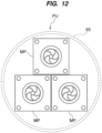
- one inverter 60 is connected to the stators 3 of the motor pumps MP.
- the inverter 60 can independently control each of the motor pumps MP. Therefore, the operator can operate at least one motor pump MP at any timing depending on the operating conditions of the pump unit.
- FIG. 13A is a view showing a motor pump as a comparative example.
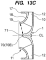
- FIGS. 13B and 13C are views showing another embodiment of the motor pump.
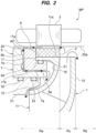
- the motor pump as a comparative example includes a rotary shaft RS, but the motor pump MP according to the embodiment does not have the rotary shaft RS. Instead, the impeller 1 includes a rounded convex portion 70 arranged at its central portion.
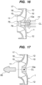
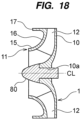
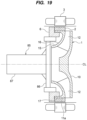
- the motor pump rotates the impeller 1 at high speed by its operation. If a center of gravity of the impeller 1 is shifted, the impeller 1 rotates at high speed in an eccentric state. As a result, noise may be generated, and in the worst case, the motor pump may break down.
- FIG. 20 is a view showing another embodiment of the method of balancing.
- the rotor 2 includes an annular iron core 2a, and a plurality of magnets 2b embedded in the iron core 2a.
- the magnets 2b are arranged at equal intervals along a circumferential direction of the rotor 2 (more specifically, the iron core 2a).
- the operator performs a process of forming a plurality of weight insertion holes 90 along the circumferential direction of the rotor 2.
- the process of forming the weight insertion hole 90 is performed when manufacturing of the iron core 2a.
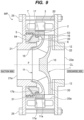
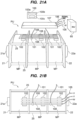
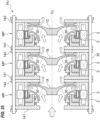
- the motor pump MP has a compact structure that makes effective use of dead space. Therefore, by connecting these motor pumps MP in series, the pump unit PU can be operated at a pump head without increasing its installation area.
- the motor pump MP is the rotating machine with the permanent magnet type motor. Such motor rotates uncontrolled by forcibly applying a voltage at start up.
- the control of the rotational speed of the motor pump MP by the inverter 60 is started immediately, and then a steady operation of motor pump MP is started.
- the motor pump MP in the embodiment has a structure in which a flow path is formed inside the rotor 2, and the outer diameter of the rotor 2 is designed to be large.
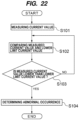
- the memory 100b of the control device 100 stores data indicating a correlation between the flow rate of the liquid to be handled during normal operation and the current supplied to the motor pumps MP during normal operation.
- the control device 100 determines the assumed current value based on this data, and calculates the lower limit current value based on the determined assumed current value.
- the above formula can be used as an example of the calculation formula for the lower limit current value.
- the control device 100 compares the measured current value during the steady operation of the motor pumps MP with the lower limit current value, and when the measured current value is lower than the lower limit current value, it is determined that at least one of the motor pump MP has an abnormality.
- the pump unit PU includes the current sensor 101 (first current sensor 101) arranged between the first motor pump MP and the second motor pump MP, and the current sensor 101 (second current sensor 101) arranged between the second motor pump MP and the third motor pump MP.
- control device 100 determines that the measured current value Amax is lower than the lower limit current value, and determines that there is no abnormality in the first motor pump MP and the second motor pump MP, the control device 100 determines that the third motor pump MP has an abnormality.
- control device 100 may start the first motor pump MP, then start the second motor pump MP, or after starting the third motor pump MP, the control device 100 may start the first motor pump MP adjacent to the third motor pump MP.
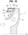
- the iron core 2a of the rotor 2 is joined to the protrusion 117 by adhesive, press fit, shrink fit, welding, or the like.
- the cover 110 is joined to the impeller 1 by adhesive, press fitting, shrink fitting, welding, or the like.
- FIG. 26 is a view showing another embodiment of the impeller. In this embodiment, illustration of the bearing 5 is omitted. As shown in FIG. 26 , the rotor 2 is fixed to the outer edge portion 11a of the side plate 11 so as to block the flow path (i.e., an outlet flow path) of the impeller 1 formed between the main plate 10 and the side plate 11. Also in this embodiment, the rotor 2 is arranged in the suction side region Ra.
- the liquid to be handled passing through the outlet flow path collides with an inner circumferential surface of the rotor 2, and a direction of the liquid to be handled is changed. Thereafter, the liquid to be handled passes through a gap between the main plate 10 and the discharge casing 22, and is discharged from the outlet 22a.
- the motor pump MP includes two impellers 1, but the number of impellers 1 is not limited to this embodiment.
- the motor pump MP may include a plurality of intermediate casings 125 depending on the number of impellers 1.
- the motor pump MP may include a plurality of impellers 1 including at least the first impeller 1A and the second impeller 1B.
- the first impeller 1A and the second impeller 1B are supported not only by the bearing 5 but also by the discharge side bearing 128.
- the discharge side bearing 128 is a radial bearing.
- a size of a motor capacity of the motor pump MP depends on a length of a length Lg of the stator 3.
- the size of the pump head of the motor pump MP depends on a size of a diameter D1 of the impeller 1.
- the magnitude of the flow rate of the motor pump MP depends on the size of an outlet flow path B2 of the impeller 1.
- the motor pump MPC has a larger motor capacity than that of the motor pump MPA (i.e., LgC > LgA).
- the motor pump MPC has a higher flow rate capacity than that of the motor pump MPA (i.e., B2C > B2A).
- the pump unit PU can easily change its performance without changing the size of the components (e.g., the bearing 5, the suction casing 21, and the discharge casing 22) that are not dependent on the pump head or the flow rate capacity.
- FIG. 31A is a sectional view of a motor pump according to another embodiment
- FIG. 31B is a view of the motor pump shown in FIG. 31A viewed from an axial direction.
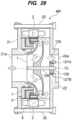
- the motor pump MP may include a swiveling stopper (in other words, whirl stopper) 130 arranged on the back side of the impeller 1.
- one swiveling stopper 130 is arranged, but at least one swiveling stopper 130 may be arranged.
- the swiveling stopper 130 is fixed to the discharge casing 22, and faces the main plate 10 of the impeller 1.
- the swiveling stopper 130 can prevent the liquid to be handled discharged from the impeller 1 from swiveling between the impeller 1 and the discharge casing 22.
- FIG. 39 is a view showing the rotor inserted into the rotor holder.
- the inner annular portion 232 may have a plurality of protrusions 235 formed at a contact portion with the rotor 2.
- the protrusion 235 of the inner annular portion 232 faces the inner surface 230 of the rotor 2, and the rotor 2 is in contact with the protrusion 235. Also with such a configuration, the contact area of the rotor 2 with the rotor holder 200 can be reduced, and as a result, the deformation of the rotor holder 200 can be prevented.
- the motor pump MP includes a stator casing 20 that accommodates the stator 3 and is integrally resin molded with the stator 3.
- the stator 3 includes a stator core 3a and a coil 3b wound around the stator core 3a via an insulating member 220.
- An example of the insulating member 220 includes insulating paper, resin, or the like.
- the resin constituting the stator casing 20 is made of a material (similar to a potting material) that is insulating and has excellent thermal conductivity.
- a resin is poured into the mold with the ring holder 252 and the rotor 2 attached to the ring holder 252 set in the mold.
- the resin forming the accommodating portion 251 of the rotor holder 200 wraps around the rotor 2, and as a result, the accommodating portion 251 seals the rotor 2.
- the rotation prevention structure may be a gear-shaped notch (not shown) formed in each of the ring portion 253 and the bent portion 254.
- the notches are formed along the circumferential direction of the ring holder 252.
- a primer may be applied to a surface of the ring holder 252 in advance to remove oxides on the surface of the ring holder 252.
- the intermediate casing 275 is constructed from a different material than the stator casing 20, but the intermediate casing 275 and the stator casing 20 may be constructed from the same material.
- the return vane 30 fixed to the intermediate casing 275 also serves as a guide vane that guides the liquid to be handled discharged from the first impeller 1A to the second impeller 1B.
- the return vane (and guide vane) 30 can efficiently convert a velocity of the liquid to be handled generated by a centrifugal force of the impeller 1A of the first impeller 1A into the pressure, and guide it to a liquid inlet of the first impeller 1B.
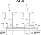
- the motor pump MP includes a sleeve 280 that forms a predetermined distance between the first impeller 1A and the second impeller 1B.
- the sleeve 280 is arranged between the first impeller 1A and the second impeller 1B. By arranging the sleeve 280, the operator can easily manage the distance between the first impeller 1A and the second impeller 1B.
- Each of the first impeller 1A and second impeller 1B has a power transmission structure (e.g., key structure, two-chamfer structure, spline structure, etc.) and is connected to the communication shaft 270 by the structure.
- a power transmission structure e.g., key structure, two-chamfer structure, spline structure, etc.
- each of the first impeller 1A and the second impeller 1B is fixed to the communication shaft 270 by a fastener (e.g., a nut) 273 fastened to the communication shaft 270.
- the sleeve 280 is arranged between the first impeller 1A and the second impeller 1B, and a rotary side bearing body 272 (described below) is arranged between the fastener 273 and the second impeller 1B.
- the sleeve 280 is pressed against the first impeller 1A, and the rotary side bearing body 272 is pressed against the second impeller 1B.
- the first impeller 1A is sandwiched between a tip portion 270a of the communication shaft 270 and the sleeve 280, and the second impeller 1B is sandwiched between the sleeve 280 and the rotary side bearing body 272. In this manner, the first impeller 1A and the second impeller 1B are firmly fixed to the communication shaft 270.
- the tip portion 270a of the communication shaft 270 is arranged on the suction side, and the fastener 273 is arranged on the discharge side.
- the tip portion 270a of the communication shaft 270 may have a hexagonal head or hexagonal hole. This structure allows the operator to firmly tighten the fastener 273 to the communication shaft 270 while fixing the tip portion 270a.
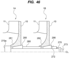
- FIG. 46 is a view showing another embodiment of a connection structure of the first impeller and the second impeller and the communication shaft.
- the motor pump MP includes collets 285 and 286 that fasten each of the first impeller 1A and the second impeller 1B to the communication shaft 270. Since the collets 285 and 286 have the same structure, a structure of the collet 285 will be described below.
- the collet 285 is a cylindrical member having a tapered shape, and has a notch (not shown) extending in the direction of the centerline CL.
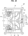
- the motor pump MP includes a second bearing (sliding bearing) 277, which is arranged at a rear of the second impeller 1B and freely supports the communication shaft 270.
- the second bearing 277 includes the rotary side bearing body 272 arranged on the communication shaft 270 side and a stationary side bearing body 271 arranged on the discharge casing 22 side.
- the rotary side bearing body 272 is a rotary side cylindrical body attached to the communication shaft 270
- the stationary side bearing body 271 is a stationary side cylindrical body attached to the discharge casing 22 and surrounding the rotary side bearing body 272 as the rotary side cylindrical body.
- the partition plate 245 of the discharge casing 22 has a bearing supporter 246 that supports the stationary side bearing body 271.
- the stationary side bearing body 271 is fixed to the bearing supporter 246. A small gap is formed between the stationary side bearing body 271 and the rotary side bearing body 272.
- the communication shaft 270 is supported not only by the first bearing 5 fixed to the impeller 1A, but also by the second bearing 277.
- the communication shaft 270 to which the impellers 1 connected has a longer length in the direction of the center line CL.
- the motor pump MP including the first bearing 5 and the second bearing 277 can suppress an axial vibration of the communication shaft 270 due to the increase in the length of the communication shaft 270, and as a result can operate stably.
- a assembly procedure of the motor pump MP is described below. First, the first impeller 1A and the communication shaft 270 are fastened (process 1). Then, the intermediate casing 275 (see FIGS. 43 and 44 ) is inserted into the communication shaft 270 (process 2), and the sleeve 280 is inserted into the communication shaft 270 (process 3). Next, the second impeller 1B is inserted into the communication shaft 270, and the second impeller 1B and the communication shaft 270 are fastened (process 4). The rotary side bearing body 272 is then inserted into the communication shaft 270 (process 5), and the discharge casing 22 is fastened to the stator casing 20 (process 6). The fastener 273 is then fastened to the communication shaft 270 (process 7).
- the operator may perform the process 5, then the process 7, and then process 6. However, as the number of impellers 1 fixed to the communication shaft 270 increases, the communication shaft 270 may tilt, resulting in a position of the communication shaft 270 shifting from the direction of the center line CL.
- the operator attaches the discharge casing 22 and fastens the fastener 273 to the communication shaft 270 while checking a positional relationship between the rotary side bearing body 272 and the stationary side bearing body 271.
- the motor pump MP is a straight type motor pump in which the inlet 21a and the outlet 22a are aligned in a straight line
- the communication shaft 270 is supported by the second bearing 277, and the fastener 273 can be fastened to shaft 270.
- FIG. 47 is a view showing another embodiment of the fastener.
- the fastener 290 has a smaller diameter than the rotary side bearing body 272.
- the fastener 290 may have a same diameter as the rotary side bearing body 272.
- a spacer 291 is arranged between the fastener 290 and the communication shaft 270. By inserting the fastener 290 into a threaded hole 270b formed in an end portion of the communication shaft 270, the spacer 291 presses the rotary side bearing body 272 against the second impeller 1B. According to this embodiment, a contact of the fastener 290 with the stationary side bearing body 271 is securely prevented even when the stationary side bearing body 271 is inserted.
- the first impeller 1A and second impeller 1B are sufficiently fastened to the communication shaft 270 by inserting each of the collets 285 and 286 into each of the first impeller 1A and the second impeller 1B. Therefore, the fastener 290 only needs to have enough a fastening force to limit a movement of the rotary side bearing body 272 in the direction of the center line CL.
- FIG. 48 is a view showing another embodiment of the second bearing.
- the rotary side bearing body 272 may be integrally formed with the communication shaft 270.
- the communication shaft 270 is made of a same bearing material (e.g., ceramic or steel) as the rotary side bearing body 272.
- the stationary side bearing body 271 is arranged around the communication shaft 270, which is integrally formed with the rotary side bearing body 272.
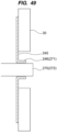
- FIG. 49 is a view showing another embodiment of the second bearing.
- the stationary side bearing body 271 is integrally formed with the bearing supporter 246 of the discharge casing 22.
- the bearing supporter 246 is made of a same bearing material (e.g., ceramic, steel or resin) as the stationary side bearing body 271.
- the motor pump MP may include the first impeller 1A having the same structure as the impeller 1 according to the embodiments shown in FIGS. 35 to 39 or the first impeller 1A according to the embodiments shown in FIGS. 40 to 42 .
- the motor pump MP may include the first impeller 1A having the same structure as the impeller 1 according to the embodiments shown in FIGS. 1 to 34 .
- the embodiments shown in FIGS. 1 to 49 may be combined whenever possible.
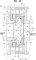
- FIG. 50 is a view showing a side plate provided in the motor pump according to the embodiment described above.
- the motor pump MP may further include a side plate 300 that restricts an outflow of the liquid (liquid to be handled) pressurized by the impeller 1 to the discharge port 322.
- the side plate 300 has a disc shape and is fixed to the return vane 30.
- the side plate 300 is arranged between the main plate 10 of the impeller 1 and the return vane 30. A part of the liquid pressurized by the impeller 1 flows through the gap between the side plate 300 and the discharge casing 22 via the return vane 30, and is discharged from the outlet 322a. The other part of the liquid pressurized by the impeller 1 flows into the gap between the side plate 300 and the main plate 10 of the impeller 1.
- FIG. 51 is a view showing another embodiment of the side plate.
- the side plate 300 may have an opening 300a formed in the center thereof.
- the liquid that has flowed into the gap between the side plate 300 and the main plate 10 may remain in the gap between the side plate 300 and the main plate 10.
- the opening 300a in the side plate 300 a circulating flow of the liquid is formed between the gap between the side plate 300 and the discharge casing 22 and the gap between the side plate 300 and the impeller 1. Therefore, the liquid existing between the side plate 300 and the impeller 1 flows into the discharge casing 22 side, and a heat generation in the liquid is prevented and the temperature of the liquid is maintained at a constant level. Furthermore, the opening 300a can serve to discharge air contained in the remaining liquid to the discharge casing 22 side.
- the opening 300a of the side plate 300 is a single opening formed on the center line CL, but the number of openings 300a is not limited to this embodiment.
- the side plate 300 may have a plurality of openings 300a to an extent that the movement of the impeller 1 toward the discharge casing 22 is restricted.
- the opening 300a does not necessarily need to be formed on the center line CL as long as it can form the circulating flow of the liquid.
- the side plate 300 may have at least one opening 300a arranged concentrically around the center line CL.
- the shape of the opening 300a is also not particularly limited, and may have a circular shape or a polygonal shape (e.g., a triangular shape or a quadrangular shape). Similarly, a size (i.e., area) of the opening 300a is not particularly limited as long as the movement of the side plate 300 toward the discharge casing 22 is restricted.
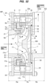
- FIG. 52 is a view showing another embodiment of the motor pump.
- the motor pump MP includes the discharge casing 22 having a discharge port 322 extending in a vertical direction perpendicular to the direction of the centerline CL of the motor pump MP.
- the discharge port 322 has an upwardly opening outlet 322a, and the inlet 21a and the outlet 322a are orthogonal to each other.
- the motor pump MP is a so-called end-top motor pump, in which the inlet 21a and the outlet 322a are orthogonal.
- the motor pump MP has a compact structure.
- the motor pump MP it may not be possible to install the motor pump MP with a structure in which the inlet 21a and the outlet 22a are arranged in a straight line. Even in such cases, the end-top type motor pump MP can be installed.
- the motor pump MP can be installed in any installation environment.
- the motor pump MP may further include the side plate 300 that restricts the outflow of the liquid (liquid to be handled) pressurized by the impeller 1 to the discharge port 322.
- the side plate 300 can be applied to the end-top type motor pump MP.
- the side plate 300 may also have the opening 300a (see FIG. 51 ).
- the invention is applicable to a motor pump.
Landscapes
- Engineering & Computer Science (AREA)
- Mechanical Engineering (AREA)
- General Engineering & Computer Science (AREA)
- Physics & Mathematics (AREA)
- Fluid Mechanics (AREA)
- Structures Of Non-Positive Displacement Pumps (AREA)
Applications Claiming Priority (2)
| Application Number | Priority Date | Filing Date | Title |
|---|---|---|---|
| JP2021143964 | 2021-09-03 | ||
| PCT/JP2022/021701 WO2023032366A1 (fr) | 2021-09-03 | 2022-05-27 | Motopompe |
Publications (2)
| Publication Number | Publication Date |
|---|---|
| EP4397864A1 true EP4397864A1 (fr) | 2024-07-10 |
| EP4397864A4 EP4397864A4 (fr) | 2025-08-06 |
Family
ID=85411153
Family Applications (1)
| Application Number | Title | Priority Date | Filing Date |
|---|---|---|---|
| EP22863954.8A Pending EP4397864A4 (fr) | 2021-09-03 | 2022-05-27 | Motopompe |
Country Status (6)
| Country | Link |
|---|---|
| EP (1) | EP4397864A4 (fr) |
| JP (1) | JPWO2023032366A1 (fr) |
| KR (1) | KR20240051237A (fr) |
| CN (1) | CN117881896A (fr) |
| TW (1) | TW202311631A (fr) |
| WO (1) | WO2023032366A1 (fr) |
Cited By (1)
| Publication number | Priority date | Publication date | Assignee | Title |
|---|---|---|---|---|
| WO2025252528A1 (fr) * | 2024-06-04 | 2025-12-11 | Valeo Systemes Thermiques | Pompe centrifuge à efficacité améliorée |
Family Cites Families (13)
| Publication number | Priority date | Publication date | Assignee | Title |
|---|---|---|---|---|
| DE69013761T2 (de) * | 1989-06-05 | 1995-03-16 | Ebara Corp | Magnetpumpe. |
| JPH06315245A (ja) * | 1993-04-27 | 1994-11-08 | Japan Servo Co Ltd | キャンドモータポンプの永久磁石回転子 |
| JP4059416B2 (ja) | 1999-04-20 | 2008-03-12 | 英男 林 | 一体型モータポンプ |
| US6254361B1 (en) * | 1999-07-29 | 2001-07-03 | Itt Manufacturing Enterprises, Inc. | Shaftless canned rotor inline pipe pump |
| JP2001241396A (ja) * | 2000-02-29 | 2001-09-07 | Ebara Corp | 多段モータポンプ |
| JP4774574B2 (ja) * | 2000-04-17 | 2011-09-14 | パナソニック電工株式会社 | ポンプ |
| JP2002138986A (ja) * | 2000-11-07 | 2002-05-17 | Ebara Corp | モータポンプ |
| DE10251461A1 (de) * | 2002-11-05 | 2004-05-13 | BSH Bosch und Siemens Hausgeräte GmbH | Elektrisch angetriebene Pumpe |
| JP2008215307A (ja) * | 2007-03-07 | 2008-09-18 | Ikutoku Gakuen | 一体型モータポンプ |
| DE102017203833A1 (de) * | 2017-03-08 | 2018-09-13 | Mahle International Gmbh | Flüssigkeitspumpe |
| CN107605755A (zh) * | 2017-09-14 | 2018-01-19 | 合肥恒大江海泵业股份有限公司 | 一种叶轮内置式混流潜水电泵 |
| JP6948198B2 (ja) * | 2017-09-22 | 2021-10-13 | 株式会社荏原製作所 | 遠心ポンプ |
| CN110873061B (zh) * | 2018-08-29 | 2023-08-01 | 广东德昌电机有限公司 | 泵体及用于泵体的转子组件的制造方法 |
-
2022
- 2022-05-27 EP EP22863954.8A patent/EP4397864A4/fr active Pending
- 2022-05-27 KR KR1020247010460A patent/KR20240051237A/ko active Pending
- 2022-05-27 JP JP2023545082A patent/JPWO2023032366A1/ja active Pending
- 2022-05-27 CN CN202280058522.XA patent/CN117881896A/zh active Pending
- 2022-05-27 WO PCT/JP2022/021701 patent/WO2023032366A1/fr not_active Ceased
- 2022-06-23 TW TW111123338A patent/TW202311631A/zh unknown
Cited By (1)
| Publication number | Priority date | Publication date | Assignee | Title |
|---|---|---|---|---|
| WO2025252528A1 (fr) * | 2024-06-04 | 2025-12-11 | Valeo Systemes Thermiques | Pompe centrifuge à efficacité améliorée |
Also Published As
| Publication number | Publication date |
|---|---|
| KR20240051237A (ko) | 2024-04-19 |
| CN117881896A (zh) | 2024-04-12 |
| JPWO2023032366A1 (fr) | 2023-03-09 |
| EP4397864A4 (fr) | 2025-08-06 |
| TW202311631A (zh) | 2023-03-16 |
| WO2023032366A1 (fr) | 2023-03-09 |
Similar Documents
| Publication | Publication Date | Title |
|---|---|---|
| EP4397865A1 (fr) | Motopompe | |
| EP4477893A1 (fr) | Unité pompe | |
| CN110676967B (zh) | 带有支撑端盘的密封管式马达 | |
| EP1580434B1 (fr) | Pompe électrique | |
| EP4317695A1 (fr) | Motopompe, unité de pompe et procédé de réglage d'équilibre pour roue de motopompe | |
| US6023838A (en) | Method of producing motor casing | |
| US7649299B2 (en) | Rotating electrical machine and alternating-current generator | |
| CN110957842B (zh) | 旋转电机 | |
| CN111416463B (zh) | 设置有冷却结构的旋转电机 | |
| GB2469901A (en) | Canned motor pump | |
| US12074492B2 (en) | Stator of an electrical coolant drive, contact device for a stator and electrical coolant drive | |
| CN115217765B (zh) | 离心泵组件 | |
| EP4397864A1 (fr) | Motopompe | |
| US8807920B2 (en) | Pump assembly | |
| RU2419948C1 (ru) | Усовершенствование конструкции экранированного электронасоса (варианты) | |
| TWI921552B (zh) | 馬達泵浦 | |
| JP2026074298A (ja) | モータポンプ、ポンプユニット | |
| CN111486097A (zh) | 泵装置 | |
| CN117098919A (zh) | 马达泵、泵单元及马达泵的叶轮的平衡调整方法 |
Legal Events
| Date | Code | Title | Description |
|---|---|---|---|
| STAA | Information on the status of an ep patent application or granted ep patent |
Free format text: STATUS: THE INTERNATIONAL PUBLICATION HAS BEEN MADE |
|
| PUAI | Public reference made under article 153(3) epc to a published international application that has entered the european phase |
Free format text: ORIGINAL CODE: 0009012 |
|
| STAA | Information on the status of an ep patent application or granted ep patent |
Free format text: STATUS: REQUEST FOR EXAMINATION WAS MADE |
|
| 17P | Request for examination filed |
Effective date: 20240326 |
|
| AK | Designated contracting states |
Kind code of ref document: A1 Designated state(s): AL AT BE BG CH CY CZ DE DK EE ES FI FR GB GR HR HU IE IS IT LI LT LU LV MC MK MT NL NO PL PT RO RS SE SI SK SM TR |
|
| DAV | Request for validation of the european patent (deleted) | ||
| DAX | Request for extension of the european patent (deleted) | ||
| A4 | Supplementary search report drawn up and despatched |
Effective date: 20250707 |
|
| RIC1 | Information provided on ipc code assigned before grant |
Ipc: F04D 13/06 20060101AFI20250701BHEP Ipc: F04D 29/22 20060101ALI20250701BHEP |