EP4397875A1 - Dispositif de palier magnétique et pompe à vide - Google Patents
Dispositif de palier magnétique et pompe à vide Download PDFInfo
- Publication number
- EP4397875A1 EP4397875A1 EP22864351.6A EP22864351A EP4397875A1 EP 4397875 A1 EP4397875 A1 EP 4397875A1 EP 22864351 A EP22864351 A EP 22864351A EP 4397875 A1 EP4397875 A1 EP 4397875A1
- Authority
- EP
- European Patent Office
- Prior art keywords
- abnormality
- magnetic bearing
- control
- control parameter
- bearing device
- Prior art date
- Legal status (The legal status is an assumption and is not a legal conclusion. Google has not performed a legal analysis and makes no representation as to the accuracy of the status listed.)
- Pending
Links
Images


Classifications
-
- F—MECHANICAL ENGINEERING; LIGHTING; HEATING; WEAPONS; BLASTING
- F04—POSITIVE - DISPLACEMENT MACHINES FOR LIQUIDS; PUMPS FOR LIQUIDS OR ELASTIC FLUIDS
- F04D—NON-POSITIVE-DISPLACEMENT PUMPS
- F04D19/00—Axial-flow pumps
- F04D19/02—Multi-stage pumps
- F04D19/04—Multi-stage pumps specially adapted to the production of a high vacuum, e.g. molecular pumps
- F04D19/048—Multi-stage pumps specially adapted to the production of a high vacuum, e.g. molecular pumps comprising magnetic bearings
-
- F—MECHANICAL ENGINEERING; LIGHTING; HEATING; WEAPONS; BLASTING
- F04—POSITIVE - DISPLACEMENT MACHINES FOR LIQUIDS; PUMPS FOR LIQUIDS OR ELASTIC FLUIDS
- F04D—NON-POSITIVE-DISPLACEMENT PUMPS
- F04D19/00—Axial-flow pumps
- F04D19/02—Multi-stage pumps
- F04D19/04—Multi-stage pumps specially adapted to the production of a high vacuum, e.g. molecular pumps
- F04D19/042—Turbomolecular vacuum pumps
-
- F—MECHANICAL ENGINEERING; LIGHTING; HEATING; WEAPONS; BLASTING
- F04—POSITIVE - DISPLACEMENT MACHINES FOR LIQUIDS; PUMPS FOR LIQUIDS OR ELASTIC FLUIDS
- F04D—NON-POSITIVE-DISPLACEMENT PUMPS
- F04D19/00—Axial-flow pumps
- F04D19/02—Multi-stage pumps
- F04D19/04—Multi-stage pumps specially adapted to the production of a high vacuum, e.g. molecular pumps
-
- F—MECHANICAL ENGINEERING; LIGHTING; HEATING; WEAPONS; BLASTING
- F04—POSITIVE - DISPLACEMENT MACHINES FOR LIQUIDS; PUMPS FOR LIQUIDS OR ELASTIC FLUIDS
- F04D—NON-POSITIVE-DISPLACEMENT PUMPS
- F04D27/00—Control, e.g. regulation, of pumps, pumping installations or pumping systems specially adapted for elastic fluids
- F04D27/004—Control, e.g. regulation, of pumps, pumping installations or pumping systems specially adapted for elastic fluids by varying driving speed
-
- F—MECHANICAL ENGINEERING; LIGHTING; HEATING; WEAPONS; BLASTING
- F04—POSITIVE - DISPLACEMENT MACHINES FOR LIQUIDS; PUMPS FOR LIQUIDS OR ELASTIC FLUIDS
- F04D—NON-POSITIVE-DISPLACEMENT PUMPS
- F04D27/00—Control, e.g. regulation, of pumps, pumping installations or pumping systems specially adapted for elastic fluids
- F04D27/008—Stop safety or alarm devices, e.g. stop-and-go control; Disposition of check-valves
-
- F—MECHANICAL ENGINEERING; LIGHTING; HEATING; WEAPONS; BLASTING
- F04—POSITIVE - DISPLACEMENT MACHINES FOR LIQUIDS; PUMPS FOR LIQUIDS OR ELASTIC FLUIDS
- F04D—NON-POSITIVE-DISPLACEMENT PUMPS
- F04D29/00—Details, component parts, or accessories
- F04D29/05—Shafts or bearings, or assemblies thereof, specially adapted for elastic fluid pumps
- F04D29/056—Bearings
- F04D29/058—Bearings magnetic; electromagnetic
-
- F—MECHANICAL ENGINEERING; LIGHTING; HEATING; WEAPONS; BLASTING
- F16—ENGINEERING ELEMENTS AND UNITS; GENERAL MEASURES FOR PRODUCING AND MAINTAINING EFFECTIVE FUNCTIONING OF MACHINES OR INSTALLATIONS; THERMAL INSULATION IN GENERAL
- F16C—SHAFTS; FLEXIBLE SHAFTS; ELEMENTS OR CRANKSHAFT MECHANISMS; ROTARY BODIES OTHER THAN GEARING ELEMENTS; BEARINGS
- F16C32/00—Bearings not otherwise provided for
- F16C32/04—Bearings not otherwise provided for using magnetic or electric supporting means
- F16C32/0406—Magnetic bearings
- F16C32/044—Active magnetic bearings
- F16C32/0442—Active magnetic bearings with devices affected by abnormal, undesired or non-standard conditions such as shock-load, power outage, start-up or touchdown
-
- F—MECHANICAL ENGINEERING; LIGHTING; HEATING; WEAPONS; BLASTING
- F16—ENGINEERING ELEMENTS AND UNITS; GENERAL MEASURES FOR PRODUCING AND MAINTAINING EFFECTIVE FUNCTIONING OF MACHINES OR INSTALLATIONS; THERMAL INSULATION IN GENERAL
- F16C—SHAFTS; FLEXIBLE SHAFTS; ELEMENTS OR CRANKSHAFT MECHANISMS; ROTARY BODIES OTHER THAN GEARING ELEMENTS; BEARINGS
- F16C32/00—Bearings not otherwise provided for
- F16C32/04—Bearings not otherwise provided for using magnetic or electric supporting means
- F16C32/0406—Magnetic bearings
- F16C32/044—Active magnetic bearings
- F16C32/0444—Details of devices to control the actuation of the electromagnets
- F16C32/0446—Determination of the actual position of the moving member, e.g. details of sensors
-
- F—MECHANICAL ENGINEERING; LIGHTING; HEATING; WEAPONS; BLASTING
- F16—ENGINEERING ELEMENTS AND UNITS; GENERAL MEASURES FOR PRODUCING AND MAINTAINING EFFECTIVE FUNCTIONING OF MACHINES OR INSTALLATIONS; THERMAL INSULATION IN GENERAL
- F16C—SHAFTS; FLEXIBLE SHAFTS; ELEMENTS OR CRANKSHAFT MECHANISMS; ROTARY BODIES OTHER THAN GEARING ELEMENTS; BEARINGS
- F16C32/00—Bearings not otherwise provided for
- F16C32/04—Bearings not otherwise provided for using magnetic or electric supporting means
- F16C32/0406—Magnetic bearings
- F16C32/044—Active magnetic bearings
- F16C32/0444—Details of devices to control the actuation of the electromagnets
- F16C32/0451—Details of controllers, i.e. the units determining the power to be supplied, e.g. comparing elements, feedback arrangements with P.I.D. control
- F16C32/0453—Details of controllers, i.e. the units determining the power to be supplied, e.g. comparing elements, feedback arrangements with P.I.D. control for controlling two axes, i.e. combined control of x-axis and y-axis
-
- F—MECHANICAL ENGINEERING; LIGHTING; HEATING; WEAPONS; BLASTING
- F16—ENGINEERING ELEMENTS AND UNITS; GENERAL MEASURES FOR PRODUCING AND MAINTAINING EFFECTIVE FUNCTIONING OF MACHINES OR INSTALLATIONS; THERMAL INSULATION IN GENERAL
- F16C—SHAFTS; FLEXIBLE SHAFTS; ELEMENTS OR CRANKSHAFT MECHANISMS; ROTARY BODIES OTHER THAN GEARING ELEMENTS; BEARINGS
- F16C32/00—Bearings not otherwise provided for
- F16C32/04—Bearings not otherwise provided for using magnetic or electric supporting means
- F16C32/0406—Magnetic bearings
- F16C32/044—Active magnetic bearings
- F16C32/0444—Details of devices to control the actuation of the electromagnets
- F16C32/0451—Details of controllers, i.e. the units determining the power to be supplied, e.g. comparing elements, feedback arrangements with P.I.D. control
- F16C32/0455—Details of controllers, i.e. the units determining the power to be supplied, e.g. comparing elements, feedback arrangements with P.I.D. control including digital signal processing [DSP] and analog/digital conversion [A/D, D/A]
-
- F—MECHANICAL ENGINEERING; LIGHTING; HEATING; WEAPONS; BLASTING
- F16—ENGINEERING ELEMENTS AND UNITS; GENERAL MEASURES FOR PRODUCING AND MAINTAINING EFFECTIVE FUNCTIONING OF MACHINES OR INSTALLATIONS; THERMAL INSULATION IN GENERAL
- F16C—SHAFTS; FLEXIBLE SHAFTS; ELEMENTS OR CRANKSHAFT MECHANISMS; ROTARY BODIES OTHER THAN GEARING ELEMENTS; BEARINGS
- F16C32/00—Bearings not otherwise provided for
- F16C32/04—Bearings not otherwise provided for using magnetic or electric supporting means
- F16C32/0406—Magnetic bearings
- F16C32/044—Active magnetic bearings
- F16C32/0474—Active magnetic bearings for rotary movement
- F16C32/0489—Active magnetic bearings for rotary movement with active support of five degrees of freedom, e.g. two radial magnetic bearings combined with an axial bearing
-
- F—MECHANICAL ENGINEERING; LIGHTING; HEATING; WEAPONS; BLASTING
- F16—ENGINEERING ELEMENTS AND UNITS; GENERAL MEASURES FOR PRODUCING AND MAINTAINING EFFECTIVE FUNCTIONING OF MACHINES OR INSTALLATIONS; THERMAL INSULATION IN GENERAL
- F16C—SHAFTS; FLEXIBLE SHAFTS; ELEMENTS OR CRANKSHAFT MECHANISMS; ROTARY BODIES OTHER THAN GEARING ELEMENTS; BEARINGS
- F16C2360/00—Engines or pumps
- F16C2360/44—Centrifugal pumps
- F16C2360/45—Turbo-molecular pumps
Definitions
- the present invention relates to a magnetic bearing device and a vacuum pump, and particularly relates to a magnetic bearing device and a vacuum pump that are capable of recovering from an abnormal state such as oscillation safely, with high operating efficiency, in a levitation system using a magnetic bearing and that have high reliability with low false detection of abnormalities.
- a vacuum pump is used for implementing exhaustion for such a chamber, and particularly a turbomolecular pump, i.e., a type of vacuum pump, is frequently used from the perspective of low residual gas, easy maintenance, and the like.
- a semiconductor manufacturing process includes a large of number of processes in which various process gases are caused to act on the semiconductor substrate, and the turbomolecular pump is used not only to evacuate the chamber but also to exhaust these process gases from the chamber.
- turbomolecular pumps are also used in equipment such as electron microscopes to create a high degree of vacuum in the environment inside the chamber of an electron microscope and the like in order to prevent refraction of the electron beam caused by the presence of dust and the like.
- the turbomolecular pump is equipped with a magnetic bearing device to control the magnetic levitation of the rotating body.
- the position of the rotating body needs to be controlled at high speed and with a strong force when the rotating body passes through a resonance point during accelerated operation or when a noise occurs during constant speed operation.
- the position control of the rotating body is performed by feedback control.
- the feedback control when vibration occurs in the rotating body, the vibration is suppressed by the magnetic force synchronized with the vibration. Consequently, an oscillation phenomenon may occur when the design of the feedback control is inappropriate. In addition to this oscillation phenomenon, various abnormalities such as noise, vibrations, and power failure may occur in the turbomolecular pump depending on the environment.
- PTL 1 discloses an example in which, when the automatic reset is enabled, the magnetic bearing device is reset by restarting and the operation is continued to restore the normal state, but when the automatic reset is disabled, the operation of the magnetic bearing device is stopped.
- PTL 4 discloses a method for setting a filter that can be stably controlled even if such a change occurs.
- the pump in a case where the pump is operated in a state near the stability limit due to improper settings of the control parameters of the magnetic bearing device, an abnormality such as oscillation is likely to occur due to a slight environmental change. In such a state, the pump is susceptible to manufacturing variations and the installation environment.
- noise may be generated as a result of the correction. This noise may then be determined as an abnormal state by the magnetic bearing device. However, this is temporary and resolved spontaneously without the need for action. Therefore, it does not have to be determined as abnormal.
- the present invention (claim 1) is a magnetic bearing device including a rotating body, a magnetic bearing that magnetically supports the rotating body in a floating manner in air, and a magnetic bearing controller that controls the magnetic bearing, the magnetic bearing device further including: a first abnormality detection means for detecting an abnormality of control by the magnetic bearing controller on a basis of a predetermined first abnormality condition; a control parameter correction means for correcting a control parameter of the magnetic bearing controller while continuing an operation of the magnetic bearing device when the first abnormality detection means detects the abnormality of the control; a second abnormality detection means for detecting the abnormality of the control by the magnetic bearing controller on a basis of a predetermined second abnormality condition having a larger degree of abnormality than the first abnormality condition; and a stopping means for stopping the operation of the magnetic bearing device when the second abnormality detection means detects the abnormality of the control.
- the present invention (claim 4) is the invention of the magnetic bearing device, wherein the control parameter correction means further includes, after the first abnormality resolution determination step determines that the state of the abnormality of the control determined based on the first abnormality condition has been resolved, a stability evaluation step of evaluating whether or not the operation of the magnetic bearing device that employs the control parameter saved in the first abnormality resolution determination step has a predetermined stability where the abnormality of the control by the magnetic bearing controller does not occur, and wherein the control parameter of the magnetic bearing controller is further corrected when the stability evaluation step evaluates that the stability is not sufficient.
- the first abnormality is resolved, and the occurrence of a further abnormality can be prevented. Therefore, the operation efficiency improves and the safety improves.
- the present invention (claim 5) is the invention of the magnetic bearing device, wherein the stability evaluation step performs the evaluation using at least one of application of a vibration signal, an increase in a control gain of the magnetic bearing controller, and a decrease in the control gain of the magnetic bearing controller.
- the present invention (claim 6) is the invention of the magnetic bearing device, wherein, when the abnormality of the control determined based on the second abnormality condition is detected in the process of correcting the control parameter by the control parameter correction means, the control parameter correction means applies the control parameter set in the past to stop the operation of the magnetic bearing device.
- the present invention is the invention of the magnetic bearing device, wherein when the first abnormality detection means detects the abnormality of the control, the control parameter correction means stops revolution speed control of the rotating body and corrects the control parameter of the magnetic bearing controller in a state in which the rotating body runs freely.
- the vacuum pump there are many natural vibration modes in which, for example, a rotating body is provided, and oscillation is likely occur due to the natural vibration, abnormalities due to changes in the state of the system can be dealt with by readjusting the control parameters.
- the operation efficiency of the vacuum pump can be improved by shortening the time it takes until recovery.
- the present invention is a magnetic bearing device including a rotating body, a magnetic bearing that magnetically supports the rotating body in a floating manner in air, and a magnetic bearing controller that controls the magnetic bearing, the magnetic bearing device being configured to further include an abnormality detection means for detecting an abnormality of control by the magnetic bearing controller based on a predetermined abnormality condition, a control parameter correction means for correcting a control parameter of the magnetic bearing controller, a predetermined range of areas including a point on a time axis, a revolution speed axis, or a frequency axis where the control parameter correction means corrects the control parameter, and a mitigating means for mitigating the predetermined abnormality condition in the predetermined range of areas.
- an abnormality detection means for detecting an abnormality of control by the magnetic bearing controller based on a predetermined abnormality condition
- a control parameter correction means for correcting a control parameter of the magnetic bearing controller, a predetermined range of areas including a point on a time axis, a revolution speed axis, or
- the abnormality of the control by the magnetic bearing controller is detected based on a predetermined abnormality condition.
- noise tends to occur in the control system.
- this noise is not caused by an abnormality, it should not be detected erroneously.
- the predetermined abnormality condition is mitigated in the predetermined range of areas.
- control parameter correction is not performed, the abnormality is determined based on an abnormality condition that is not mitigated, enabling prompt detection of abnormality.
- the present invention (claim 15) is the invention of the magnetic bearing device, wherein the predetermined range of areas consists of a front area in front of the point and a rear area behind the point, the rear area being larger than the front area.
- the area behind the point on the time axis, the revolution speed axis, or the frequency axis where control parameter correction is performed is set to be larger than the front area in terms of time, revolution speed, or frequency.
- the present invention is an invention of a vacuum pump, characterized in including the magnetic bearing device according to claim 13 or 14 mounted therein.
- the upper radial sensors 107 are configured to detect a radial displacement of the rotor shaft 113, that is, the rotating body 103 fixed thereto, and send the radial displacement to a central processing unit (CPU) of a control device, not shown.
- CPU central processing unit
- the central arithmetic processing device is equipped with the function of a magnetic bearing controller.
- a compensation circuit having a PID adjustment function generates an excitation control command signal of the upper radial electromagnets 104 based on a position signal detected by the upper radial sensors 107, and a magnetic bearing inverter, not shown, excites and controls the upper radial electromagnets 104 based on this excitation control command signal, thereby adjusting an upper radial position of the rotor shaft 113.
- the rotor shaft 113 is made of, for instance, a high magnetic permeability material (such as steel, stainless steel) and configured to be attracted by the magnetic force of the upper radial electromagnets 104. Such adjustment is performed in an X-axis direction and a Y-axis direction independently.
- a lower radial electromagnet 105 and a lower radial sensor 108 are arranged in the same manner as the upper radial electromagnets 104 and the upper radial sensors 107, and a lower radial position of the rotor shaft 113 is adjusted in the same manner as the upper radial position of the same.
- axial electromagnets 106A and 106B are arranged so as to vertically sandwich a discshaped metal disc 111 provided at the lower part of the rotor shaft 113.
- the metal disc 111 is made of a high magnetic permeability material such as iron.
- An axial sensor 109 is configured to detect an axial displacement of the rotor shaft 113 and send an axial position signal thereof to the central processing unit (CPU) of the control device, not shown.
- the exhaust gas from the chamber, not shown is sucked in through the inlet port 101 by the actions of the rotor blades 102 and the stator blades 123.
- the rotation speed of the rotor blades 102 is usually 20,000 rpm to 90,000 rpm, and the peripheral speed at the tips of the rotor blades 102 reaches 200 m/s to 400 m/s.
- the exhaust gas sucked in through the inlet port 101 passes between the rotor blades 102 and the stator blades 123 and is transferred to the base portion 129.
- the central processing unit detects a second abnormality based on a predetermined determination criterion.
- This second abnormality is an abnormality that cannot be dealt with by readjusting the magnetic bearing control parameter, or an abnormality that should stop the operation immediately in some circumstances. That is, the second abnormality refers to a situation where the oscillation has a larger amplitude than the oscillation of the first abnormality, or where the rotating body 103 comes into contact with the touchdown bearing 141 and the touchdown bearing 143, or where the time set in this contact state is up, or where a DC link voltage rises or falls abnormally, or where other abnormalities occur.
- the determination criterion for the second abnormality may be set when it is assumed that the rotating body 103 comes into contact with the touchdown bearing 141 and the touchdown bearing 143 or when it is confirmed by a contact detection sensor, not shown, that the rotating body 103 is in contact with the touchdown bearing 141 and the touchdown bearing 143.
- One contact or a specified number of contacts may be set.
- the determination criterion for the second abnormality may be set when the first abnormality has not been resolved even after the control parameter readjustment is performed a predetermined number of times.
- the determination criterion for the second abnormality may be set when the first abnormality has not been resolved even after a lapse of a predetermined time.
- the determination criterion for the second abnormality may also be set when an abnormality that cannot be dealt with by the control parameters such as a power failure, a disconnection, or other failure detection, is detected.
- step 23 the filter a and the filter b, which are the control parameters set in the time series number 3, are stored in the central processing unit (CPU).
- step 25 the central processing unit (CPU) adds a filter d in addition to the filter a and the filter b (changing step), and executes the magnetic bearing control with this control parameter (control step).
- step 27 the central processing unit (CPU) determines whether or not the state of the first abnormality has improved (state improvement determination step). That is, in the time series number 4, it is determined whether or not the state of the first abnormality has improved as compared with that obtained one step before. In the time series number 4 of FIG. 5 , the central processing unit (CPU) determined that the first abnormality did not improve. At this time, the processing proceeds to step 31, and the central processing unit (CPU) returns the control parameters to the filter a and the filter b, which are the values obtained one step before. Subsequently, the processing returns to step 23 again. Therefore, the filters that are set at the end of the time series number 4 in FIG. 5 remain the filter a and the filter b.
- step 23 the filter a and the filter b, which are the control parameters set in the time series number 4, are stored in the central processing unit (CPU).
- step 25 the central processing unit (CPU) adds a filter e in addition to the filter a and the filter b (changing step), and executes the magnetic bearing control with this control parameter (control step).
- step 41 that was being processed concurrently, the central processing unit (CPU) detects the second abnormality. Therefore, the processing forcibly proceeds to step 43, and the control parameters are returned to the previous values by the central processing unit (CPU). That is, in the case of FIG. 5 , the filter a and the filter b are set as the best parameters at the time, the processing proceeds to step 45, and the operation is stopped.
- step 41 be executed as frequently as possible independently of the readjustment step following the detection of the first abnormality.
- FIG. 6 since the time series numbers 0 to 4 of FIG. 6 are the same as those of FIG. 5 , the description thereof will be omitted accordingly.
- step 41 the central processing unit (CPU) detects the second abnormality in step 41. Therefore, the process forcibly proceeds to step 43, and the control parameters are returned to the previous values. That is, in the case of FIG. 6 , the control parameters are returned to the initial values by the central processing unit (CPU). Proceeding to step 45, with the filters remaining at the initial values, the operation of the pump is stopped.
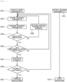
- step 51 the central processing unit (CPU) detects the first abnormality based on the predetermined determination criterion described above.
- step 71 of FIG. 7 the central processing unit (CPU) detects the second abnormality based on the predetermined determination criterion described above.
- step 51 If the central processing unit (CPU) detects the first abnormality in step 51 but does not detect the second abnormality in step 71, first, the control parameters are stored in the central processing unit (CPU) in step 52. Thereafter, in step 53, the central processing unit (CPU) changes the control parameters (changing step) and executes the magnetic bearing control with the control parameters (control step)
- step 54 the central processing unit (CPU) determines whether or not the state of the first abnormality has improved (state improvement determination step). If the state of the first abnormality has not improved, the central processing unit (CPU) restores the control parameters in step 56 and then returns to step 52. On the other hand, if the state of the first abnormality has improved, the control parameter at this point is kept, the processing proceeds to step 55, and the central processing unit (CPU) determines whether or not the first abnormality has been resolved (state improvement determination step). If the first abnormality has not been resolved, the processing returns to step 52.
- step 55 if it is determined in step 55 that the first abnormality has been resolved, the processing proceeds to step 57, and the stability evaluation is performed by the central processing unit (CPU (stability evaluation step).
- This stability evaluation is performed by, for example, the central processing unit (CPU) generating a vibration signal and sending it to the magnetic bearing device, and the central processing unit (CPU) measuring the transfer function thereof.
- the stability evaluation is performed by the central processing unit (CPU) generating a vibration signal and sending it to the magnetic bearing device, and the central processing unit (CPU) measuring the step response or impulse response.
- the vibration signal is, for example, a step signal, an impulse signal, white noise, a single frequency sine wave, a frequency swept sine wave, a swept sign, or the like.
- the central processing unit (CPU) may increase or decrease the magnetic bearing control gain to determine the stability based on whether or not the first abnormality or the second abnormality occurs.
- the measurement of the transfer function, the measurement of the step response, and the measurement of the impulse response may be combined with the increase and decrease of the magnetic bearing control gain.
- the vibration signal may be generated by the central processing unit (CPU) or may be input from an external device.
- the first abnormality is resolved, and the occurrence of a further abnormality can be prevented. Therefore, the operation efficiency improves and the safety improves.
- step 71 In a case where the central processing unit (CPU) detects the second abnormality in step 71, the operation of the pump is stopped in step 73.
- CPU central processing unit
- the central processing unit (CPU) detects the first abnormality at the point indicated by "X1" in the diagram when the pump is started, the central processing unit (CPU) executes readjustment while controlling the deceleration of the rotating body 103.
- the deceleration control means a control that gives a torque that lowers the revolution speed, such as regenerative operation of the motor, output of the generator, and the like.
- the central processing unit (CPU) accelerates the rotating body 103.
- the central processing unit performs readjustment during the deceleration operation of the rotating body 103
- the revolution speed at the time of readjustment is smaller than that at the time of abnormality detection.
- the lower the revolution speed the smaller the damage caused at the time of touchdown; the rotation speed equal to or lower than a predetermined revolution speed can be ignored. Therefore, it is possible to reduce the damage that occurs when an abnormality increases during the readjustment and the touchdown occurs. Accordingly, the safety improves.
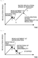
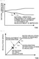
- the central processing unit (CPU) detects the first abnormality at the point indicated by "X8" in the diagram during operation at the rated revolution speed
- the central processing unit (CPU) starts readjustment before the revolution speed reaches zero even when decelerating the rotating body or causing the rotating body to run freely.
- the central processing unit (CPU) confirms that the first abnormality has been resolved at the point indicated by "X9”
- the central processing unit (CPU) accelerates the rotating body 103.
- the time it takes to reach the rated revolution speed at the point indicated by "X10” can be saved, resulting in quick recovery to the rated revolution speed.
- FIG. 13 is almost the same as the operation example of FIG. 9 , but the difference is that, when the central processing unit (CPU) detects the first abnormality at the point indicated by "X1" in the diagram, the central processing unit (CPU) performs readjustment while causing the rotating body 103 to run freely, as in FIG. 12 .
- the central processing unit (CPU) detects the second abnormality at the point indicated by "X12"
- the central processing unit (CPU) stops the rotating body 103. As a result, the safety of the pump can be ensured.
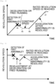
- the central processing unit (CPU) detects the first abnormality at the point indicated by "X1" in the diagram
- the central processing unit (CPU) performs readjustment while performing constant speed control until the point indicated by "X13" in the diagram is reached.
- the state when an abnormality occurs can be maintained. This makes it possible to efficiently figure out the cause.
- the central processing unit (CPU) confirms that the first abnormality has been resolved at the point indicated by "X13"
- the central processing unit (CPU) accelerates the rotating body 103.
- the time it takes to reach the rated revolution speed can be saved at the point indicated by "X14,” resulting in quick recovery to the rated revolution speed.
- FIG. 16 shows the characteristics of a change in the natural frequency of the rotating body 103 caused by the gyro effect in the operation example of FIG. 14 .
- the turbomolecular pump 100 includes the rotor blades 102, wherein an abnormality such as oscillation due to its natural vibration is likely to occur.
- the central processing unit CPU
- the central processing unit performs readjustment while performing constant speed control from the point indicated by "X16" in the diagram to the point indicated by "X17". That is, since the natural frequency is constant during the readjustment, the readjustment accuracy improves. Therefore, the operation efficiency of the pump can be improved.
- the central processing unit (CPU) detects the first abnormality at the point indicated by "X1" in the diagram, the central processing unit (CPU) performs readjustment while controlling the acceleration of the rotating body 103. Subsequently, once the central processing unit (CPU) confirms that the first abnormality has been resolved at the point indicated by "X18", the central processing unit (CPU) continues to accelerate the rotating body 103. Since the central processing unit (CPU) executes the readjustment during the acceleration of the rotating body and continues accelerate the rotating body immediately after the abnormality is resolved, the rated revolution speed can be reached most quickly.
- the processing methods described in the respective operation examples described above be used properly according to the operating state immediately before the detection of the first abnormality. For example, when the immediately preceding operating state indicates acceleration, it is better to accelerate the rotating body in order to reach the rating quickly, so the central processing unit (CPU) selects readjustment during the acceleration operation. Further, if the immediately preceding operating state indicates deceleration, there is no point in accelerating the rotating body, so the central processing unit (CPU) selects readjustment while continuing to decelerate the rotating body.
- step 81 of FIG. 19 the operation is performed under abnormality detection conditions for a normal state.
- the operation is performed under the abnormality detection conditions for the normal state from time 0 to time 11.
- the abnormality detection conditions for the normal state are, for example, the conditions set to detect the first abnormal state and the second abnormal state in the case of the example described above.
- step 83 the central processing unit (CPU) determines that the conditions for changing a predetermined control parameter have been met. This determination means that, for example, the central processing unit (CPU) determines that changing a control parameter such as adding the filter a to the central processing unit (CPU) as shown in the time series number 1 in FIG. 4 is ready to be carried out.
- step 85 the abnormality detection conditions are switched to a mitigated state at time t1 shown in FIG. 20 .
- the reason for switching the abnormality detection conditions to the mitigated state is to mitigate the abnormality detection conditions so that the central processing unit (CPU) does not detect an abnormality based on noise that is generated as a result of the processing for changing a control parameter.
- the central processing unit when detecting the first abnormal state and the second abnormal state described above, for example the central processing unit (CPU) is stopped from detecting an abnormality using the abnormality detection means.
- step 87 a control parameter is changed at time t0 shown in FIG. 20 .
- the filter a is added to the central processing unit (CPU) at the time series number 1 in the example shown in FIG. 4 .
- step 89 a predetermined period of time from time t0 to time t2 shown in FIG. 20 is waited.
- step 91 the abnormality detection conditions are switched to the normal state at time t2 shown in FIG. 20 , and the operation is continued in step 93.
- Examples of cases where control parameters are changed include (1) when the filter is changed according to a predetermined revolution speed, (2) when the first abnormality is detected and the control parameter correction means of the central processing unit (CPU) corrects a control parameter, and (3) when a control parameter correction command is input to the magnetic bearing controller via external communication.
- CPU central processing unit
- CPU central processing unit
- Time t0 and time t10 and the revolution speed ⁇ 0 correspond to the points on the time axis, the revolution speed axis, and the frequency axis where control parameters are corrected, and the range from time t1 to t2 and the range from the revolution speed ⁇ 1 to ⁇ 2 correspond to the predetermined range of areas.
- the range from time t1 to t0 and the range from the revolution speed ⁇ 1 to ⁇ 0 correspond to the front area
- the range from time t0 to t2 and the range from the revolution speed ⁇ 0 to ⁇ 2 correspond to the rear area.
Landscapes
- Engineering & Computer Science (AREA)
- General Engineering & Computer Science (AREA)
- Mechanical Engineering (AREA)
- Physics & Mathematics (AREA)
- Electromagnetism (AREA)
- Signal Processing (AREA)
- Magnetic Bearings And Hydrostatic Bearings (AREA)
Applications Claiming Priority (3)
| Application Number | Priority Date | Filing Date | Title |
|---|---|---|---|
| JP2021140302 | 2021-08-30 | ||
| JP2022125790A JP2023035884A (ja) | 2021-08-30 | 2022-08-05 | 磁気軸受装置及び真空ポンプ |
| PCT/JP2022/031777 WO2023032767A1 (fr) | 2021-08-30 | 2022-08-23 | Dispositif de palier magnétique et pompe à vide |
Publications (2)
| Publication Number | Publication Date |
|---|---|
| EP4397875A1 true EP4397875A1 (fr) | 2024-07-10 |
| EP4397875A4 EP4397875A4 (fr) | 2025-11-12 |
Family
ID=85412521
Family Applications (1)
| Application Number | Title | Priority Date | Filing Date |
|---|---|---|---|
| EP22864351.6A Pending EP4397875A4 (fr) | 2021-08-30 | 2022-08-23 | Dispositif de palier magnétique et pompe à vide |
Country Status (5)
| Country | Link |
|---|---|
| US (1) | US20240337267A1 (fr) |
| EP (1) | EP4397875A4 (fr) |
| KR (1) | KR20240052741A (fr) |
| IL (1) | IL310336A (fr) |
| WO (1) | WO2023032767A1 (fr) |
Families Citing this family (1)
| Publication number | Priority date | Publication date | Assignee | Title |
|---|---|---|---|---|
| JP2025136764A (ja) * | 2024-03-08 | 2025-09-19 | エドワーズ株式会社 | 磁気軸受装置、ターボ分子ポンプおよび磁気軸受部の制御方法 |
Family Cites Families (11)
| Publication number | Priority date | Publication date | Assignee | Title |
|---|---|---|---|---|
| JP2601487Y2 (ja) * | 1993-04-21 | 1999-11-22 | セイコー精機株式会社 | 磁気軸受装置 |
| JP3591111B2 (ja) | 1996-02-29 | 2004-11-17 | 松下電器産業株式会社 | 磁気軸受制御装置 |
| JP3546144B2 (ja) | 1998-10-01 | 2004-07-21 | 三菱重工業株式会社 | ターボ分子ポンプとその保護動作方法 |
| JP2001293637A (ja) | 2000-04-12 | 2001-10-23 | Matsushita Electric Ind Co Ltd | 磁気軸受装置 |
| JP4374777B2 (ja) | 2000-12-21 | 2009-12-02 | パナソニック株式会社 | 磁気軸受の制御装置およびこれを用いた磁気軸受スピンドル装置 |
| JP2006145006A (ja) | 2004-11-24 | 2006-06-08 | Jtekt Corp | 磁気軸受装置 |
| JP4929208B2 (ja) * | 2008-02-29 | 2012-05-09 | 三菱重工業株式会社 | 磁気軸受装置 |
| JP6131602B2 (ja) * | 2013-01-17 | 2017-05-24 | 株式会社島津製作所 | 磁気軸受装置および真空ポンプ |
| JP6728821B2 (ja) * | 2016-03-18 | 2020-07-22 | 株式会社島津製作所 | 磁気軸受式真空ポンプ |
| JP7155531B2 (ja) * | 2018-02-14 | 2022-10-19 | 株式会社島津製作所 | 磁気浮上制御装置および真空ポンプ |
| JP6999485B2 (ja) * | 2018-04-20 | 2022-01-18 | エドワーズ株式会社 | 真空ポンプ、及び真空ポンプの制御装置 |
-
2022
- 2022-08-23 WO PCT/JP2022/031777 patent/WO2023032767A1/fr not_active Ceased
- 2022-08-23 KR KR1020247000630A patent/KR20240052741A/ko active Pending
- 2022-08-23 US US18/293,940 patent/US20240337267A1/en active Pending
- 2022-08-23 IL IL310336A patent/IL310336A/en unknown
- 2022-08-23 EP EP22864351.6A patent/EP4397875A4/fr active Pending
Also Published As
| Publication number | Publication date |
|---|---|
| IL310336A (en) | 2024-03-01 |
| KR20240052741A (ko) | 2024-04-23 |
| TW202325986A (zh) | 2023-07-01 |
| EP4397875A4 (fr) | 2025-11-12 |
| WO2023032767A1 (fr) | 2023-03-09 |
| US20240337267A1 (en) | 2024-10-10 |
Similar Documents
| Publication | Publication Date | Title |
|---|---|---|
| US9077214B2 (en) | Magnetic bearing control device and exhaust pump having magnetic bearing control device | |
| EP3677785B1 (fr) | Pompe à vide | |
| US6736593B2 (en) | Protective device for a turbo molecular pump and method of protecting a turbo molecular pump | |
| EP1046821B1 (fr) | Dispositif de protection pour paliers magnétiques et pompe turbo-moléculair | |
| US10590955B2 (en) | Turbo-molecular pump | |
| US20170268519A1 (en) | Magnetic levitation vacuum pump | |
| EP4397875A1 (fr) | Dispositif de palier magnétique et pompe à vide | |
| JP2005083316A (ja) | モータ制御システム及び該モータ制御システムを搭載した真空ポンプ | |
| CN114341501A (zh) | 真空泵及真空泵的附属单元 | |
| EP4397874A1 (fr) | Dispositif de palier magnétique et pompe à vide | |
| JP2023035884A (ja) | 磁気軸受装置及び真空ポンプ | |
| EP3681032B1 (fr) | Pompe à vide et dispositif de commande de moteur | |
| TWI921596B (zh) | 磁性軸承裝置及真空泵 | |
| CN117795213A (zh) | 磁轴承装置及真空泵 | |
| JP5255752B2 (ja) | ターボ分子ポンプ | |
| JP2006083924A (ja) | 磁気軸受制御装置 | |
| JPH04325797A (ja) | 磁気軸受式ターボ分子ポンプ | |
| JP2006112490A (ja) | 磁気軸受装置 |
Legal Events
| Date | Code | Title | Description |
|---|---|---|---|
| STAA | Information on the status of an ep patent application or granted ep patent |
Free format text: STATUS: THE INTERNATIONAL PUBLICATION HAS BEEN MADE |
|
| PUAI | Public reference made under article 153(3) epc to a published international application that has entered the european phase |
Free format text: ORIGINAL CODE: 0009012 |
|
| STAA | Information on the status of an ep patent application or granted ep patent |
Free format text: STATUS: REQUEST FOR EXAMINATION WAS MADE |
|
| 17P | Request for examination filed |
Effective date: 20240124 |
|
| AK | Designated contracting states |
Kind code of ref document: A1 Designated state(s): AL AT BE BG CH CY CZ DE DK EE ES FI FR GB GR HR HU IE IS IT LI LT LU LV MC MK MT NL NO PL PT RO RS SE SI SK SM TR |
|
| DAV | Request for validation of the european patent (deleted) | ||
| DAX | Request for extension of the european patent (deleted) | ||
| REG | Reference to a national code |
Ref country code: DE Ref legal event code: R079 Free format text: PREVIOUS MAIN CLASS: F16C0032040000 Ipc: F04D0019040000 |
|
| RIC1 | Information provided on ipc code assigned before grant |
Ipc: F04D 19/04 20060101AFI20250714BHEP Ipc: F16C 32/04 20060101ALI20250714BHEP Ipc: F04D 27/00 20060101ALI20250714BHEP Ipc: F04D 29/058 20060101ALI20250714BHEP |
|
| A4 | Supplementary search report drawn up and despatched |
Effective date: 20251013 |
|
| RIC1 | Information provided on ipc code assigned before grant |
Ipc: F04D 19/04 20060101AFI20251007BHEP Ipc: F16C 32/04 20060101ALI20251007BHEP Ipc: F04D 27/00 20060101ALI20251007BHEP Ipc: F04D 29/058 20060101ALI20251007BHEP |