EP4397933A2 - Vorrichtung und verfahren zur speicherung von energie als wärme - Google Patents
Vorrichtung und verfahren zur speicherung von energie als wärme Download PDFInfo
- Publication number
- EP4397933A2 EP4397933A2 EP24177176.5A EP24177176A EP4397933A2 EP 4397933 A2 EP4397933 A2 EP 4397933A2 EP 24177176 A EP24177176 A EP 24177176A EP 4397933 A2 EP4397933 A2 EP 4397933A2
- Authority
- EP
- European Patent Office
- Prior art keywords
- storage media
- thermal storage
- working fluid
- heat exchanger
- chamber
- Prior art date
- Legal status (The legal status is an assumption and is not a legal conclusion. Google has not performed a legal analysis and makes no representation as to the accuracy of the status listed.)
- Pending
Links
Images







Classifications
-
- F—MECHANICAL ENGINEERING; LIGHTING; HEATING; WEAPONS; BLASTING
- F01—MACHINES OR ENGINES IN GENERAL; ENGINE PLANTS IN GENERAL; STEAM ENGINES
- F01K—STEAM ENGINE PLANTS; STEAM ACCUMULATORS; ENGINE PLANTS NOT OTHERWISE PROVIDED FOR; ENGINES USING SPECIAL WORKING FLUIDS OR CYCLES
- F01K3/00—Plants characterised by the use of steam or heat accumulators, or intermediate steam heaters, therein
- F01K3/12—Plants characterised by the use of steam or heat accumulators, or intermediate steam heaters, therein having two or more accumulators
-
- F—MECHANICAL ENGINEERING; LIGHTING; HEATING; WEAPONS; BLASTING
- F02—COMBUSTION ENGINES; HOT-GAS OR COMBUSTION-PRODUCT ENGINE PLANTS
- F02C—GAS-TURBINE PLANTS; AIR INTAKES FOR JET-PROPULSION PLANTS; CONTROLLING FUEL SUPPLY IN AIR-BREATHING JET-PROPULSION PLANTS
- F02C1/00—Gas-turbine plants characterised by the use of hot gases or unheated pressurised gases, as the working fluid
- F02C1/04—Gas-turbine plants characterised by the use of hot gases or unheated pressurised gases, as the working fluid the working fluid being heated indirectly
-
- F—MECHANICAL ENGINEERING; LIGHTING; HEATING; WEAPONS; BLASTING
- F02—COMBUSTION ENGINES; HOT-GAS OR COMBUSTION-PRODUCT ENGINE PLANTS
- F02C—GAS-TURBINE PLANTS; AIR INTAKES FOR JET-PROPULSION PLANTS; CONTROLLING FUEL SUPPLY IN AIR-BREATHING JET-PROPULSION PLANTS
- F02C1/00—Gas-turbine plants characterised by the use of hot gases or unheated pressurised gases, as the working fluid
- F02C1/04—Gas-turbine plants characterised by the use of hot gases or unheated pressurised gases, as the working fluid the working fluid being heated indirectly
- F02C1/10—Closed cycles
-
- F—MECHANICAL ENGINEERING; LIGHTING; HEATING; WEAPONS; BLASTING
- F25—REFRIGERATION OR COOLING; COMBINED HEATING AND REFRIGERATION SYSTEMS; HEAT PUMP SYSTEMS; MANUFACTURE OR STORAGE OF ICE; LIQUEFACTION SOLIDIFICATION OF GASES
- F25B—REFRIGERATION MACHINES, PLANTS OR SYSTEMS; COMBINED HEATING AND REFRIGERATION SYSTEMS; HEAT PUMP SYSTEMS
- F25B13/00—Compression machines, plants or systems, with reversible cycle
-
- F—MECHANICAL ENGINEERING; LIGHTING; HEATING; WEAPONS; BLASTING
- F28—HEAT EXCHANGE IN GENERAL
- F28D—HEAT-EXCHANGE APPARATUS, NOT PROVIDED FOR IN ANOTHER SUBCLASS, IN WHICH THE HEAT-EXCHANGE MEDIA DO NOT COME INTO DIRECT CONTACT
- F28D20/00—Heat storage plants or apparatus in general; Regenerative heat-exchange apparatus not covered by groups F28D17/00 or F28D19/00
- F28D20/0056—Heat storage plants or apparatus in general; Regenerative heat-exchange apparatus not covered by groups F28D17/00 or F28D19/00 using solid heat storage material
-
- F—MECHANICAL ENGINEERING; LIGHTING; HEATING; WEAPONS; BLASTING
- F25—REFRIGERATION OR COOLING; COMBINED HEATING AND REFRIGERATION SYSTEMS; HEAT PUMP SYSTEMS; MANUFACTURE OR STORAGE OF ICE; LIQUEFACTION SOLIDIFICATION OF GASES
- F25B—REFRIGERATION MACHINES, PLANTS OR SYSTEMS; COMBINED HEATING AND REFRIGERATION SYSTEMS; HEAT PUMP SYSTEMS
- F25B2313/00—Compression machines, plants or systems with reversible cycle not otherwise provided for
- F25B2313/001—Compression machines, plants or systems with reversible cycle not otherwise provided for with two or more accumulators
-
- F—MECHANICAL ENGINEERING; LIGHTING; HEATING; WEAPONS; BLASTING
- F28—HEAT EXCHANGE IN GENERAL
- F28C—HEAT-EXCHANGE APPARATUS, NOT PROVIDED FOR IN ANOTHER SUBCLASS, IN WHICH THE HEAT-EXCHANGE MEDIA COME INTO DIRECT CONTACT WITHOUT CHEMICAL INTERACTION
- F28C3/00—Other direct-contact heat-exchange apparatus
- F28C3/10—Other direct-contact heat-exchange apparatus one heat-exchange medium at least being a fluent solid, e.g. a particulate material
- F28C3/12—Other direct-contact heat-exchange apparatus one heat-exchange medium at least being a fluent solid, e.g. a particulate material the heat-exchange medium being a particulate material and a gas, vapour, or liquid
-
- Y—GENERAL TAGGING OF NEW TECHNOLOGICAL DEVELOPMENTS; GENERAL TAGGING OF CROSS-SECTIONAL TECHNOLOGIES SPANNING OVER SEVERAL SECTIONS OF THE IPC; TECHNICAL SUBJECTS COVERED BY FORMER USPC CROSS-REFERENCE ART COLLECTIONS [XRACs] AND DIGESTS
- Y02—TECHNOLOGIES OR APPLICATIONS FOR MITIGATION OR ADAPTATION AGAINST CLIMATE CHANGE
- Y02E—REDUCTION OF GREENHOUSE GAS [GHG] EMISSIONS, RELATED TO ENERGY GENERATION, TRANSMISSION OR DISTRIBUTION
- Y02E60/00—Enabling technologies; Technologies with a potential or indirect contribution to GHG emissions mitigation
- Y02E60/14—Thermal energy storage
Definitions
- a prime mover driven by an energy source (for example an electricity supply) drives a compressor for working fluid within a working fluid circuit.
- An expander coupled to the compressor, expands working fluid in the circuit and also drives the compressor.
- a working fluid (whether a gas or a liquid) is pressurised and heated adiabatically by the action of the compressor and a first (high temperature/high pressure side) heat exchanger transfers energy from the working fluid to a heat store, being a mass of a material with a suitably high heat capacity, which heats up.
- This step is typically isobaric and the pressurised working fluid which has given up heat is then expanded and cooled adiabatically by the action of the expander.
- a second (low temperature/low pressure side) heat exchanger transfers energy from a cold store, being a further mass of material with a suitably high heat capacity, which is thereby cooled.
- This heat exchange step is again typically isobaric and the warmed working fluid is then recirculated to the compressor. Energy from the energy source is thereby used to transfer heat energy from the cold store to the heat store, thereby storing energy.
- the thermodynamic process is effectively operated in reverse and a power take-off (such as an electricity generator) coupled to the compressor and the expander outputs recovered (regenerated) energy.
- Some embodiments of the invention make use of thermal storage media which is moved, in use, from a first container to a second container, through the hot side or cold side heat exchanger as appropriate.
- the transportation of thermal storage media enables, losses in the energy storage and recovery processes to be minimised and the size of the heat exchanger to be reduced.
- the invention seeks to provide apparatus with a good storage and recovery efficiency, and a good capacity, for a given size.
- Typical heat exchangers use indirect contact between a gas and a thermal storage medium, through the wall of a heat exchanger, increasing the size of the heat exchanger and reducing efficiency and power throughput.
- Gas to liquid direct contact heat exchangers and known but have poor efficiency once the gas flow rate exceeds the flooding point. If they are operated below this point then they have good efficiency but a low rating.
- the present invention employs a direct contact heat exchanger in which heat flows directly between a gaseous working fluid and a solid thermal storage media. This arrangement has the potential to be efficient at high rates of energy storage or use, but transporting the thermal storage media into or out of highly pressurised thermal storage media containers presents a substantial technical challenge. Practical challenges mean that existing devices require separate apparatus (e.g. separate heat exchangers and/or containers for thermal storage media) for heat energy storage and heat energy recovery.
- the present invention seeks to address the above and other problems with pumped heat energy storage systems. Some aspects of the invention address technical problems relating particularly to heat exchangers useful for such apparatus. Some aspects of the invention address technical problems relating to moving solid thermal storage media across a pressure gradient, into or out of a direct contact heat exchanger.
- a pumped heat energy storage apparatus comprising a working fluid circulation pathway retaining working fluid and a heat exchanger, the heat exchanger having a heat exchange chamber configured to bring thermal storage media into direct contact with working fluid in the working fluid circulation pathway to thereby exchange heat energy between the working fluid and the thermal storage media, wherein the working fluid is typically a gas within the heat exchange chamber and wherein the thermal storage media is a solid, wherein the heat exchanger is configured to cause received thermal storage media to be moved into and out of (typically through) the heat exchange chamber, and wherein the heat exchanger is reversible to transfer heat energy from the working fluid to the thermal storage media or vice versa in alternative first and second operating modes.
- a method of operating a pumped heat energy storage apparatus comprising a working fluid circulation pathway retaining working fluid and a heat exchanger, the method comprising the step of receiving thermal storage media into a heat exchange chamber of the heat exchanger, contacting the thermal storage media with typically gaseous working fluid within the heat exchange chamber, and then outputting the thermal storage media from the heat exchange chamber, wherein the heat exchanger is reversible to transfer heat energy from the working fluid to the thermal storage media or vice versa in alternative first and second operating modes.
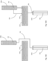
- the thermal storage media passes through the heat exchange chamber in a first direction and in the second operating mode the thermal storage media passes through the heat exchange chamber in the opposite direction.
- the working fluid circulation path comprises a high pressure side and a low pressure side, with a said heat exchanger in the high pressure side (functioning as a high temperature heat exchanger).
- the working fluid circulation path comprises a further heat exchanger (a low temperature heat exchanger) in the low pressure side.
- the heat exchanger may be a high pressure side (high temperature) heat exchanger.
- the heat exchanger may be a low pressure side (low temperature) heat exchanger.
- the further heat exchanger may also be reversible to transfer heat energy from the working fluid to the thermal storage media or vice versa in alternative first and second operating modes of the further heat exchanger, wherein in the first operating mode of the further heat exchanger the working fluid cools thermal storage media and in the second operating mode of the further heat exchanger, thermal storage media warms working fluid.
- Other optional features of the heat exchanger described herein may also be features of the further heat exchanger.
- the further heat exchanger may be a corresponding heat exchanger.
- the working fluid is typically a gas within the heat exchange chamber.
- the working fluid may remain a gas around the whole of the working fluid circulation pathway. However, it may be that the working fluid is a gas within the heat exchange chamber but a liquid at another portion of the working fluid circulation pathway.
- the working fluid circulation pathway comprises a high temperature heat exchanger (which is the abovementioned heat exchanger) and also a low temperature heat exchanger (which may be the further heat exchanger) and the working fluid is a gas within the high temperature heat exchanger and is at least in part a liquid within the low temperature heat exchanger. This might occur if, for example, the working fluid is carbon dioxide.
- the working fluid may be a liquid within the heat exchange chamber.
- a compressor and an expander we refer to machines which compress or expand a fluid respectively.
- a compressor we include a pump and by an expander we include a motor.
- the working fluid is a liquid in one or both of the compressor or the expander in which case the working fluid is pumped by the compressor or expanded by the motor.
- the compressor and expander are typically positive displacement machines.
- the compressor and expander may be different parts of the same machine, for example they may comprise different groups of one or more working chambers (e.g. cylinders) of a fluid working machine.
- the apparatus is configured so that in a first operating mode, the thermal storage media is received from a first media store and moved through the heat exchange chamber in a first direction. It may be that in the second operating mode the thermal storage media is moved through the heat exchange chamber in a second direction which is the reverse of the first direction. It may be that in the second operating mode the thermal storage media is returned to the first media store. It may be that in the first operating mode the thermal storage media is output to a second media store. It may be that in the second operating mode the thermal storage media is received from the second media store. It may be that the direction of movement of the thermal storage media through the heat exchange chamber reverses when the apparatus switched from the first operating mode to the second operating mode.
- the apparatus is configured so that in a first operating mode, the thermal storage media is received from a first media store and input into the heat exchanger and that in the second operating mode, the thermal storage media is output from the heat exchanger (and typically also returned to the first media store) on a last in first out basis, at least initially when the apparatus changes from the first operating mode to the second operating mode. It may be that the apparatus is configured so that in the first operating mode, the thermal storage media is output from the heat exchanger and transferred to a second media store, and that in the second operating mode, the thermal storage media is received from the second media store into the heat exchanger on a last out first in basis.
- the heat exchange apparatus is configured to transport the thermal storage media through the heat exchange chamber using a motor. This contrasts with the use of gravity. It may be that the heat exchange apparatus is configured to transport thermal storage media through the heat exchange chamber at a slope of less than ⁇ 5°, relative to horizontal, and typically substantially horizontal. Typically, the majority of the volume of the heat exchange chamber is defined by a pipe which extends at a slope of less than ⁇ 5°, relative to horizontal, and typically substantially horizontal.
- the apparatus is configured so that in the first operating mode working fluid flows through the heat exchange chamber along one or more first paths and in the second operating mode working fluid flow through the heat exchange chamber in the opposite direction along the one or more first paths.
- the compressor and expander swap functions (the machine which is a compressor in the first operating modes functions as an expander in the second operating mode and the machine which is an expander in the first operating mode functions as a compressor in the second operating mode).
- the working fluid follows the same path, in opposite directions, between the same two working machines (one functioning as a compressor in the first operating mode and an expander in the second operating mode, and the other functioning as an expander in the first operating mode and a compressor in the second operating mode.
- the compressor and expander have rotatable shafts which are coupled (for example are parts of the same shaft).
- the working fluid circulation pathway has a high pressure side and a low pressure side. These typically correspond to high temperature sides and low temperature sides. That being said, it may be that the temperatures in the high pressure and low pressure sides are highly variable in time and along the length of the high and low pressure sides of the working fluid circulation pathway. For example, the temperature at opposite ends of a heat exchanger in the working fluid circulation pathway is typically very different.
- first and second fluid working machines divide the working fluid circulation pathway into a high pressure side and a low pressure side. By this we refer to the relative pressure of the working fluid in the working fluid circulation pathway in use.
- first and second fluid working machines have rotatable shafts which are coupled (for example are parts of the same shaft), and are also coupled to the prime mover and a power take off (which may optionally be the prime mover in the first operating mode and function as the power take off in the second operating mode, for example an electrical motor also operable as a generator).
- a power take off which may optionally be the prime mover in the first operating mode and function as the power take off in the second operating mode, for example an electrical motor also operable as a generator.
- the controller controls the low and high pressure valves to cause each working chamber to undergo either an inactive cycle with no net displacement of working fluid or an active cycle with a net displacement of working fluid.
- the controller controls the low and high pressure valves to cause each working chamber to carry out either compressor cycles (which lead working fluid being received from the low pressure manifold and output at a higher pressure and temperature to the high pressure manifold) or expander cycles (which lead to working fluid being received from the high pressure manifold and output at a lower pressure and temperature to the low pressure manifold).
- the thermal storage media is particulate.
- the thermal storage media may comprise or be formed as particles which may be spherical.
- the particles may have a diameter in range of 5 to 25mm, for example 8 to 15mm.
- the residency time of the thermal storage media within the heat exchange chamber may be in the range of 2 to 20 minutes, for example 3 to 8 minutes.
- the heat exchange chamber is at a higher pressure than the media store (during operation).
- thermal storage media is transferred into the at least one transfer chamber from a media store, the volume of the at least one working chamber is decreased to compress working fluid in the at least one transfer chamber and then the thermal storage media (and at least some of the compressed working fluid) is transferred from the at least one transfer chamber to the heat exchange chamber.
- the at least one working chamber is sealed from the at least one transfer chamber after the step of compressing the working fluid and before the step of transferring the thermal storage media and at least some of the compressed working fluid from the transfer chamber to the heat exchange chamber.
- the at least one working chamber is sealed from the at least one transfer chamber after the step of expanding the working fluid and before the step of transferring the thermal storage media (and at least some of the compressed working fluid) from the transfer chamber to the media store.
- the at least one transfer chamber and typically also the at least one working chamber are connected to the heat exchange chamber and working fluid is allowed to circulate therebetween.
- the volume of the at least one transfer chamber is reduced to displace thermal storage media therein into the heat exchange chamber (for example by the movement of a piston).
- thermal storage media is displaced into the heat exchange chamber
- the volume of the at least one working chamber increases and there is a net flow of working fluid from the heat exchange chamber into the at least one working chamber.
- pressurised working fluid is displaced into the at least one working chamber, where it can be used to recover energy.
- the method comprises disconnecting the at least one working chamber from the heat exchange chamber and then expanding the working fluid remaining within the at least one working chamber.
- energy is recovered from this expansion (from the work done by the working fluid on the at least one working chamber (e.g. on a piston)).
- the volume of the at least one working chamber is increased to expand working fluid in the at least one transfer chamber.
- working fluid received typically with thermal storage media
- the heat exchanger is used to recover energy by work done in expanding the at least one working chamber.
- this takes place with the at least one working chamber connected to the at least one transfer chamber but not to the heat exchanger.
- the thermal storage media and expanded working fluid are typically transferred to the media store.
- the method typically includes the step of receiving the thermal storage media into the at least one transfer chamber from the heat exchange chamber.
- the at least one transfer chamber is located below the end of the heat exchange chamber from where thermal storage media is received.
- the transfer of thermal storage media from the heat exchange chamber into the at least one thermal transfer chamber can be gravity fed.
- the method may comprise the step of at the at least one working chamber decreasing in volume and compressing working fluid (typically while the at least one working chamber is sealed).
- the at least one working chamber has pressurised working fluid to transfer to the heat exchange chamber.
- at least one working chamber is sealed after the step of expanding working fluid in the at least one transfer chamber.
- thermal storage media in the at least one transfer chamber is then transferred to the thermal media store.
- the thermal storage media may fall out of the at least one transfer chamber, for example through a port which is exposed when a piston within the at least one transfer chamber is at the lowest end of its travel.
- the thermal storage media is raised by a conveyor (e.g. an auger) to the thermal media store (which is typically higher than the heat exchange chamber), typically from below the heat exchange chamber.
- working fluid is pressurised and introduced into the heat exchange chamber periodically and/or continuously. This maintains the mass of working fluid circulating in the working fluid circulation pathway.
- the pressure and/or rate of introduction may be varied to achieve a fixed or variable target mass of working fluid in the working fluid circulation pathway.
- At least one transfer chamber may be located above the heat exchange chamber and the apparatus may further comprises a valve which when actuated allows thermal storage media within the at least one transfer chamber to fall into the heat exchange chamber by gravity.
- the said at least one transfer chamber may comprise a piston cylinder in which the piston moves downward to reduce the volume of the chamber and upward to increase the volume of the chamber.
- the at least one transfer chamber may be configured to receive thermal storage media when the piston is above a threshold position in the cylinder.
- thermal storage media is either being loaded into or unloaded from the heat exchange chamber at one end of heat exchange chamber (typically, while being unloaded or loaded respectively at the other end of the heat exchange chamber) and so this enables one or more chambers which are not currently required to transfer thermal storage media to be used as the one or more working chambers.
- the method also comprises receiving the thermal storage media along with gas (typically within which the thermal storage media has been stored), and separating the received gas from the thermal storage media, prior to bringing the thermal storage media into direct contact with the working fluid, while restricting the ingress of received gas into the working fluid circulation pathway.
- Said received gas may be returned to a container for thermal storage media, such as the container from which the thermal storage media was received.
- the method comprises the step of displacing the gas (e.g. received gas or working fluid) from the thermal storage media with a liquid.
- the gas e.g. received gas or working fluid
- Liquids are much less compressible than gases. They can displace gas and thereby enable gas which is in contact with the thermal storage media to be separated from the thermal storage media.
- the liquid may comprise, or essential comprise, a liquid polysiloxane (a silicone fluid), for example Syltherm 800 . (Syltherm is a trade mark of Dow Corning Corporation).
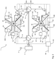
- the high temperature heat exchanger is thereby functioning in its first operating mode, transferring heat to glass beads.
- the glass beads After travelling through the horizontal heat exchange chamber the glass beads fall into pit 84 and are lifted through conduit 48 to the air lock 36 and then through conduit 50 to the top of hopper 30B where it is stored.
- the hopper is thermally insulated and heat can be retained for a long period of time.
- glass beads are moved from ambient hopper 30D through conduit 58 and the low temperature air lock and conduit 60 to the second end of the low temperature heat exchanger.
- the auger within the low temperature heat exchanger moves the beads along the length of the heat exchanger, in direction 92, again in contra flow to the cooled working fluid received from the expander.
- the low temperature heat exchanger functions in its first operating mode, cooling glass beads.
- the beads fall into the pit at the end of the heat exchanger and are lifted through conduit 68, passed through the air lock and lifted through conduit 64 to the top of hopper 30C.
- the compressor and expander may each be electrically commutated fluid working machines comprising a plurality of working chambers having a volume which varies cyclically with rotation of the rotatable shaft (e.g. piston cylinders)
- the apparatus may have additional modes. For example, once fully charged, with the beads in high temperature storage hopper 30B and/or low temperature storage hopper 30C at predetermine threshold temperatures, the machine may temporarily shut down, retaining the hot and cold beads for later use when required, or operate in an idle mode in which the working fluid continues to be circulated at a relatively low flow rate but without the beads being further moved, or moved only slowly. This enables the machine to switch to energy recovery/electricity generation quickly when required.
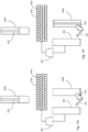
- Working fluid on the high pressure side flows through conduit 20 to switchable valve 11B where, in the energy storage mode, it is directed to dedicated expander 7B, where it is expanded and transferred to the low pressure side via switchable valve 11D. Beads are moved through the hoppers and heat exchangers as per Figure 1 .
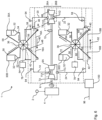
- the apparatus has a high pressure side 226A and low pressure side 226B (which can alternatively or in addition be seen as high and low temperature sides).
- the working fluid circulation pathway 208, 214, 216A, 220, 210, 222, 216B, 224, 208 includes a high pressure conduit 214 which extends from the first fluid working machine 208 to a heat exchanger chamber 216A of high pressure side heat exchanger 218A (high temperature heat exchanger) and then to the high pressure side of the second fluid working machine 210 through second high pressure conduit 220.
- the arrows on the conduits show the direction of working fluid flow during energy storage and that direction reverses during energy recovery.
- the apparatus further comprises high pressure and low pressure side thermal media storage paths.
- hopper 230A stores ambient temperature beads 232 (thermal storage media)
- hopper 230B stored heated beads
- hopper 230C stores cooled beads
- hopper 230D stores ambient temperature beads.
- the beads move through the high pressure heat exchange chamber 216A from a first end 270 to second end 272 and through the low pressure heat exchange chamber 216B from a first end 274 to a second end 276, i.e. in the opposite direction to the direction of flow of working fluid through the heat exchange chambers.
- low and high pressure refer to pressure relative to each other.
- both the low and high pressure sides of the working fluid circulation pathway are at greater than atmospheric pressure throughout.
- the speed of rotation of the rotatable shaft may be maintained at above a threshold speed, such that the shaft remains synchronous with the electricity grid, to facilitate a rapid switch to energy recovery/electricity generation (by having the effect of ensuring that decision points to cause working chambers to carry out compressor or expander strokes as required are relatively frequent).
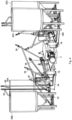
- the loading cylinders 236A, 236B, 236C, 236D function as part lockhoppers used to load beads into the heat exchanger without loss of gaseous working fluid with both the beads and surrounding gaseous working fluid raised to the heat exchanger input pressure. While loading takes place, the corresponding unloading cylinder (244A, 244B, 244C, 244D respectively) functions as a recovery cylinder for the recovery of gaseous working fluid.
- Conduit 235 which conveys beads to the loading cylinders comprises upper and lower knife valves 237A, 237B which are operable by the control to dispense a predetermined volume of beads into the relevant loading chamber.
- a bead valve housing 278 At the base of each loading cylinder a bead valve housing 278 includes a bead valve 242 and bead valve actuator 282 operable under the electronic control of the controller to transport beads (and interstitial working fluid) from the loading chamber into the heat exchanger under gravity.
- a further bead valve housing 278 includes an annular bead valve 242, supported on a bead valve spider 251, and bead valve actuator 282 operable to open the valve through actuation shaft 288 under the electronic control of the controller to transport beads (and interstitial working fluid) from the heat exchanger into the unloading chamber by the action of gravity.
- the apparatus including the media stores is as a whole gastight and so although working fluid may be lost from the working fluid circulation pathway during operation it can be continuously replenished as required.
- Outlet 248 in the unloading cylinders provides a path for beads to pass out of the unloading cylinder when the unloading cylinder piston is sufficiently retracted, whereupon they are returned to the relevant media store through an auger lift.
- a low pressure reservoir 264 maintains a boost pressure.
- bottom dead centre refers to maximum working chamber volume and top dead centre (TDC) refers to minimum working chamber volume although in practice, for the loading cylinder, the piston will be at a lower height at TDC than at BDC.
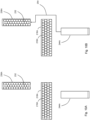
- the loading and unloading cylinders remain connected and the piston of the unloading cylinder travels upwards to top dead centre (TDC, minimum working chamber volume) compressing gas in both the loading and unloading cylinders.
- TDC top dead centre
- the pressure and gas temperature in the loading and unloading cylinders becomes higher than the pressure and gas temperature in the heat exchanger at the end into which the thermal storage media is to be loaded.
- the power consumption by unloading cylinder in compressing the gas amounted to 32.4kW gas averaged over a loading cycle.
- the unloading cylinder and loading cylinder and heat exchanger are all connected to each other.
- the unloading cylinder piston retracts, travelling to BDC while receiving hot glass beads from the heat exchanger while the loading cylinder travels to TDC shunting argon into the heat exchanger, replacing the interstitial gas which would otherwise be lost into the unloading cylinder with the glass beads. No mechanical work is carried out in this step.
- the unloading and loading cylinders are disconnected from the heat exchanger, with the bead valves 242 connecting these cylinders to the heat exchanger both closed, but they remain connected to each other through gas pipework 254.
- Gas remaining in the loading cylinder is expanded adiabatically and the loading cylinder piston travels to BDC while the actuator of the loading cylinder recovers energy from the work done by the expanding gas.
- the power recovered by the loading cylinder piston driven by the expanding gas amounts to 24.58kW, averaged over an unloading cycle.
- the unloading and loading cylinders are disconnected.
- the unloading cylinder is connected to the ambient cylinder 260 through an aperture in the unloading cylinder at around TDC and valves 284. This allows isenthalpic free expansion of gas between the unloading cylinder and the ambient cylinder.
- the loading cylinder piston travels to a position intermediate TDC and BDC, compressing gas in the loading cylinder and returning gas to the heat exchanger through the check valve 286 once pressure in the loading cylinder exceeds the pressure in the heat exchanger.
- the piston does 18.56kW of work in compressing the gas.
- the unloading cylinder is connected to the high temperature media store 230B and the hot glass beads in the unloading cylinder are displaced to the high temperature media store via the action of the unloading cylinder conveyor 252 through outlet 248 which is usually occluded but opened when the unloading cylinder is at BDC.
- the unloading cylinder piston retracts sufficiently far to enable the beads to exit through this outlet and the conveyor 252 rather than the unloading cylinder piston raises the glass beads to the level of the entry to the high temperature media store.
- the loading and unloading cylinders, the heat exchanger and the high temperature media store are all sealed from each other.
- ambient gas from the ambient cylinder 260 is compressed using a multi-stage compressor 262 and injected into the heat exchanger to maintain the required mass of working fluid in the working fluid circuit.
- average power consumption in recompressing ambient gas amounts to 14.88kW over an unloading cycle.
- the unloading procedure then repeats from state A for as long as unloading is required using unloading cylinder 244B.
- the machine may also have adaptations corresponding to the differences between Figures 1 and 6 to use turbomachine compressors and expanders.
- the working fluid is a gas throughout the working fluid circulation pathway, not only in the heat exchanger chambers where it contacts the solid thermal storage media, it is possible for the working fluid to be a liquid in at least part of the working fluid circulation pathway.
- the heat exchangers could instead be operated within a working fluid which is a liquid around the working fluid circulation pathway.
Landscapes
- Engineering & Computer Science (AREA)
- Mechanical Engineering (AREA)
- General Engineering & Computer Science (AREA)
- Chemical & Material Sciences (AREA)
- Combustion & Propulsion (AREA)
- Physics & Mathematics (AREA)
- Thermal Sciences (AREA)
- Engine Equipment That Uses Special Cycles (AREA)
- Central Heating Systems (AREA)
- Compressors, Vaccum Pumps And Other Relevant Systems (AREA)
Applications Claiming Priority (3)
| Application Number | Priority Date | Filing Date | Title |
|---|---|---|---|
| GB201914582A GB201914582D0 (en) | 2019-10-09 | 2019-10-09 | Apparatus and methods for the storage of energy as heat |
| PCT/GB2020/052532 WO2021069929A1 (en) | 2019-10-09 | 2020-10-09 | Apparatus and methods for the storage of energy as heat |
| EP20793103.1A EP4041995B1 (de) | 2019-10-09 | 2020-10-09 | Vorrichtung und verfahren zur speicherung von energie als wärme |
Related Parent Applications (1)
| Application Number | Title | Priority Date | Filing Date |
|---|---|---|---|
| EP20793103.1A Division EP4041995B1 (de) | 2019-10-09 | 2020-10-09 | Vorrichtung und verfahren zur speicherung von energie als wärme |
Publications (2)
| Publication Number | Publication Date |
|---|---|
| EP4397933A2 true EP4397933A2 (de) | 2024-07-10 |
| EP4397933A3 EP4397933A3 (de) | 2024-09-18 |
Family
ID=68541310
Family Applications (2)
| Application Number | Title | Priority Date | Filing Date |
|---|---|---|---|
| EP24177176.5A Pending EP4397933A3 (de) | 2019-10-09 | 2020-10-09 | Vorrichtung und verfahren zur speicherung von energie als wärme |
| EP20793103.1A Active EP4041995B1 (de) | 2019-10-09 | 2020-10-09 | Vorrichtung und verfahren zur speicherung von energie als wärme |
Family Applications After (1)
| Application Number | Title | Priority Date | Filing Date |
|---|---|---|---|
| EP20793103.1A Active EP4041995B1 (de) | 2019-10-09 | 2020-10-09 | Vorrichtung und verfahren zur speicherung von energie als wärme |
Country Status (5)
| Country | Link |
|---|---|
| US (1) | US12123326B2 (de) |
| EP (2) | EP4397933A3 (de) |
| JP (1) | JP2022551711A (de) |
| GB (1) | GB201914582D0 (de) |
| WO (1) | WO2021069929A1 (de) |
Families Citing this family (3)
| Publication number | Priority date | Publication date | Assignee | Title |
|---|---|---|---|---|
| GB202308905D0 (en) | 2023-06-14 | 2023-07-26 | Synchrostor Ltd | Electromagnetic actuator |
| US12103887B1 (en) | 2023-08-21 | 2024-10-01 | Revitri, LLC | Foamed glass beads and process of making same |
| WO2025243055A1 (en) | 2024-05-24 | 2025-11-27 | Synchrostor Limited | In-piston valve assembly |
Citations (4)
| Publication number | Priority date | Publication date | Assignee | Title |
|---|---|---|---|---|
| EP0361927A1 (de) | 1988-09-29 | 1990-04-04 | Artemis Intelligent Power Ltd. | Pumperegelungsverfahren und Tellerventil dafür |
| EP0494236A1 (de) | 1988-09-29 | 1992-07-15 | Univ Edinburgh | Fluidmaschine. |
| EP1537333A1 (de) | 2002-09-12 | 2005-06-08 | Artemis Intelligent Power Ltd. | Fluidarbeitsmaschine und betriebsverfahren |
| WO2009044139A2 (en) | 2007-10-03 | 2009-04-09 | Isentropic Limited | Energy storage |
Family Cites Families (15)
| Publication number | Priority date | Publication date | Assignee | Title |
|---|---|---|---|---|
| DE3533202A1 (de) * | 1985-09-18 | 1987-03-19 | Metallgesellschaft Ag | Verfahren zum fuellen und entleeren eines unter staendigem ueberdruck stehenden behaelters |
| GB9124863D0 (en) * | 1991-11-22 | 1992-01-15 | Beckswift Ltd | Apparatus for effecting heat exchange between a liquid and a particulate material |
| US5924305A (en) * | 1998-01-14 | 1999-07-20 | Hill; Craig | Thermodynamic system and process for producing heat, refrigeration, or work |
| FR2916101B1 (fr) * | 2007-05-11 | 2009-08-21 | Saipem Sa | Installation et procedes de stockage et restitution d'energie electrique |
| FR2922608B1 (fr) * | 2007-10-19 | 2009-12-11 | Saipem Sa | Installation et procede de stockage et restitution d'energie electrique a l'aide d'une unite de compression et detente de gaz a pistons |
| US20120180988A1 (en) | 2011-01-19 | 2012-07-19 | Air Liquide Process & Construction, Inc. | Moving thermal bed to time shift liquifaction and vaporization |
| EP2532843A1 (de) * | 2011-06-09 | 2012-12-12 | ABB Research Ltd. | System zum Speichern von thermoelektrischer Energie mit einer Anordnung zum Speichern von Eis und Verfahren zur Speicherung von thermoelektrischer Energie |
| EP2698506A1 (de) * | 2012-08-17 | 2014-02-19 | ABB Research Ltd. | Elektrothermisches Energiespeichersystem und Verfahren zur Speicherung elektrothermischer Energie |
| WO2014052927A1 (en) * | 2012-09-27 | 2014-04-03 | Gigawatt Day Storage Systems, Inc. | Systems and methods for energy storage and retrieval |
| US10260820B2 (en) * | 2016-06-07 | 2019-04-16 | Dresser-Rand Company | Pumped heat energy storage system using a conveyable solid thermal storage media |
| US10280804B2 (en) * | 2016-12-29 | 2019-05-07 | Malta Inc. | Thermocline arrays |
| US10082104B2 (en) * | 2016-12-30 | 2018-09-25 | X Development Llc | Atmospheric storage and transfer of thermal energy |
| GB201701368D0 (en) * | 2017-01-27 | 2017-03-15 | Univ Newcastle | Heat engine |
| JP2020529550A (ja) * | 2017-08-09 | 2020-10-08 | カプリコーン パワー ピーティーイー リミテッド | 効率的熱回収エンジン |
| US10775111B2 (en) * | 2017-11-29 | 2020-09-15 | Dresser-Rand Company | Pumped heat energy storage system with convey able solid thermal storage media directly thermally coupled to working fluid |
-
2019
- 2019-10-09 GB GB201914582A patent/GB201914582D0/en not_active Ceased
-
2020
- 2020-10-09 JP JP2022521722A patent/JP2022551711A/ja active Pending
- 2020-10-09 WO PCT/GB2020/052532 patent/WO2021069929A1/en not_active Ceased
- 2020-10-09 EP EP24177176.5A patent/EP4397933A3/de active Pending
- 2020-10-09 EP EP20793103.1A patent/EP4041995B1/de active Active
- 2020-10-09 US US17/767,864 patent/US12123326B2/en active Active
Patent Citations (4)
| Publication number | Priority date | Publication date | Assignee | Title |
|---|---|---|---|---|
| EP0361927A1 (de) | 1988-09-29 | 1990-04-04 | Artemis Intelligent Power Ltd. | Pumperegelungsverfahren und Tellerventil dafür |
| EP0494236A1 (de) | 1988-09-29 | 1992-07-15 | Univ Edinburgh | Fluidmaschine. |
| EP1537333A1 (de) | 2002-09-12 | 2005-06-08 | Artemis Intelligent Power Ltd. | Fluidarbeitsmaschine und betriebsverfahren |
| WO2009044139A2 (en) | 2007-10-03 | 2009-04-09 | Isentropic Limited | Energy storage |
Also Published As
| Publication number | Publication date |
|---|---|
| EP4041995A1 (de) | 2022-08-17 |
| EP4041995B1 (de) | 2024-05-22 |
| JP2022551711A (ja) | 2022-12-13 |
| GB201914582D0 (en) | 2019-11-20 |
| US12123326B2 (en) | 2024-10-22 |
| WO2021069929A1 (en) | 2021-04-15 |
| EP4397933A3 (de) | 2024-09-18 |
| US20240084719A1 (en) | 2024-03-14 |
Similar Documents
| Publication | Publication Date | Title |
|---|---|---|
| EP4041995B1 (de) | Vorrichtung und verfahren zur speicherung von energie als wärme | |
| US12292037B2 (en) | Compressed gas energy storage system | |
| US10775111B2 (en) | Pumped heat energy storage system with convey able solid thermal storage media directly thermally coupled to working fluid | |
| KR100857486B1 (ko) | 기계 에너지 생성을 위한 열 엔진 및 방법과, 이들을 적용한 운송 장치 | |
| US9243558B2 (en) | Compressed air energy storage | |
| JP5032665B2 (ja) | ピストン式ガス圧縮膨張ユニットを用いる電気エネルギ蓄積復帰システムおよび電気エネルギ蓄積復帰方法 | |
| US9518786B2 (en) | Heat storage system | |
| CN102869854B (zh) | 改进的热存储系统 | |
| US20120102935A1 (en) | Systems, methods and devices for the management of heat removal within a compression and/or expansion device or system | |
| EP2396589A1 (de) | Anlage zur speicherung und ausgabe von komprimiertem gas | |
| US11976590B2 (en) | Method for producing power with stored energy | |
| CN112424482B (zh) | 用于气体的压缩、膨胀和/或存储的方法、系统和设备 | |
| KR20230117096A (ko) | 극저온 조건에서 캐리어 유체로부터 기계적 에너지를 생성하는 플랜트 | |
| CN115217525B (zh) | 基于氢气等温压缩、膨胀的氢电耦合系统及控制方法 | |
| CN120433457A (zh) | 一种空能净水电栈及应用方法 | |
| US20230358215A1 (en) | Solar power system | |
| EP4720558A1 (de) | Vorrichtung, systeme und verfahren zur handhabung von druckgas | |
| CN117318315A (zh) | 一种基于多级水循环的绝热抽水压缩空气储能装置及方法 |
Legal Events
| Date | Code | Title | Description |
|---|---|---|---|
| PUAI | Public reference made under article 153(3) epc to a published international application that has entered the european phase |
Free format text: ORIGINAL CODE: 0009012 |
|
| STAA | Information on the status of an ep patent application or granted ep patent |
Free format text: STATUS: THE APPLICATION HAS BEEN PUBLISHED |
|
| AC | Divisional application: reference to earlier application |
Ref document number: 4041995 Country of ref document: EP Kind code of ref document: P |
|
| AK | Designated contracting states |
Kind code of ref document: A2 Designated state(s): AL AT BE BG CH CY CZ DE DK EE ES FI FR GB GR HR HU IE IS IT LI LT LU LV MC MK MT NL NO PL PT RO RS SE SI SK SM TR |
|
| REG | Reference to a national code |
Ref country code: DE Ref legal event code: R079 Free format text: PREVIOUS MAIN CLASS: F28D0020000000 Ipc: F01K0003120000 |
|
| PUAL | Search report despatched |
Free format text: ORIGINAL CODE: 0009013 |
|
| AK | Designated contracting states |
Kind code of ref document: A3 Designated state(s): AL AT BE BG CH CY CZ DE DK EE ES FI FR GB GR HR HU IE IS IT LI LT LU LV MC MK MT NL NO PL PT RO RS SE SI SK SM TR |
|
| RIC1 | Information provided on ipc code assigned before grant |
Ipc: F28D 20/00 20060101ALI20240809BHEP Ipc: F28C 3/12 20060101ALI20240809BHEP Ipc: F25B 13/00 20060101ALI20240809BHEP Ipc: F02C 6/14 20060101ALI20240809BHEP Ipc: F02C 1/10 20060101ALI20240809BHEP Ipc: F02C 1/04 20060101ALI20240809BHEP Ipc: F01K 3/12 20060101AFI20240809BHEP |
|
| STAA | Information on the status of an ep patent application or granted ep patent |
Free format text: STATUS: REQUEST FOR EXAMINATION WAS MADE |
|
| 17P | Request for examination filed |
Effective date: 20250318 |
|
| RAP3 | Party data changed (applicant data changed or rights of an application transferred) |
Owner name: SYNCHROSTOR LIMITED |