EP4397939A2 - Magnetisches positionssensorsystem und verfahren - Google Patents
Magnetisches positionssensorsystem und verfahren Download PDFInfo
- Publication number
- EP4397939A2 EP4397939A2 EP24177159.1A EP24177159A EP4397939A2 EP 4397939 A2 EP4397939 A2 EP 4397939A2 EP 24177159 A EP24177159 A EP 24177159A EP 4397939 A2 EP4397939 A2 EP 4397939A2
- Authority
- EP
- European Patent Office
- Prior art keywords
- sensor
- plane
- magnetic field
- sensors
- sensor device
- Prior art date
- Legal status (The legal status is an assumption and is not a legal conclusion. Google has not performed a legal analysis and makes no representation as to the accuracy of the status listed.)
- Granted
Links
Images






Classifications
-
- G—PHYSICS
- G01—MEASURING; TESTING
- G01D—MEASURING NOT SPECIALLY ADAPTED FOR A SPECIFIC VARIABLE; ARRANGEMENTS FOR MEASURING TWO OR MORE VARIABLES NOT COVERED IN A SINGLE OTHER SUBCLASS; TARIFF METERING APPARATUS; MEASURING OR TESTING NOT OTHERWISE PROVIDED FOR
- G01D5/00—Mechanical means for transferring the output of a sensing member; Means for converting the output of a sensing member to another variable where the form or nature of the sensing member does not constrain the means for converting; Transducers not specially adapted for a specific variable
- G01D5/12—Mechanical means for transferring the output of a sensing member; Means for converting the output of a sensing member to another variable where the form or nature of the sensing member does not constrain the means for converting; Transducers not specially adapted for a specific variable using electric or magnetic means
- G01D5/14—Mechanical means for transferring the output of a sensing member; Means for converting the output of a sensing member to another variable where the form or nature of the sensing member does not constrain the means for converting; Transducers not specially adapted for a specific variable using electric or magnetic means influencing the magnitude of a current or voltage
- G01D5/142—Mechanical means for transferring the output of a sensing member; Means for converting the output of a sensing member to another variable where the form or nature of the sensing member does not constrain the means for converting; Transducers not specially adapted for a specific variable using electric or magnetic means influencing the magnitude of a current or voltage using Hall-effect devices
- G01D5/145—Mechanical means for transferring the output of a sensing member; Means for converting the output of a sensing member to another variable where the form or nature of the sensing member does not constrain the means for converting; Transducers not specially adapted for a specific variable using electric or magnetic means influencing the magnitude of a current or voltage using Hall-effect devices influenced by the relative movement between the Hall device and magnetic fields
-
- G—PHYSICS
- G01—MEASURING; TESTING
- G01B—MEASURING LENGTH, THICKNESS OR SIMILAR LINEAR DIMENSIONS; MEASURING ANGLES; MEASURING AREAS; MEASURING IRREGULARITIES OF SURFACES OR CONTOURS
- G01B7/00—Measuring arrangements characterised by the use of electric or magnetic techniques
- G01B7/14—Measuring arrangements characterised by the use of electric or magnetic techniques for measuring distance or clearance between spaced objects or spaced apertures
-
- G—PHYSICS
- G01—MEASURING; TESTING
- G01B—MEASURING LENGTH, THICKNESS OR SIMILAR LINEAR DIMENSIONS; MEASURING ANGLES; MEASURING AREAS; MEASURING IRREGULARITIES OF SURFACES OR CONTOURS
- G01B7/00—Measuring arrangements characterised by the use of electric or magnetic techniques
- G01B7/003—Measuring arrangements characterised by the use of electric or magnetic techniques for measuring position, not involving coordinate determination
Definitions
- the present invention relates in general to the field of magnetic position sensor systems, and more in particular to a position sensor system for determining an out-of-plane position that is substantially insensitive to an external disturbance field.
- the present invention also relates to a computer implemented method of determining said linear position.
- the two sensors are implemented on two distinct (separate) semiconductor dies.
- step a) it is an advantage of step a) that the gradient-calculation is related to the distance "D" which is relatively large as compared to a fully integrated solution.
- step (a) results in a value which has a reduced sensitivity to an external disturbance field, and in that step (b) can easily be determined by design or by a calibration test.
- step b) comprises: using a predefined lookup-table or using a predefined mathematical formula.
- the target is a permanent magnet, for example a cylindrical magnet or a block magnet, or a bar magnet or a disk shaped magnet, or a ring shaped magnet.
- the predefined trajectory is a straight line substantially perpendicular to said plane; and the first magnetic sensor is adapted for determining only one magnetic field component along a first internal axis; and the second magnetic sensor is adapted for determining only one magnetic field component along a third internal axis; and the first internal axis and the third internal axis substantially coincide; and an intersection point of the straight line and the plane is located substantially halfway between the first magnetic sensor and the second magnetic sensor; and the controller is adapted for calculating the out-of-plane position of the movable target based on the value, for example using a look-up table.
- this system provides an elegant solution for determining an out-of-plane position, with a reduced sensitivity to an external stray field, with a relative high signal-to-noise ratio (by choosing an appropriate D), and requiring only very simple arithmetic.
- the position sensor system further comprises a third magnetic sensor and a fourth magnetic sensor; and the third magnetic sensor is adapted for determining only one magnetic field component along a fifth internal axis; and the fourth magnetic sensor is adapted for determining only one magnetic field component along a sixth internal axis; and the fifth internal axis and the sixth internal axis substantially coincide and are perpendicular to the first internal axis; and said intersection point is located substantially halfway between the third magnetic sensor and the fourth magnetic sensor; and the controller is operatively connected to the third and fourth sensor, and is adapted for calculating the out-of-plane position of the movable target as a function of the four values and the distance D, for example using a look-up table.
- the predefined trajectory is a straight line substantially perpendicular to said plane; and the first magnetic sensor is adapted for determining a first pair of magnetic field components along a first internal axis and a second internal axis perpendicular to the first internal axis; and the second magnetic sensor is adapted for determining a second pair of magnetic field components along a third internal axis and a fourth internal axis perpendicular to the third internal axis; and the first internal axis and the third internal axis are substantially parallel; and an intersection point of the straight line and the plane is located substantially halfway between the first magnetic sensor and the second magnetic sensor; and the intersection point is located on a bisector of the angle formed by the first internal axis and the second internal axis; and the intersection point is located on a bisector of the angle formed by the third internal axis and the fourth internal axis; and the controller is adapted for calculating the out-of-plane position of the movable target as a function of the value, for example
- the position sensor system further comprises: a third magnetic sensor and a fourth magnetic sensor, both distinct from the first and second magnetic sensor, and fixedly arranged in said plane, and the fourth magnetic sensor is located at said predefined distance from the third magnetic sensor; and the third magnetic sensor is adapted for measuring at third pair of magnetic field components of said generated or modified magnetic field in said plane; and the fourth magnetic sensor is adapted for measuring a fourth pair of magnetic field components of said generated or modified magnetic field in said plane; and an intersection point of the straight line and the plane is located substantially halfway between the first magnetic sensor and the second magnetic sensor; and the intersection point is also located substantially on a bisector of the angle formed by the internal axes of the third magnetic sensor; and the intersection point is also located substantially on a bisector of the angle formed by the internal axes of the third magnetic sensor; and the controller is adapted for calculating the out-of-plane position of the movable target as a function of the values and the distance D, for example using a look-up table.
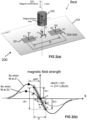
- FIG. 2(b) explains the rationale behind this formula.
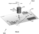
- the external position Z of the magnet can be determined by measuring the value Bu1 and Bu2 at the two sensor locations, by calculating (Bu1-Bu2)/D, and by applying the inverse relation between the slope and the Z-position (not shown).
- the actual division by the constant value D can be omitted, and can be incorporated in the inverse function "f".
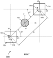
- FIG. 6 is a schematic top-view representation of a possible implementation of the system 500 of FIG. 5 according to an embodiment of the present invention.
- each sensor 601, 602 comprises two pairs of horizontal Hall elements and a disk-shaped IMC, adapted for measuring Bu1 and Bv1 both oriented substantially at 45° with respect to the imaginary line interconnecting the two sensors.
- the main purpose of this drawing is to show the relative position of the horizontal Hall plates.
- the system 800 is also highly robust against mounting or assembly tolerances.
- the magnetization axis 922 is perfectly parallel to the axis of movement 921, but the axis of movement 921 is not perfectly perpendicular to the plane 930 but is slightly tilted.
- the system 900 is also highly robust against tilting errors of the axis of movement 921.
- the magnet 1020 is movable along a movement axis or straight line 1021 which intersects with the plane 1030 in point P located substantially halfway between the first and second magnetic sensor 1001, 1002, and substantially halfway between the third and fourth magnetic sensor 1003, 1004.
- the intersection point P is also located on a virtual line forming a bisector of the angle formed by the internal U- and V-axes of each pair of sensors.
- the controller 1040 shown here as a separate component, is adapted for calculating the out-of-plane position Z of the movable magnet as a function of the values Bu1, Bv1 obtained from the first sensor 1001, and the values Bu2, Bv2 obtained from the sensor sensor 1002, and the values Bu3, Bv3 obtained from the third sensor 1003, and the values Bu4, Bv4 obtained from the fourth sensor 1004, and the distance D.
- the value D can be omitted from formula [7].
- the function of formula [8] can for example be calculated using a look-up table (and optionally also linear interpolation) and/or using a mathematical formula.
- FIG. 10 can also be considered as two pairs of a system as shown in FIG. 5 , resulting in two values for the position of the magnet 1020, for example a first value Z1 based on the values Bu1, Bv1, Bu2, Bv2 obtained from the sensors 1001 and 1002, and a second value Z2 based on the values Bu3, Bv3, Bu4, Bv4 obtained from the sensors 1003 and 1004, thus yielding two independent values which should be identical.
- the values Z1 and Z2 can be used for functional safety purposes, for example by using one pair of sensors as the principal pair for measuring the position, and the other pair as a secondary pair for detecting functional malfunction.
- control unit 1040 there is only one external control unit 1040, but as mentioned above, it is also possible to embed the control unit 1040 in one (or both) of the sensors.
- FIG. 11 shows a schematic top view of a system which can be considered to be a variant of FIG. 10 or a variant of FIG. 4 .
- the system 1100 comprises four distinct sensors 1101-1104, located on a virtual circle with diameter D, and angularly spaced apart by 90°. Each sensor is adapted for measuring a radially oriented field component.
- the values obtained from the sensors 1101 and 1102 can be combined to determine a first position Z1
- the values obtained from the sensors 1103 and 1104 can be combined to determine a second position Z2, resulting in two values for the position of the magnet 1120, which can be used for functional safety purposes.
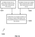
- FIG. 12 shows a flow-diagram of a method 1200 according to an embodiment of the present invention, for determining an out-of-plane position Z of an object, e.g. a permanent magnet or a ferromagnetic target, based on measurement of at least one in-plane field gradient.
- the method 1200 of FIG. 12 comprises the following steps:
- Step c) may comprise: determining the out-of-plane position Z as a function of a summation and/or subtraction of said values to obtain a value equal to or proportional to an in-plane field gradient, and using a predefined lookup-table and/or a predefined mathematical formula to convert this field-gradient to an out-of-plane position Z.
- the magnet is an axially magnetized cylindrical magnet, but the invention is not limited thereto, and other magnets can also be used, for example:
Landscapes
- Physics & Mathematics (AREA)
- General Physics & Mathematics (AREA)
- Transmission And Conversion Of Sensor Element Output (AREA)
- Measurement Of Length, Angles, Or The Like Using Electric Or Magnetic Means (AREA)
Priority Applications (1)
| Application Number | Priority Date | Filing Date | Title |
|---|---|---|---|
| EP24177159.1A EP4397939B1 (de) | 2018-08-28 | 2018-08-28 | Magnetisches positionssensorsystem |
Applications Claiming Priority (2)
| Application Number | Priority Date | Filing Date | Title |
|---|---|---|---|
| EP18191222.1A EP3617657B1 (de) | 2018-08-28 | 2018-08-28 | Sensorsystem und -verfahren für magnetische position |
| EP24177159.1A EP4397939B1 (de) | 2018-08-28 | 2018-08-28 | Magnetisches positionssensorsystem |
Related Parent Applications (1)
| Application Number | Title | Priority Date | Filing Date |
|---|---|---|---|
| EP18191222.1A Division EP3617657B1 (de) | 2018-08-28 | 2018-08-28 | Sensorsystem und -verfahren für magnetische position |
Publications (3)
| Publication Number | Publication Date |
|---|---|
| EP4397939A2 true EP4397939A2 (de) | 2024-07-10 |
| EP4397939A3 EP4397939A3 (de) | 2024-08-14 |
| EP4397939B1 EP4397939B1 (de) | 2026-04-01 |
Family
ID=63442495
Family Applications (2)
| Application Number | Title | Priority Date | Filing Date |
|---|---|---|---|
| EP18191222.1A Active EP3617657B1 (de) | 2018-08-28 | 2018-08-28 | Sensorsystem und -verfahren für magnetische position |
| EP24177159.1A Active EP4397939B1 (de) | 2018-08-28 | 2018-08-28 | Magnetisches positionssensorsystem |
Family Applications Before (1)
| Application Number | Title | Priority Date | Filing Date |
|---|---|---|---|
| EP18191222.1A Active EP3617657B1 (de) | 2018-08-28 | 2018-08-28 | Sensorsystem und -verfahren für magnetische position |
Country Status (3)
| Country | Link |
|---|---|
| US (1) | US11098996B2 (de) |
| EP (2) | EP3617657B1 (de) |
| CN (1) | CN110864612B (de) |
Families Citing this family (12)
| Publication number | Priority date | Publication date | Assignee | Title |
|---|---|---|---|---|
| EP3783316B9 (de) * | 2019-08-22 | 2022-08-10 | Melexis Technologies SA | Magnetisches sensorsystem |
| EP4325234A3 (de) * | 2020-03-23 | 2024-05-22 | Melexis Technologies SA | Vorrichtungen und verfahren zur messung eines magnetfeldgradienten |
| CN111446821B (zh) * | 2020-03-25 | 2021-01-05 | 武汉迈信电气技术有限公司 | 一种磁编码多霍尔冗余装置 |
| EP3890171A1 (de) * | 2020-04-02 | 2021-10-06 | Beckhoff Automation GmbH | Verfahren zum steuern eines planarantriebssystems und planarantriebssystem |
| EP3919922B1 (de) * | 2020-06-02 | 2024-05-29 | Melexis Technologies SA | Stromsensorsystem |
| EP3955436B1 (de) * | 2020-08-14 | 2024-01-17 | Schneider Electric Industries SAS | Linearmotorsystem und betriebsverfahren für ein solches |
| CN112014778B (zh) * | 2020-08-24 | 2023-11-07 | 歌尔微电子有限公司 | 微机电系统磁阻传感器、传感器单体及电子设备 |
| EP4399489A1 (de) * | 2021-09-09 | 2024-07-17 | Melexis Technologies SA | Magnetsensorvorrichtungen, systeme und verfahren sowie kraftsensor |
| EP4160157B1 (de) * | 2021-09-30 | 2024-11-20 | Melexis Technologies SA | Magnetisches positionssensorsystem |
| EP4610684A3 (de) * | 2022-10-19 | 2025-12-31 | Melexis Technologies SA | Vorrichtung und verfahren zur bestimmung einer orientierung eines magneten sowie joystick |
| DE102022211548B4 (de) * | 2022-10-31 | 2024-08-22 | Infineon Technologies Ag | Magnetfeldbasierte positionsbestimmungsvorrichtung und verfahren zur magnetfeldbasierten positionsbestimmung |
| CN118328826B (zh) * | 2024-06-17 | 2024-08-30 | 长江三峡集团实业发展(北京)有限公司 | 垂线坐标测量装置、系统、方法、存储介质及设备 |
Citations (2)
| Publication number | Priority date | Publication date | Assignee | Title |
|---|---|---|---|---|
| US20020021124A1 (en) | 2000-08-21 | 2002-02-21 | Christian Schott | Sensor for the detection of the direction of a magnetic field |
| WO2018122283A1 (de) | 2016-12-29 | 2018-07-05 | Robert Bosch Gmbh | Wegsensor |
Family Cites Families (6)
| Publication number | Priority date | Publication date | Assignee | Title |
|---|---|---|---|---|
| DE19914352A1 (de) * | 1999-03-30 | 2000-10-05 | Valeo Schalter & Sensoren Gmbh | Elektrischer Schalter, insbesondere Lenkstockschalter für ein Kraftfahrzeug |
| DE102010003292A1 (de) * | 2010-03-25 | 2011-09-29 | Fraunhofer-Gesellschaft zur Förderung der angewandten Forschung e.V. | Sensoranordnung und Verfahren zum Ermitteln einer Magnetisierungseinrichtung eines Gebermagneten |
| GB201014334D0 (en) * | 2010-08-27 | 2010-10-13 | Harker Benjamin | Improvements to structual separation monitoring systems, methods of installing systems and/or position sensors |
| EP2828621B1 (de) * | 2012-03-23 | 2017-09-06 | Pacific Rim Engineered Products (1987) Ltd. | Getriebekupplungsmechanismus für getriebe und zugehörige verfahren |
| US9593965B2 (en) * | 2014-12-08 | 2017-03-14 | National Chung Shan Institute Of Science And Technology | Non-contact adjustable hysteretic magnetic encoder |
| DE102015225902A1 (de) * | 2015-12-18 | 2017-06-22 | Volkswagen Aktiengesellschaft | Magnetfeldsensorvorrichtung und Verfahren zum Positionserfassen eines Wählhebels eines Kraftfahrzeugs |
-
2018
- 2018-08-28 EP EP18191222.1A patent/EP3617657B1/de active Active
- 2018-08-28 EP EP24177159.1A patent/EP4397939B1/de active Active
-
2019
- 2019-08-27 CN CN201910797907.8A patent/CN110864612B/zh active Active
- 2019-08-28 US US16/553,341 patent/US11098996B2/en active Active
Patent Citations (2)
| Publication number | Priority date | Publication date | Assignee | Title |
|---|---|---|---|---|
| US20020021124A1 (en) | 2000-08-21 | 2002-02-21 | Christian Schott | Sensor for the detection of the direction of a magnetic field |
| WO2018122283A1 (de) | 2016-12-29 | 2018-07-05 | Robert Bosch Gmbh | Wegsensor |
Also Published As
| Publication number | Publication date |
|---|---|
| US11098996B2 (en) | 2021-08-24 |
| EP4397939A3 (de) | 2024-08-14 |
| CN110864612A (zh) | 2020-03-06 |
| EP4397939B1 (de) | 2026-04-01 |
| EP3617657A1 (de) | 2020-03-04 |
| EP3617657B1 (de) | 2024-05-29 |
| CN110864612B (zh) | 2022-07-19 |
| US20200072595A1 (en) | 2020-03-05 |
Similar Documents
| Publication | Publication Date | Title |
|---|---|---|
| EP4397939B1 (de) | Magnetisches positionssensorsystem | |
| US10041780B2 (en) | Position sensor | |
| US20190242956A1 (en) | Magnetoresistive sensor systems with stray field cancellation utilizing auxiliary sensor signals | |
| US10816363B2 (en) | Angular sensor system and method of stray field cancellation | |
| EP4105768B1 (de) | Vorrichtung und verfahren zur bestimmung der orientierung eines magneten und joystick | |
| EP4206613B1 (de) | Magnetische positionssensorvorrichtung, verfahren und system mit fehlererkennung | |
| US11313922B2 (en) | Signal processing circuit and magnetic sensor system | |
| US12140647B2 (en) | Position sensor system, optical lens system and display | |
| US20230100898A1 (en) | Magnetic position sensor system | |
| CN214585084U (zh) | 一种磁传感器及基于磁传感器的无损检测装置 | |
| EP4610684A2 (de) | Vorrichtung und verfahren zur bestimmung einer orientierung eines magneten sowie joystick | |
| US11788866B2 (en) | Magnetic position sensor device, method and system, with error detection | |
| CN113608152B (zh) | 磁传感器 | |
| EP4636360A1 (de) | Sensorvorrichtung zum ermitteln einer orientierung eines magneten und sensorsystem | |
| US20250341435A1 (en) | Magnetic-based torque sensor | |
| Bratland et al. | Linear position sensing using magnetoresistive sensors |
Legal Events
| Date | Code | Title | Description |
|---|---|---|---|
| PUAI | Public reference made under article 153(3) epc to a published international application that has entered the european phase |
Free format text: ORIGINAL CODE: 0009012 |
|
| STAA | Information on the status of an ep patent application or granted ep patent |
Free format text: STATUS: THE APPLICATION HAS BEEN PUBLISHED |
|
| REG | Reference to a national code |
Ref country code: DE Ref legal event code: R079 Free format text: PREVIOUS MAIN CLASS: G01B0007000000 Ipc: G01D0005140000 Ref country code: DE Ref legal event code: R079 Ref document number: 602018090354 Country of ref document: DE Free format text: PREVIOUS MAIN CLASS: G01B0007000000 Ipc: G01D0005140000 |
|
| AC | Divisional application: reference to earlier application |
Ref document number: 3617657 Country of ref document: EP Kind code of ref document: P |
|
| AK | Designated contracting states |
Kind code of ref document: A2 Designated state(s): AL AT BE BG CH CY CZ DE DK EE ES FI FR GB GR HR HU IE IS IT LI LT LU LV MC MK MT NL NO PL PT RO RS SE SI SK SM TR |
|
| PUAL | Search report despatched |
Free format text: ORIGINAL CODE: 0009013 |
|
| AK | Designated contracting states |
Kind code of ref document: A3 Designated state(s): AL AT BE BG CH CY CZ DE DK EE ES FI FR GB GR HR HU IE IS IT LI LT LU LV MC MK MT NL NO PL PT RO RS SE SI SK SM TR |
|
| RIC1 | Information provided on ipc code assigned before grant |
Ipc: G01B 7/00 20060101ALI20240709BHEP Ipc: G01D 5/14 20060101AFI20240709BHEP |
|
| STAA | Information on the status of an ep patent application or granted ep patent |
Free format text: STATUS: REQUEST FOR EXAMINATION WAS MADE |
|
| 17P | Request for examination filed |
Effective date: 20250113 |
|
| GRAP | Despatch of communication of intention to grant a patent |
Free format text: ORIGINAL CODE: EPIDOSNIGR1 |
|
| STAA | Information on the status of an ep patent application or granted ep patent |
Free format text: STATUS: GRANT OF PATENT IS INTENDED |
|
| GRAS | Grant fee paid |
Free format text: ORIGINAL CODE: EPIDOSNIGR3 |
|
| GRAA | (expected) grant |
Free format text: ORIGINAL CODE: 0009210 |
|
| STAA | Information on the status of an ep patent application or granted ep patent |
Free format text: STATUS: THE PATENT HAS BEEN GRANTED |
|
| INTG | Intention to grant announced |
Effective date: 20260129 |
|
| AC | Divisional application: reference to earlier application |
Ref document number: 3617657 Country of ref document: EP Kind code of ref document: P |
|
| AK | Designated contracting states |
Kind code of ref document: B1 Designated state(s): AL AT BE BG CH CY CZ DE DK EE ES FI FR GB GR HR HU IE IS IT LI LT LU LV MC MK MT NL NO PL PT RO RS SE SI SK SM TR |
|
| REG | Reference to a national code |
Ref country code: CH Ref legal event code: F10 Free format text: ST27 STATUS EVENT CODE: U-0-0-F10-F00 (AS PROVIDED BY THE NATIONAL OFFICE) Effective date: 20260401 Ref country code: GB Ref legal event code: FG4D |
|
| REG | Reference to a national code |
Ref country code: DE Ref legal event code: R096 Ref document number: 602018090354 Country of ref document: DE |
|
| REG | Reference to a national code |
Ref country code: IE Ref legal event code: FG4D |