EP4397965A1 - Verfahren zum abtasten eines objekts in einer abtastvorrichtung - Google Patents
Verfahren zum abtasten eines objekts in einer abtastvorrichtung Download PDFInfo
- Publication number
- EP4397965A1 EP4397965A1 EP23214301.6A EP23214301A EP4397965A1 EP 4397965 A1 EP4397965 A1 EP 4397965A1 EP 23214301 A EP23214301 A EP 23214301A EP 4397965 A1 EP4397965 A1 EP 4397965A1
- Authority
- EP
- European Patent Office
- Prior art keywords
- rotation
- axis
- objects
- support
- jacket
- Prior art date
- Legal status (The legal status is an assumption and is not a legal conclusion. Google has not performed a legal analysis and makes no representation as to the accuracy of the status listed.)
- Withdrawn
Links
Images







Classifications
-
- G—PHYSICS
- G01—MEASURING; TESTING
- G01N—INVESTIGATING OR ANALYSING MATERIALS BY DETERMINING THEIR CHEMICAL OR PHYSICAL PROPERTIES
- G01N23/00—Investigating or analysing materials by the use of wave or particle radiation, e.g. X-rays or neutrons, not covered by groups G01N3/00 – G01N17/00, G01N21/00 or G01N22/00
- G01N23/02—Investigating or analysing materials by the use of wave or particle radiation, e.g. X-rays or neutrons, not covered by groups G01N3/00 – G01N17/00, G01N21/00 or G01N22/00 by transmitting the radiation through the material
- G01N23/04—Investigating or analysing materials by the use of wave or particle radiation, e.g. X-rays or neutrons, not covered by groups G01N3/00 – G01N17/00, G01N21/00 or G01N22/00 by transmitting the radiation through the material and forming images of the material
- G01N23/046—Investigating or analysing materials by the use of wave or particle radiation, e.g. X-rays or neutrons, not covered by groups G01N3/00 – G01N17/00, G01N21/00 or G01N22/00 by transmitting the radiation through the material and forming images of the material using tomography, e.g. computed tomography [CT]
-
- G—PHYSICS
- G01—MEASURING; TESTING
- G01N—INVESTIGATING OR ANALYSING MATERIALS BY DETERMINING THEIR CHEMICAL OR PHYSICAL PROPERTIES
- G01N23/00—Investigating or analysing materials by the use of wave or particle radiation, e.g. X-rays or neutrons, not covered by groups G01N3/00 – G01N17/00, G01N21/00 or G01N22/00
- G01N23/02—Investigating or analysing materials by the use of wave or particle radiation, e.g. X-rays or neutrons, not covered by groups G01N3/00 – G01N17/00, G01N21/00 or G01N22/00 by transmitting the radiation through the material
- G01N23/06—Investigating or analysing materials by the use of wave or particle radiation, e.g. X-rays or neutrons, not covered by groups G01N3/00 – G01N17/00, G01N21/00 or G01N22/00 by transmitting the radiation through the material and measuring the absorption
- G01N23/083—Investigating or analysing materials by the use of wave or particle radiation, e.g. X-rays or neutrons, not covered by groups G01N3/00 – G01N17/00, G01N21/00 or G01N22/00 by transmitting the radiation through the material and measuring the absorption the radiation being X-rays
-
- G—PHYSICS
- G01—MEASURING; TESTING
- G01N—INVESTIGATING OR ANALYSING MATERIALS BY DETERMINING THEIR CHEMICAL OR PHYSICAL PROPERTIES
- G01N2223/00—Investigating materials by wave or particle radiation
- G01N2223/30—Accessories, mechanical or electrical features
- G01N2223/33—Accessories, mechanical or electrical features scanning, i.e. relative motion for measurement of successive object-parts
-
- G—PHYSICS
- G01—MEASURING; TESTING
- G01N—INVESTIGATING OR ANALYSING MATERIALS BY DETERMINING THEIR CHEMICAL OR PHYSICAL PROPERTIES
- G01N2223/00—Investigating materials by wave or particle radiation
- G01N2223/60—Specific applications or type of materials
- G01N2223/63—Specific applications or type of materials turbine blades
Definitions
- the known arrangements teach that 3DCT scans of cast metal turbine blades, for example, are to be performed on one part at a time as the composition of the part may effectively attenuate the CT scanning x-ray beam.
- the known arrangements also teach that the object is to be positioned in the middle of the scanning frame, for instance with a vertical axis of rotation of a rotatable CT scanning platform extending through the object.
- the object may be inclined to create an angle between the axis of rotation and a longitudinal axis of the object. In this case, the orientation of the object may be selected to minimise the path length that the x-ray penetrates.
- the known arrangements teach that bigger and thicker objects generally produce lower quality scans as they create more beam scattering.
- a cylinder is the ideal shape to scan, because it has the same thickness whatever the angle of rotation of the table with respect to the emitter and receiver.
- Components with complex cross sections and/or cross sections that change along their length such as turbine blades and vanes face particular scanning challenges.
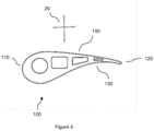
- a turbine blade may present an aerofoil cross-section with a leading edge and a trailing edge face.
- the leading-edge cross-section is thicker than the trailing edge cross-section.
- the aerofoil section of the object may have a concave blade surface on one side bounded at either end by the leading and trailing edges and a convex blade surface on the other side. Optimising the CT scan parameters for all features of the object at the same time is difficult.
- the concave surface of the blade has the potential to concentrate or converge scattered x-rays and create a high level of noise on the concave side, leading to concave side (or concave wall) effects.
- a concave wall effect produces image artifacts formed on or around the image of the object due to beam hardening and haloing.
- the scanning apparatus is a two-dimensional or three-dimensional computational tomography, CT, scanning apparatus with a table or platform which is rotatable about a vertical axis, and with oppositely disposed x-ray emitter and receiver units to either side of the table.
- the object (or part or component) may be directly supported on the platform or held within a jig (or on a support in the form of a jig). It may extend at an angle to the vertical to facilitate cross-sections at preferred angles through the object.
- the object may be offset from the axis of rotation so that its centre (for example centre of mass and/or centre of symmetry) is displaced from the axis, for example by at least half the minimum extent of the object taken in any horizontal plane.
- the object may be positioned so that the part to be scanned of the object is offset from the axis of rotation.
- the object may be positioned so that no part of the object intersects the axis of rotation.
- the object may be made of metal or composite or polymer or a mixture of materials.
- the object can be cast or moulded or machined or 3D printed (additively manufactured), for example.
- the object may be a simple shape, such as a cylinder or sphere, or a more complex object such as a component for use in a machine.
- the object may be a blade or vane or other complex manufactured part.
- the object may be a turbine blade.
- the blade may have a leading edge and a trailing edge separated by blade surfaces. In this case the blade can have any orientation with respect to the axis of rotation.
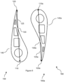
- the inventor has surprisingly found that a better image quality results when the leading edge is disposed closer to the axis of rotation than the trailing edge (that is, a line drawn from the axis to the extremity of the leading edge is shorter than the corresponding line drawn to the extremity of the trailing edge).Although, there are certain scenarios, depending on the feature of interest, where orientating the leading edge closer to the axis of rotation may not be desired.
- the convex blade surface may be disposed closer to the axis of rotation than the concave blade surface.
- this arrangement is not limited to turbine blades, any object may have a concave surface opposite a convex surface and be correspondingly positioned. This orientation too, can provide better image quality, for example because the concave surface is facing away from the axis, which has been seen to reduce the concave wall effect.
- image contrast may be improved as the concave side may be in a brighter region of the scan.
- the concave side may be pointed towards the axis of rotation and still be in the bright region to produce a good quality scan.
- the combination of a turbine blade with the leading edge closer to the axis than the trailing edge and the concave blade surface facing away from the axis has proved particularly advantageous.
- the turbine blade is not limited to a convex surface and concave surface.
- the turbine blade may have a substantially flat blade surface opposite a concave surface or two concave surfaces opposite one another or any other combination of surfaces from known arrangements.
- a plurality of objects may be disposed, offset from the axis of rotation, on the support.
- the objects may be substantially similar or identical, such as a particular size of turbine blade.
- each object may have its centre (for example centre of mass) displaced from the axis, for example by at least half the minimum extent of the object taken in any horizontal plane.
- the plurality of objects (which may be similar, substantially identical or different) may be disposed so that no part to be scanned or no part of any of the objects intersects the axis of rotation.
- an object from the plurality of objects is offset so that no part of it intersects the axis while another object from the plurality of objects may be positioned so that only the part of it to be scanned is offset, for example.
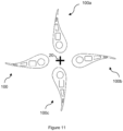
- the plurality of objects may be disposed on the support so that a notional line drawn from the emitting element to the receiving element through the axis of rotation intersects two or more of the plurality of objects for at least a third and preferably over half of the projections. That is, the projections, which are taken at equally spaced angular positions around the axis of rotation, may cover 360 degrees of rotation, and the projections over at least 120 degrees (or preferably 180 degrees) may then intersect one or more objects. With this density of object positioning comes an increase in efficiency and, contrary to the established view, the inventor has found that any decline in quality is not significant.
- the inventor has come to the surprising realisation that the scan quality may be improved as a larger amount of material allows for more power to be used for the scan without oversaturating the detector.
- scanning parameters such as the power to voxel size ratio, sometimes referred to as the power to voxel ratio, are easier to adjust to desirable values when the thickness to be scanned of the objects varies less. So, positioning of the objects in which the rays pass through at least one object for more of the projections reduces a variation in thickness to be scanned and can make parameter setting easier.
- Optimising the software scanning parameters may further improve the scanning efficiency.
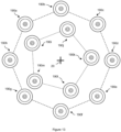
- the plurality of objects may be turbine blades each with a leading edge and a trailing edge separated by a concave blade surface opposite to a convex blade surface. They may be oriented such that the convex blade surface of each blade faces the axis of rotation, with the advantages enumerated above.
- An object or objects of the further plurality of objects may have substantially similar geometries to the plurality of objects or may be different from the plurality of objects and/or each other. Additionally or alternatively to the further plurality of objects, an attenuating object or objects such as a solid cylinder may be disposed in the inner region, for example centred on the axis.
- the objects may be positioned on some but not all of the vertices of the notional regular geometric figure (for example two of the four vertices of a square). In this case, all of the objects may be positioned to one side of a plane along which the axis of rotation extends (as seen in plan view for a vertical axis and horizontal support all the parts are to one side of a straight line drawn through the axis of rotation).
- the inventor has found that such an asymmetrical arrangement, with half of the available space left empty, provides a better quality.
- the objects may be elongate (such as the turbine blades previously described) and a shape of the configuration formed by the combined shape of the objects in the configuration may have a lower aspect ratio than a single one of the objects.
- This can give a shape of the configuration which is more similar to the "ideal" cylindrical shape for scanning in which thickness of material to be penetrated is constant for all the projections. In other words, the configuration can minimise the variation in material thickness between the emitter and receiver penetrated at the multiple relative angles of rotation.
- the aspect ratio of the configuration may be less than two thirds, or even less than half, of the aspect ratio of a single one of the objects.
- the aspect ratio of the combined shape may be computed using the aspect ratio of a rectangular bounding box around the two (or more) cross sections.
- the blades When the objects are turbine blades, the blades may be positioned in the configuration in alternate head-to-toe configuration with the leading edge of one blade positioned adjacent to the trailing edge of the adjacent blade.
- the chords of all (or both) the blades (for example, all two, three, four or more blades) in the configuration may be aligned. If the blade has convex and concave blade surfaces, and there are two blades at each vertex, the concave surface of one turbine blade at a vertex may face the concave surface of the other turbine blade. Alternatively, the convex surface of one turbine blade may be opposite the convex surface of an adjacent turbine blade.
- the arrangement may further comprise filling the volume surrounding the object within the jacket with the filling material.
- the filling material may be poured or added into the jacket after the object has been placed into the jacket.
- the jacket may completely surround the object.
- the base and side wall may be formed of a polymer film or wall and may contain the filling material.
- the jacket may have a solid volume or may contain the filling material, and in either case may surround the object so that the thickness of material to be penetrated is approximately constant for all projections.
- the polymer film or wall may have a relatively low imaging beam attenuation as compared to, for instance, the metal powder. Hence, the polymer may have a minimal effect on the image quality of the scan.
- the support may be a table which rotates about a vertical axis and the objects may be disposed on the support.
- the support may be fixed and the imaging beam emitting element and the imaging beam receiving element may rotate around a vertical axis centred on the support.
- the part of the object being scanned should remain entirely within the x-ray beam cone whilst it is rotated.
- Figure 2 is a flow chart showing steps of a method 50 for scanning of an object or a plurality of objects in a scanning apparatus.
- the object(s) is (are) disposed offset from the axis of rotation on a support in the scanning apparatus, for example manually.
- the objects may be held in a jig and so indirectly positioned on the support.
- the scanning apparatus may be, for example, substantially similar in construction to the 3DCT scanning apparatus 10.
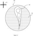
- the objects may be turbine blades 100, for example those which are depicted in Figure 3 . It will be appreciated that the objects could, however, take any form. Additionally, the objects may be disposed in a jacket 180, see Figure 14 , or plurality of jackets, before scanning.
- the objects and/or jackets may be disposed in a pattern around the axis of rotation with no part of them intersecting the axis or with no part of the object to be scanned intersecting the axis, that is no part of the object which is of interest from the scan.
- Figure 3 shows a diagonal view of an aerofoil section of a turbine blade 100. Other parts of the blade, such as a mounting section are less relevant and not shown.
- the turbine blade in this arrangement is formed from a metal material which may be cast metal, but the teaching herein can be applied to objects of any scannable material.
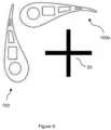
- Figure 9 shows a sectional view of two turbine blades 100 and 100a, and the axis of rotation 20.
- the first blade and the second blade are orientated favourably relative to each other and the axis of rotation.
- the first object and second object may be positioned on two adjacent vertices of the geometric shape with the trailing edge of the first blade adjacent the leading edge of the second blade.
- Figure 14 is a sectional view of the turbine blade disposed within a jacket 180.
- the jacket which in Figure 14 has a circular cross-section, but may take any suitable form, contains a filling material 170 (or may contain a solid jacket volume).
- the filing material is a powder made from the same material as the object disposed within the jacket or the jacket has a solid jacket material such that the volume surrounding the object is solid.
- the solid jacket volume may be made from the same material as object.
- the powder or solid jacket volume may, for example, be made for the cast metal.
- the objects disposed within the jacket may be made of different materials.
- the imaging beam attenuation of the filling material or solid jacket volume may be matched to one of the objects, that is the filling material or solid jacket volume may be the same as the material of one of the objects, for example.
- the composition of the filling material or solid jacket volume may be chosen so that its imaging beam attenuation is an average of the imaging beam attenuations of the objects.
- the imaging beam attenuation, and the (mass) attenuation coefficient, of the filling material or solid jacket volume may lie within the range of the imaging beam attenuations of the objects.
Landscapes
- Health & Medical Sciences (AREA)
- General Physics & Mathematics (AREA)
- Pathology (AREA)
- Life Sciences & Earth Sciences (AREA)
- Chemical & Material Sciences (AREA)
- Analytical Chemistry (AREA)
- Biochemistry (AREA)
- Physics & Mathematics (AREA)
- General Health & Medical Sciences (AREA)
- Immunology (AREA)
- Engineering & Computer Science (AREA)
- Nuclear Medicine, Radiotherapy & Molecular Imaging (AREA)
- Pulmonology (AREA)
- Radiology & Medical Imaging (AREA)
- Theoretical Computer Science (AREA)
- Toxicology (AREA)
- Analysing Materials By The Use Of Radiation (AREA)
Applications Claiming Priority (1)
| Application Number | Priority Date | Filing Date | Title |
|---|---|---|---|
| GBGB2300062.3A GB202300062D0 (en) | 2023-01-04 | 2023-01-04 | A method for scanning of an object in a scanning apparatus |
Publications (1)
| Publication Number | Publication Date |
|---|---|
| EP4397965A1 true EP4397965A1 (de) | 2024-07-10 |
Family
ID=85174494
Family Applications (1)
| Application Number | Title | Priority Date | Filing Date |
|---|---|---|---|
| EP23214301.6A Withdrawn EP4397965A1 (de) | 2023-01-04 | 2023-12-05 | Verfahren zum abtasten eines objekts in einer abtastvorrichtung |
Country Status (3)
| Country | Link |
|---|---|
| US (1) | US20240219319A1 (de) |
| EP (1) | EP4397965A1 (de) |
| GB (1) | GB202300062D0 (de) |
Families Citing this family (1)
| Publication number | Priority date | Publication date | Assignee | Title |
|---|---|---|---|---|
| GB202303164D0 (en) * | 2023-03-03 | 2023-04-19 | Rolls Royce Plc | A method for scanning of an object in a scanning apparatus |
Citations (5)
| Publication number | Priority date | Publication date | Assignee | Title |
|---|---|---|---|---|
| GB1005557A (en) * | 1964-06-08 | 1965-09-22 | Rolls Royce | Improvements in or relating to packing of test-pieces during tomography |
| CN101435784A (zh) * | 2008-10-14 | 2009-05-20 | 重庆大学 | 涡轮叶片ct检测装置及其检测方法 |
| US20160334344A1 (en) * | 2015-05-12 | 2016-11-17 | Rolls-Royce Plc | Method of scanning aerofoil blades |
| US20160334345A1 (en) * | 2015-05-12 | 2016-11-17 | Rolls-Royce Plc | Method of scanning aerofoil blades |
| WO2022087357A1 (en) * | 2020-10-24 | 2022-04-28 | Scintacor Limited | An irradiation apparatus |
-
2023
- 2023-01-04 GB GBGB2300062.3A patent/GB202300062D0/en not_active Ceased
- 2023-12-05 EP EP23214301.6A patent/EP4397965A1/de not_active Withdrawn
- 2023-12-12 US US18/536,834 patent/US20240219319A1/en active Pending
Patent Citations (5)
| Publication number | Priority date | Publication date | Assignee | Title |
|---|---|---|---|---|
| GB1005557A (en) * | 1964-06-08 | 1965-09-22 | Rolls Royce | Improvements in or relating to packing of test-pieces during tomography |
| CN101435784A (zh) * | 2008-10-14 | 2009-05-20 | 重庆大学 | 涡轮叶片ct检测装置及其检测方法 |
| US20160334344A1 (en) * | 2015-05-12 | 2016-11-17 | Rolls-Royce Plc | Method of scanning aerofoil blades |
| US20160334345A1 (en) * | 2015-05-12 | 2016-11-17 | Rolls-Royce Plc | Method of scanning aerofoil blades |
| WO2022087357A1 (en) * | 2020-10-24 | 2022-04-28 | Scintacor Limited | An irradiation apparatus |
Non-Patent Citations (2)
| Title |
|---|
| RUBERT, NSZCZYKUTOWICZ, TRANALLO, F: "Improvement in CT image resolution due to the use of focal spot deflection and increased sampling", JOURNAL OF APPLIED CLINICAL MEDICAL PHYSICS, vol. 17, no. 3, 2016, pages 452 - 466, Retrieved from the Internet <URL:https://doi.org/10.1120/jacmp.v17i3.6039> |
| VILLARRAGA-GOMEZ, HSMITH, S.T: "Effect of the number of projections on dimensional measurements with X-ray computed tomography", PRECISION ENGINEERING, vol. 66, 2020, pages 445 - 456, XP086325797, Retrieved from the Internet <URL:https://doi.org/10.1016/j.precisioneng.2020.08.006> DOI: 10.1016/j.precisioneng.2020.08.006 |
Also Published As
| Publication number | Publication date |
|---|---|
| GB202300062D0 (en) | 2023-02-15 |
| US20240219319A1 (en) | 2024-07-04 |
Similar Documents
| Publication | Publication Date | Title |
|---|---|---|
| JP4558266B2 (ja) | 複数の副画像を用いた画像再構成による円錐ビームctスキャナ | |
| US6421411B1 (en) | Methods and apparatus for helical image artifact reduction | |
| US12584870B2 (en) | Method for scanning of an object in a scanning apparatus | |
| US6229869B1 (en) | Tilted gantry image correction for a multislice computed tomography system | |
| US20100183214A1 (en) | System and Method for Highly Attenuating Material Artifact Reduction in X-Ray Computed Tomography | |
| US6366638B1 (en) | Methods and apparatus for CT scout image processing | |
| US6343108B1 (en) | Cone beam scanner using oblique surface reconstructions | |
| CN1934590A (zh) | 用于相干散射ct的射束硬化和衰减校正 | |
| US20020097830A1 (en) | Method for correcting for beam hardening in a CT image | |
| CN1251975A (zh) | 章动断层面ct图象重建 | |
| IL100313A (en) | Method and apparatus for converting cone beam x-ray projection data to planar integrals and reconstructing a three-dimensional computerized tomography (ct) image of an object | |
| KR20070051758A (ko) | X선 ct 장치 및 x선 ct 투시 장치 | |
| EP4397965A1 (de) | Verfahren zum abtasten eines objekts in einer abtastvorrichtung | |
| JP2001095794A (ja) | 斜めのスライスを使用するコンピュータ断層撮影法において画像を再構成するための装置および方法 | |
| US6839400B2 (en) | Image reconstruction method for computed tomography | |
| US12584868B2 (en) | Method for scanning of an object in a scanning apparatus | |
| EP4397966A1 (de) | Verfahren zum abtasten von objekten in einer abtastvorrichtung | |
| US8000433B2 (en) | Method of creating images in computed tomography (CT), and CT device | |
| US20090202036A1 (en) | Image reconstruction with voxel dependent interpolation | |
| JP2007130288A (ja) | X線ct撮像方法およびx線ct装置 | |
| EP2506772B1 (de) | Verfahren und system für hochauflösende taumelscheibenrekonstruktion mit vierteldetektorverschiebung | |
| US20070147580A1 (en) | Methods and apparatus for CT calibration | |
| JP5214110B2 (ja) | X線ct装置 | |
| JP7178620B2 (ja) | 検査装置及び検査方法 | |
| JP7178621B2 (ja) | 画像処理装置及び画像処理方法 |
Legal Events
| Date | Code | Title | Description |
|---|---|---|---|
| PUAI | Public reference made under article 153(3) epc to a published international application that has entered the european phase |
Free format text: ORIGINAL CODE: 0009012 |
|
| STAA | Information on the status of an ep patent application or granted ep patent |
Free format text: STATUS: THE APPLICATION HAS BEEN PUBLISHED |
|
| AK | Designated contracting states |
Kind code of ref document: A1 Designated state(s): AL AT BE BG CH CY CZ DE DK EE ES FI FR GB GR HR HU IE IS IT LI LT LU LV MC ME MK MT NL NO PL PT RO RS SE SI SK SM TR |
|
| STAA | Information on the status of an ep patent application or granted ep patent |
Free format text: STATUS: THE APPLICATION IS DEEMED TO BE WITHDRAWN |
|
| 18D | Application deemed to be withdrawn |
Effective date: 20250111 |