EP4397966A1 - Procédé de balayage d'objets dans un appareil de balayage - Google Patents
Procédé de balayage d'objets dans un appareil de balayage Download PDFInfo
- Publication number
- EP4397966A1 EP4397966A1 EP23214302.4A EP23214302A EP4397966A1 EP 4397966 A1 EP4397966 A1 EP 4397966A1 EP 23214302 A EP23214302 A EP 23214302A EP 4397966 A1 EP4397966 A1 EP 4397966A1
- Authority
- EP
- European Patent Office
- Prior art keywords
- objects
- rotation
- axis
- support
- imaging beam
- Prior art date
- Legal status (The legal status is an assumption and is not a legal conclusion. Google has not performed a legal analysis and makes no representation as to the accuracy of the status listed.)
- Granted
Links
Images




Classifications
-
- G—PHYSICS
- G01—MEASURING; TESTING
- G01N—INVESTIGATING OR ANALYSING MATERIALS BY DETERMINING THEIR CHEMICAL OR PHYSICAL PROPERTIES
- G01N23/00—Investigating or analysing materials by the use of wave or particle radiation, e.g. X-rays or neutrons, not covered by groups G01N3/00 – G01N17/00, G01N21/00 or G01N22/00
- G01N23/02—Investigating or analysing materials by the use of wave or particle radiation, e.g. X-rays or neutrons, not covered by groups G01N3/00 – G01N17/00, G01N21/00 or G01N22/00 by transmitting the radiation through the material
- G01N23/04—Investigating or analysing materials by the use of wave or particle radiation, e.g. X-rays or neutrons, not covered by groups G01N3/00 – G01N17/00, G01N21/00 or G01N22/00 by transmitting the radiation through the material and forming images of the material
- G01N23/046—Investigating or analysing materials by the use of wave or particle radiation, e.g. X-rays or neutrons, not covered by groups G01N3/00 – G01N17/00, G01N21/00 or G01N22/00 by transmitting the radiation through the material and forming images of the material using tomography, e.g. computed tomography [CT]
-
- G—PHYSICS
- G01—MEASURING; TESTING
- G01N—INVESTIGATING OR ANALYSING MATERIALS BY DETERMINING THEIR CHEMICAL OR PHYSICAL PROPERTIES
- G01N2223/00—Investigating materials by wave or particle radiation
- G01N2223/30—Accessories, mechanical or electrical features
- G01N2223/33—Accessories, mechanical or electrical features scanning, i.e. relative motion for measurement of successive object-parts
- G01N2223/3306—Accessories, mechanical or electrical features scanning, i.e. relative motion for measurement of successive object-parts object rotates
-
- G—PHYSICS
- G01—MEASURING; TESTING
- G01N—INVESTIGATING OR ANALYSING MATERIALS BY DETERMINING THEIR CHEMICAL OR PHYSICAL PROPERTIES
- G01N2223/00—Investigating materials by wave or particle radiation
- G01N2223/60—Specific applications or type of materials
- G01N2223/63—Specific applications or type of materials turbine blades
Definitions
- the concave surface of the blade has the potential to concentrate or converge scattered x-rays and create a high level of noise on the concave side, leading to concave side (or concave wall) effects.
- a concave wall effect produces image artifacts formed on or around the image of the object due to beam hardening and haloing.
- the blades may be disposed with a configuration centred on the axis of rotation with their convex surfaces facing each other and such that their convex surfaces are closer to the axis of rotation than their concave surfaces.
- this arrangement is not limited to turbine blades, any object may have a concave surface opposite a convex surface and be correspondingly positioned. This orientation too, can provide better image quality, for example because the concave surfaces are facing away from the axis, which has been seen to reduce the concave wall effect.
- the blade with the concave side facing away from the axis poor image contrast may be improved as the concave side may be in a brighter region of the scan.
- the concave side may be pointed towards the axis of rotation and still be in the bright region to produce a good quality scan.
- scanning parameters such as the power to voxel ratio, sometimes referred to as the power to voxel ratio, are easier to adjust to desirable values when the thickness to be scanned of the objects varies less. So, positioning of the objects in which the rays pass through at least one object for more of the projections reduces a variation in thickness to be scanned and can make parameter setting easier. Optimising the software scanning parameters may further improve the scanning efficiency.
- a configuration of objects may be contained within a jacket.
- the volume surrounding the objects within the jacket may be occupied by a filling material or may be a solid, that is a solid jacket volume.
- the jacket may completely surround the object or may surround the part to be scanned of the object.
- the jacket may be positioned offset to the axis of rotation.
- no part of the objects or no part of the objects to be scanned or the configuration of objects intersects the axis of rotation.
- the objects contained within the jacket may be turbine blade.
- all the aforementioned arrangements apply to the objects when they are contained within the jacket. That is, for example, a plurality of jacket configurations may be disposed on the vertices of a notional regular geometric figure or offset from the axis of rotation.
- the arrangement may further comprise filling the volume surrounding the object within the jacket with the filling material.
- the filling material may be poured or added into the jacket after the object has been placed into the jacket.
- the jacket may completely surround the object.
- the filling material may be in the form of powder, grains or fluid.
- the filling material may, for example, be either metal powder or polymer powder and thus may be poured into the jacket. This allows the filling material to completely surround the objects, filling any voids or gaps between the objects and the jacket. This may provide an approximately constant material thickness for each projection, thereby improving image quality of the scan.
- the objects may be wrapped or coated in one or more films, sleeves or walls, for example a polymer film such as cling film or a polymer membrane or a polymer bag or a polymer wall (which may be 3D printed), to provide a boundary between the objects and the filling material or the solid jacket volume.
- the one or more films, sleeves or walls may form the border region.
- the objects may be wrapped in the film, inserted into the sleeve(s) or placed between moulded walls before placing it in the jacket. This may prevent the objects contacting the filling material or solid volume and may therefore prevent contamination of the objects. Any suitable material may be used to cover the objects before they are placed in the jacket.
- the objects may be individually wrapped or covered or inserted into sleeves or may be combined.
- the film, wall or sleeve may have a low imaging beam attenuation and may therefore aid identification of the objects in the jacket by providing a contrast in the scan image at the object's surface and act as or delimit the border region mentioned above.
- the base and side wall may be formed of a polymer film or wall and may contain the filling material.
- the jacket may have a solid volume or may contain the filling material, and in either case may surround the objects so that the thickness of material to be penetrated is approximately constant for all projections.
- the polymer film or wall may have a relatively low imaging beam attenuation as compared to, for instance, the metal powder. Hence, the polymer may have a minimal effect on the image quality of the scan.
- the apparatus for scanning the objects may be a two-dimensional or three-dimensional computational tomography, CT, scanning apparatus, such as a three-dimensional, 3DCT, scanning apparatus.
- the imaging beam emitting element may emit an energy beam within the x-ray region of the electromagnetic spectrum.
- the emitted x-rays may form a polychromatic x-ray spectrum.
- the x-rays may be formed by a tungsten metal element within the imaging element.
- the emitting element may emit other energy forms such as gamma rays or ultrasound or any other energy beam suitable for scanning.
- the imaging beam emitting element and the imaging beam receiving element may be oppositely disposed to either side of the support.
- the support may be a table which rotates about a vertical axis and the objects may be disposed on the support.
- the support may be fixed and the imaging beam emitting element and the imaging beam receiving element may rotate around a vertical axis centred on the support.
- the objects and/or jackets may be disposed in a pattern around the axis of rotation with no part of them intersecting the axis or with no part to be scanned of them, that is the part of interest from the scan, intersecting the axis. This may improve scan quality.
- the scanning apparatus is operated at multiple relative angles of rotation to produce an image of the objects.
- a projection or projections may be taken at each angle around a complete 360 degrees and a complete volumetric representation of the objects may be obtained from a set of equally angularly spaced projections.
- the volumetric representation may comprise a plurality of voxels, with each voxel representing a sub-volume of the image. Subsequently the image can be viewed in cross sections, as in known arrangements.
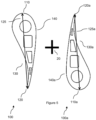
- the turbine blade comprises a leading edge 110, a trailing edge 120, and blade surfaces between these edges, such as a concave surface 130 and a convex surface 140.
- the concave surface extends in an inwardly curved shape between the leading edge and the trailing edge.
- the convex surface of the turbine blade extends in a similar manner to the concave surface, but with an outward curve and is opposite to the concave surface.
- exemplary voids are illustrated in Figure 3 . There are four voids illustrated, although it will be apparent to the skilled reader that more or fewer voids may be present.
- the aerofoil section (rather than any mounting section) is generally of primary interest when CT scanning turbine blades, and in particular the internal structure of the aerofoil section is to be investigated.
- the aerofoil section may, for example, be considered as the part of interest of the object.
- the turbine blade may be disposed on the support so that its mounting section is intersecting the axis of rotation, but the aerofoil section does not. That is, the part of the object to be scanned does not intercept the axis of rotation.
- an object in the shape of the letter 'L' may be disposed on the support. It may be that only the vertical part being scanned is offset from the axis but the bottom horizontal part may still intercept the axis of rotation.
- the turbine blade comprises an elongate aerofoil section (part) of the turbine blade having a span 115. Further, a chord 125 maybe be drawn between the extremities of the leading edge and the trailing edge.
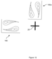
- the orientation of the first blade relative to the second blade may be understood by drawing the chords 125-125a between the extremities of the leading edge and the trailing edge.
- the orientation of the first blade relative to the second blade is such that the chord 125 of the first blade is substantially parallel to the chord 125a and spaced from it in a direction at right angles to the chords.
- the inner sides of the objects or parts of the objects will be darker than the outer sides.
- Introducing more material for the x-rays to penetrate may improve the scan quality as the power of the scanner may be adjusted to levels where previously image contrast would be reduced. The adjusted power may result in a relatively even contrast across the objects.
- other scanning parameters may be adjusted and optimised to improve the quality and efficiency of scanning the plurality of objects.
- the inventor was surprised to find that if, for example, the configuration of blades is disposed to take up only half of the available vertex positions, and therefore leave half the field clear, the scan quality is improved.
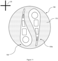
- Figure 11 is a sectional view of two turbine blades in a configuration as described above disposed within a jacket 180.
- the jacket which in Figure 11 has a circular cross-section, but may take any suitable form, contains a filling material 170 (or in another arrangement may contain a solid jacket volume).
- the filing material is a powder made from the same material as the objects disposed within the jacket or the jacket has a solid jacket material such that the volume surrounding the object is solid.
- the solid jacket volume may be made from the same material as object.
- the powder or solid jacket volume may, for example, be made from the same material as the cast metal.
- the support may rotate about the axis of rotation such that the jacket and its contents move, around the axis of rotation, within the x-ray beam cone, in the manner described above with reference to Figure 1 .
- the objects may be disposed within the jacket or the jacket may only surround the parts of the objects to be scanned. It will be understood that that either the jackets may be disposed on the support or it may be that the part of the objects not to be scanned are disposed on the support so that the jackets are in the scanning region, for example.
- Averaging out the material thickness of a plurality of objects, by disposing them in a jacket with a filling material or solid jacket volume, may reduce artifacts caused by the concave wall effect. Regions of the objects where x-rays may have been concentrated and scattered may be covered by the filling material or solid jacket volume, thus reducing scattering and beam hardening effects.
- the jacket may provide the "ideal" circular cross-section for scanning in which thickness of material to be penetrated is constant for all the projections.
- the jacket may be, for example, a cylindrical shape or spherical shape depending on the relative motion of the scanning elements in the scanning apparatus. This 'ideal' shape may further improve the image quality and contrast of the scan. Further, the 3DCT scanning parameters may be optimised, hence improving scanning efficiency.
Landscapes
- Health & Medical Sciences (AREA)
- Engineering & Computer Science (AREA)
- Nuclear Medicine, Radiotherapy & Molecular Imaging (AREA)
- Pulmonology (AREA)
- Radiology & Medical Imaging (AREA)
- Theoretical Computer Science (AREA)
- Physics & Mathematics (AREA)
- Life Sciences & Earth Sciences (AREA)
- Chemical & Material Sciences (AREA)
- Analytical Chemistry (AREA)
- Biochemistry (AREA)
- General Health & Medical Sciences (AREA)
- General Physics & Mathematics (AREA)
- Immunology (AREA)
- Pathology (AREA)
- Analysing Materials By The Use Of Radiation (AREA)
Applications Claiming Priority (1)
| Application Number | Priority Date | Filing Date | Title |
|---|---|---|---|
| GBGB2300063.1A GB202300063D0 (en) | 2023-01-04 | 2023-01-04 | A method for scanning of objects in a scanning apparatus |
Publications (2)
| Publication Number | Publication Date |
|---|---|
| EP4397966A1 true EP4397966A1 (fr) | 2024-07-10 |
| EP4397966B1 EP4397966B1 (fr) | 2025-08-13 |
Family
ID=85174497
Family Applications (1)
| Application Number | Title | Priority Date | Filing Date |
|---|---|---|---|
| EP23214302.4A Active EP4397966B1 (fr) | 2023-01-04 | 2023-12-05 | Procédé et système de balayage d'aubes de turbine dans un appareil de balayage |
Country Status (3)
| Country | Link |
|---|---|
| US (1) | US20240219320A1 (fr) |
| EP (1) | EP4397966B1 (fr) |
| GB (1) | GB202300063D0 (fr) |
Families Citing this family (1)
| Publication number | Priority date | Publication date | Assignee | Title |
|---|---|---|---|---|
| GB202303164D0 (en) * | 2023-03-03 | 2023-04-19 | Rolls Royce Plc | A method for scanning of an object in a scanning apparatus |
Citations (3)
| Publication number | Priority date | Publication date | Assignee | Title |
|---|---|---|---|---|
| GB1005557A (en) * | 1964-06-08 | 1965-09-22 | Rolls Royce | Improvements in or relating to packing of test-pieces during tomography |
| US20160334344A1 (en) * | 2015-05-12 | 2016-11-17 | Rolls-Royce Plc | Method of scanning aerofoil blades |
| US20160334345A1 (en) * | 2015-05-12 | 2016-11-17 | Rolls-Royce Plc | Method of scanning aerofoil blades |
-
2023
- 2023-01-04 GB GBGB2300063.1A patent/GB202300063D0/en not_active Ceased
- 2023-12-05 EP EP23214302.4A patent/EP4397966B1/fr active Active
- 2023-12-12 US US18/536,847 patent/US20240219320A1/en active Pending
Patent Citations (3)
| Publication number | Priority date | Publication date | Assignee | Title |
|---|---|---|---|---|
| GB1005557A (en) * | 1964-06-08 | 1965-09-22 | Rolls Royce | Improvements in or relating to packing of test-pieces during tomography |
| US20160334344A1 (en) * | 2015-05-12 | 2016-11-17 | Rolls-Royce Plc | Method of scanning aerofoil blades |
| US20160334345A1 (en) * | 2015-05-12 | 2016-11-17 | Rolls-Royce Plc | Method of scanning aerofoil blades |
Also Published As
| Publication number | Publication date |
|---|---|
| GB202300063D0 (en) | 2023-02-15 |
| US20240219320A1 (en) | 2024-07-04 |
| EP4397966B1 (fr) | 2025-08-13 |
Similar Documents
| Publication | Publication Date | Title |
|---|---|---|
| US6678346B2 (en) | Cone-beam CT scanner with image reconstruction using multiple sub-images | |
| US12584870B2 (en) | Method for scanning of an object in a scanning apparatus | |
| US8280135B2 (en) | System and method for highly attenuating material artifact reduction in x-ray computed tomography | |
| US6421411B1 (en) | Methods and apparatus for helical image artifact reduction | |
| CN101032409B (zh) | 图像显示设备和x射线ct设备 | |
| US6256365B1 (en) | Apparatus and method for reconstruction of images in a computed tomography system using oblique slices | |
| CN1934590A (zh) | 用于相干散射ct的射束硬化和衰减校正 | |
| US20020097830A1 (en) | Method for correcting for beam hardening in a CT image | |
| US6343108B1 (en) | Cone beam scanner using oblique surface reconstructions | |
| CN1251975A (zh) | 章动断层面ct图象重建 | |
| JP3787374B2 (ja) | 断層撮影画像内のアーチファクトを低減するための方法および装置 | |
| EP4397966B1 (fr) | Procédé et système de balayage d'aubes de turbine dans un appareil de balayage | |
| WO2001006931A1 (fr) | Reconstruction d'images de tomographie par ordinateur en trois dimensions | |
| US12584868B2 (en) | Method for scanning of an object in a scanning apparatus | |
| US7672424B2 (en) | Image reconstruction with voxel dependent interpolation | |
| EP4397965A1 (fr) | Procédé de balayage d'un objet dans un appareil de balayage | |
| EP3272291B1 (fr) | Dispositif et procédé de reconstruction d'image médicale | |
| US8000433B2 (en) | Method of creating images in computed tomography (CT), and CT device | |
| EP2506772B1 (fr) | Procede et systeme de reconstruction de coupe inclinee a resolution elevee au moyen d'un decalage de quart de detecteur | |
| JP5214110B2 (ja) | X線ct装置 | |
| Tang | Matched view weighting in tilted‐plane‐based reconstruction algorithms to suppress helical artifacts and optimize noise characteristics | |
| JP7178620B2 (ja) | 検査装置及び検査方法 | |
| JP2005131396A (ja) | 放射線量を低減するシステム及び方法 | |
| US6816565B1 (en) | Matched view weighting methods and apparatus using multiple tilted reconstruction planes | |
| Kwon et al. | Dental panoramic imaging by use of CBCT projection data |
Legal Events
| Date | Code | Title | Description |
|---|---|---|---|
| PUAI | Public reference made under article 153(3) epc to a published international application that has entered the european phase |
Free format text: ORIGINAL CODE: 0009012 |
|
| STAA | Information on the status of an ep patent application or granted ep patent |
Free format text: STATUS: THE APPLICATION HAS BEEN PUBLISHED |
|
| AK | Designated contracting states |
Kind code of ref document: A1 Designated state(s): AL AT BE BG CH CY CZ DE DK EE ES FI FR GB GR HR HU IE IS IT LI LT LU LV MC ME MK MT NL NO PL PT RO RS SE SI SK SM TR |
|
| STAA | Information on the status of an ep patent application or granted ep patent |
Free format text: STATUS: REQUEST FOR EXAMINATION WAS MADE |
|
| 17P | Request for examination filed |
Effective date: 20250110 |
|
| GRAP | Despatch of communication of intention to grant a patent |
Free format text: ORIGINAL CODE: EPIDOSNIGR1 |
|
| STAA | Information on the status of an ep patent application or granted ep patent |
Free format text: STATUS: GRANT OF PATENT IS INTENDED |
|
| GRAS | Grant fee paid |
Free format text: ORIGINAL CODE: EPIDOSNIGR3 |
|
| GRAA | (expected) grant |
Free format text: ORIGINAL CODE: 0009210 |
|
| STAA | Information on the status of an ep patent application or granted ep patent |
Free format text: STATUS: THE PATENT HAS BEEN GRANTED |
|
| INTG | Intention to grant announced |
Effective date: 20250624 |
|
| P01 | Opt-out of the competence of the unified patent court (upc) registered |
Free format text: CASE NUMBER: APP_31950/2025 Effective date: 20250702 |
|
| AK | Designated contracting states |
Kind code of ref document: B1 Designated state(s): AL AT BE BG CH CY CZ DE DK EE ES FI FR GB GR HR HU IE IS IT LI LT LU LV MC ME MK MT NL NO PL PT RO RS SE SI SK SM TR |
|
| REG | Reference to a national code |
Ref country code: GB Ref legal event code: FG4D |
|
| REG | Reference to a national code |
Ref country code: CH Ref legal event code: EP |
|
| REG | Reference to a national code |
Ref country code: DE Ref legal event code: R096 Ref document number: 602023005698 Country of ref document: DE |
|
| REG | Reference to a national code |
Ref country code: IE Ref legal event code: FG4D |
|
| REG | Reference to a national code |
Ref country code: NL Ref legal event code: MP Effective date: 20250813 |
|
| PG25 | Lapsed in a contracting state [announced via postgrant information from national office to epo] |
Ref country code: IS Free format text: LAPSE BECAUSE OF FAILURE TO SUBMIT A TRANSLATION OF THE DESCRIPTION OR TO PAY THE FEE WITHIN THE PRESCRIBED TIME-LIMIT Effective date: 20251213 |
|
| PG25 | Lapsed in a contracting state [announced via postgrant information from national office to epo] |
Ref country code: NO Free format text: LAPSE BECAUSE OF FAILURE TO SUBMIT A TRANSLATION OF THE DESCRIPTION OR TO PAY THE FEE WITHIN THE PRESCRIBED TIME-LIMIT Effective date: 20251113 |
|
| REG | Reference to a national code |
Ref country code: LT Ref legal event code: MG9D |
|
| PG25 | Lapsed in a contracting state [announced via postgrant information from national office to epo] |
Ref country code: PT Free format text: LAPSE BECAUSE OF FAILURE TO SUBMIT A TRANSLATION OF THE DESCRIPTION OR TO PAY THE FEE WITHIN THE PRESCRIBED TIME-LIMIT Effective date: 20251215 |
|
| PG25 | Lapsed in a contracting state [announced via postgrant information from national office to epo] |
Ref country code: FI Free format text: LAPSE BECAUSE OF FAILURE TO SUBMIT A TRANSLATION OF THE DESCRIPTION OR TO PAY THE FEE WITHIN THE PRESCRIBED TIME-LIMIT Effective date: 20250813 |
|
| PG25 | Lapsed in a contracting state [announced via postgrant information from national office to epo] |
Ref country code: NL Free format text: LAPSE BECAUSE OF FAILURE TO SUBMIT A TRANSLATION OF THE DESCRIPTION OR TO PAY THE FEE WITHIN THE PRESCRIBED TIME-LIMIT Effective date: 20250813 Ref country code: HR Free format text: LAPSE BECAUSE OF FAILURE TO SUBMIT A TRANSLATION OF THE DESCRIPTION OR TO PAY THE FEE WITHIN THE PRESCRIBED TIME-LIMIT Effective date: 20250813 |
|
| PGFP | Annual fee paid to national office [announced via postgrant information from national office to epo] |
Ref country code: FR Payment date: 20251230 Year of fee payment: 3 |
|
| PG25 | Lapsed in a contracting state [announced via postgrant information from national office to epo] |
Ref country code: GR Free format text: LAPSE BECAUSE OF FAILURE TO SUBMIT A TRANSLATION OF THE DESCRIPTION OR TO PAY THE FEE WITHIN THE PRESCRIBED TIME-LIMIT Effective date: 20251114 |
|
| PG25 | Lapsed in a contracting state [announced via postgrant information from national office to epo] |
Ref country code: SE Free format text: LAPSE BECAUSE OF FAILURE TO SUBMIT A TRANSLATION OF THE DESCRIPTION OR TO PAY THE FEE WITHIN THE PRESCRIBED TIME-LIMIT Effective date: 20250813 |
|
| PG25 | Lapsed in a contracting state [announced via postgrant information from national office to epo] |
Ref country code: LV Free format text: LAPSE BECAUSE OF FAILURE TO SUBMIT A TRANSLATION OF THE DESCRIPTION OR TO PAY THE FEE WITHIN THE PRESCRIBED TIME-LIMIT Effective date: 20250813 |
|
| PG25 | Lapsed in a contracting state [announced via postgrant information from national office to epo] |
Ref country code: PL Free format text: LAPSE BECAUSE OF FAILURE TO SUBMIT A TRANSLATION OF THE DESCRIPTION OR TO PAY THE FEE WITHIN THE PRESCRIBED TIME-LIMIT Effective date: 20250813 Ref country code: BG Free format text: LAPSE BECAUSE OF FAILURE TO SUBMIT A TRANSLATION OF THE DESCRIPTION OR TO PAY THE FEE WITHIN THE PRESCRIBED TIME-LIMIT Effective date: 20250813 |
|
| PG25 | Lapsed in a contracting state [announced via postgrant information from national office to epo] |
Ref country code: RS Free format text: LAPSE BECAUSE OF FAILURE TO SUBMIT A TRANSLATION OF THE DESCRIPTION OR TO PAY THE FEE WITHIN THE PRESCRIBED TIME-LIMIT Effective date: 20251113 |
|
| PG25 | Lapsed in a contracting state [announced via postgrant information from national office to epo] |
Ref country code: ES Free format text: LAPSE BECAUSE OF FAILURE TO SUBMIT A TRANSLATION OF THE DESCRIPTION OR TO PAY THE FEE WITHIN THE PRESCRIBED TIME-LIMIT Effective date: 20250813 |
|
| REG | Reference to a national code |
Ref country code: AT Ref legal event code: MK05 Ref document number: 1825150 Country of ref document: AT Kind code of ref document: T Effective date: 20250813 |
|
| PG25 | Lapsed in a contracting state [announced via postgrant information from national office to epo] |
Ref country code: RO Free format text: LAPSE BECAUSE OF FAILURE TO SUBMIT A TRANSLATION OF THE DESCRIPTION OR TO PAY THE FEE WITHIN THE PRESCRIBED TIME-LIMIT Effective date: 20250813 |
|
| PG25 | Lapsed in a contracting state [announced via postgrant information from national office to epo] |
Ref country code: SM Free format text: LAPSE BECAUSE OF FAILURE TO SUBMIT A TRANSLATION OF THE DESCRIPTION OR TO PAY THE FEE WITHIN THE PRESCRIBED TIME-LIMIT Effective date: 20250813 |
|
| PG25 | Lapsed in a contracting state [announced via postgrant information from national office to epo] |
Ref country code: DK Free format text: LAPSE BECAUSE OF FAILURE TO SUBMIT A TRANSLATION OF THE DESCRIPTION OR TO PAY THE FEE WITHIN THE PRESCRIBED TIME-LIMIT Effective date: 20250813 |
|
| PGFP | Annual fee paid to national office [announced via postgrant information from national office to epo] |
Ref country code: DE Payment date: 20251229 Year of fee payment: 3 |
|
| PG25 | Lapsed in a contracting state [announced via postgrant information from national office to epo] |
Ref country code: AT Free format text: LAPSE BECAUSE OF FAILURE TO SUBMIT A TRANSLATION OF THE DESCRIPTION OR TO PAY THE FEE WITHIN THE PRESCRIBED TIME-LIMIT Effective date: 20250813 |
|
| PG25 | Lapsed in a contracting state [announced via postgrant information from national office to epo] |
Ref country code: IT Free format text: LAPSE BECAUSE OF FAILURE TO SUBMIT A TRANSLATION OF THE DESCRIPTION OR TO PAY THE FEE WITHIN THE PRESCRIBED TIME-LIMIT Effective date: 20250813 |
|
| PG25 | Lapsed in a contracting state [announced via postgrant information from national office to epo] |
Ref country code: CZ Free format text: LAPSE BECAUSE OF FAILURE TO SUBMIT A TRANSLATION OF THE DESCRIPTION OR TO PAY THE FEE WITHIN THE PRESCRIBED TIME-LIMIT Effective date: 20250813 |
|
| PG25 | Lapsed in a contracting state [announced via postgrant information from national office to epo] |
Ref country code: EE Free format text: LAPSE BECAUSE OF FAILURE TO SUBMIT A TRANSLATION OF THE DESCRIPTION OR TO PAY THE FEE WITHIN THE PRESCRIBED TIME-LIMIT Effective date: 20250813 Ref country code: SK Free format text: LAPSE BECAUSE OF FAILURE TO SUBMIT A TRANSLATION OF THE DESCRIPTION OR TO PAY THE FEE WITHIN THE PRESCRIBED TIME-LIMIT Effective date: 20250813 |