EP4397987A1 - Positionnement avec des satellites virtuels - Google Patents
Positionnement avec des satellites virtuels Download PDFInfo
- Publication number
- EP4397987A1 EP4397987A1 EP23150801.1A EP23150801A EP4397987A1 EP 4397987 A1 EP4397987 A1 EP 4397987A1 EP 23150801 A EP23150801 A EP 23150801A EP 4397987 A1 EP4397987 A1 EP 4397987A1
- Authority
- EP
- European Patent Office
- Prior art keywords
- wireless communication
- communication device
- receiver
- wireless
- infrastructure network
- Prior art date
- Legal status (The legal status is an assumption and is not a legal conclusion. Google has not performed a legal analysis and makes no representation as to the accuracy of the status listed.)
- Pending
Links
- 238000004891 communication Methods 0.000 claims abstract description 347
- 238000000034 method Methods 0.000 claims abstract description 59
- 238000001228 spectrum Methods 0.000 claims abstract description 54
- 238000005259 measurement Methods 0.000 claims description 91
- 230000007480 spreading Effects 0.000 claims description 78
- 238000003892 spreading Methods 0.000 claims description 78
- 238000004364 calculation method Methods 0.000 claims description 22
- 238000004590 computer program Methods 0.000 claims description 8
- 230000001413 cellular effect Effects 0.000 description 32
- 230000006870 function Effects 0.000 description 19
- 238000012545 processing Methods 0.000 description 12
- 230000008569 process Effects 0.000 description 6
- 230000005540 biological transmission Effects 0.000 description 4
- 230000010267 cellular communication Effects 0.000 description 4
- 238000010586 diagram Methods 0.000 description 4
- 238000005516 engineering process Methods 0.000 description 4
- 239000004065 semiconductor Substances 0.000 description 4
- 238000013459 approach Methods 0.000 description 3
- 230000008859 change Effects 0.000 description 3
- QVFWZNCVPCJQOP-UHFFFAOYSA-N chloralodol Chemical compound CC(O)(C)CC(C)OC(O)C(Cl)(Cl)Cl QVFWZNCVPCJQOP-UHFFFAOYSA-N 0.000 description 3
- 238000013461 design Methods 0.000 description 3
- 230000001360 synchronised effect Effects 0.000 description 3
- 230000036541 health Effects 0.000 description 2
- 238000009434 installation Methods 0.000 description 2
- 230000003993 interaction Effects 0.000 description 2
- 239000000203 mixture Substances 0.000 description 2
- 230000003287 optical effect Effects 0.000 description 2
- XUIMIQQOPSSXEZ-UHFFFAOYSA-N Silicon Chemical compound [Si] XUIMIQQOPSSXEZ-UHFFFAOYSA-N 0.000 description 1
- 230000003321 amplification Effects 0.000 description 1
- 230000003416 augmentation Effects 0.000 description 1
- 230000008901 benefit Effects 0.000 description 1
- 230000002457 bidirectional effect Effects 0.000 description 1
- 230000001364 causal effect Effects 0.000 description 1
- 230000008602 contraction Effects 0.000 description 1
- 238000012937 correction Methods 0.000 description 1
- 238000005314 correlation function Methods 0.000 description 1
- 238000013500 data storage Methods 0.000 description 1
- 230000001419 dependent effect Effects 0.000 description 1
- 230000008030 elimination Effects 0.000 description 1
- 238000003379 elimination reaction Methods 0.000 description 1
- 238000001914 filtration Methods 0.000 description 1
- 238000004519 manufacturing process Methods 0.000 description 1
- 238000003199 nucleic acid amplification method Methods 0.000 description 1
- 229910052710 silicon Inorganic materials 0.000 description 1
- 239000010703 silicon Substances 0.000 description 1
- 230000002269 spontaneous effect Effects 0.000 description 1
- 230000003068 static effect Effects 0.000 description 1
- 238000003860 storage Methods 0.000 description 1
- 239000000758 substrate Substances 0.000 description 1
Images


Classifications
-
- G—PHYSICS
- G01—MEASURING; TESTING
- G01S—RADIO DIRECTION-FINDING; RADIO NAVIGATION; DETERMINING DISTANCE OR VELOCITY BY USE OF RADIO WAVES; LOCATING OR PRESENCE-DETECTING BY USE OF THE REFLECTION OR RERADIATION OF RADIO WAVES; ANALOGOUS ARRANGEMENTS USING OTHER WAVES
- G01S19/00—Satellite radio beacon positioning systems; Determining position, velocity or attitude using signals transmitted by such systems
- G01S19/01—Satellite radio beacon positioning systems transmitting time-stamped messages, e.g. GPS [Global Positioning System], GLONASS [Global Orbiting Navigation Satellite System] or GALILEO
- G01S19/13—Receivers
- G01S19/24—Acquisition or tracking or demodulation of signals transmitted by the system
- G01S19/29—Acquisition or tracking or demodulation of signals transmitted by the system carrier including Doppler, related
-
- H—ELECTRICITY
- H04—ELECTRIC COMMUNICATION TECHNIQUE
- H04W—WIRELESS COMMUNICATION NETWORKS
- H04W64/00—Locating users or terminals or network equipment for network management purposes, e.g. mobility management
-
- G—PHYSICS
- G01—MEASURING; TESTING
- G01S—RADIO DIRECTION-FINDING; RADIO NAVIGATION; DETERMINING DISTANCE OR VELOCITY BY USE OF RADIO WAVES; LOCATING OR PRESENCE-DETECTING BY USE OF THE REFLECTION OR RERADIATION OF RADIO WAVES; ANALOGOUS ARRANGEMENTS USING OTHER WAVES
- G01S1/00—Beacons or beacon systems transmitting signals having a characteristic or characteristics capable of being detected by non-directional receivers and defining directions, positions, or position lines fixed relatively to the beacon transmitters; Receivers co-operating therewith
- G01S1/02—Beacons or beacon systems transmitting signals having a characteristic or characteristics capable of being detected by non-directional receivers and defining directions, positions, or position lines fixed relatively to the beacon transmitters; Receivers co-operating therewith using radio waves
- G01S1/04—Details
- G01S1/042—Transmitters
-
- G—PHYSICS
- G01—MEASURING; TESTING
- G01S—RADIO DIRECTION-FINDING; RADIO NAVIGATION; DETERMINING DISTANCE OR VELOCITY BY USE OF RADIO WAVES; LOCATING OR PRESENCE-DETECTING BY USE OF THE REFLECTION OR RERADIATION OF RADIO WAVES; ANALOGOUS ARRANGEMENTS USING OTHER WAVES
- G01S1/00—Beacons or beacon systems transmitting signals having a characteristic or characteristics capable of being detected by non-directional receivers and defining directions, positions, or position lines fixed relatively to the beacon transmitters; Receivers co-operating therewith
- G01S1/02—Beacons or beacon systems transmitting signals having a characteristic or characteristics capable of being detected by non-directional receivers and defining directions, positions, or position lines fixed relatively to the beacon transmitters; Receivers co-operating therewith using radio waves
- G01S1/04—Details
- G01S1/045—Receivers
-
- G—PHYSICS
- G01—MEASURING; TESTING
- G01S—RADIO DIRECTION-FINDING; RADIO NAVIGATION; DETERMINING DISTANCE OR VELOCITY BY USE OF RADIO WAVES; LOCATING OR PRESENCE-DETECTING BY USE OF THE REFLECTION OR RERADIATION OF RADIO WAVES; ANALOGOUS ARRANGEMENTS USING OTHER WAVES
- G01S19/00—Satellite radio beacon positioning systems; Determining position, velocity or attitude using signals transmitted by such systems
- G01S19/01—Satellite radio beacon positioning systems transmitting time-stamped messages, e.g. GPS [Global Positioning System], GLONASS [Global Orbiting Navigation Satellite System] or GALILEO
- G01S19/03—Cooperating elements; Interaction or communication between different cooperating elements or between cooperating elements and receivers
- G01S19/10—Cooperating elements; Interaction or communication between different cooperating elements or between cooperating elements and receivers providing dedicated supplementary positioning signals
-
- G—PHYSICS
- G01—MEASURING; TESTING
- G01S—RADIO DIRECTION-FINDING; RADIO NAVIGATION; DETERMINING DISTANCE OR VELOCITY BY USE OF RADIO WAVES; LOCATING OR PRESENCE-DETECTING BY USE OF THE REFLECTION OR RERADIATION OF RADIO WAVES; ANALOGOUS ARRANGEMENTS USING OTHER WAVES
- G01S19/00—Satellite radio beacon positioning systems; Determining position, velocity or attitude using signals transmitted by such systems
- G01S19/01—Satellite radio beacon positioning systems transmitting time-stamped messages, e.g. GPS [Global Positioning System], GLONASS [Global Orbiting Navigation Satellite System] or GALILEO
- G01S19/03—Cooperating elements; Interaction or communication between different cooperating elements or between cooperating elements and receivers
- G01S19/10—Cooperating elements; Interaction or communication between different cooperating elements or between cooperating elements and receivers providing dedicated supplementary positioning signals
- G01S19/11—Cooperating elements; Interaction or communication between different cooperating elements or between cooperating elements and receivers providing dedicated supplementary positioning signals wherein the cooperating elements are pseudolites or satellite radio beacon positioning system signal repeaters
- G01S19/115—Airborne or satellite based pseudolites or repeaters
-
- G—PHYSICS
- G01—MEASURING; TESTING
- G01S—RADIO DIRECTION-FINDING; RADIO NAVIGATION; DETERMINING DISTANCE OR VELOCITY BY USE OF RADIO WAVES; LOCATING OR PRESENCE-DETECTING BY USE OF THE REFLECTION OR RERADIATION OF RADIO WAVES; ANALOGOUS ARRANGEMENTS USING OTHER WAVES
- G01S19/00—Satellite radio beacon positioning systems; Determining position, velocity or attitude using signals transmitted by such systems
- G01S19/01—Satellite radio beacon positioning systems transmitting time-stamped messages, e.g. GPS [Global Positioning System], GLONASS [Global Orbiting Navigation Satellite System] or GALILEO
- G01S19/13—Receivers
- G01S19/35—Constructional details or hardware or software details of the signal processing chain
- G01S19/37—Hardware or software details of the signal processing chain
-
- G—PHYSICS
- G01—MEASURING; TESTING
- G01S—RADIO DIRECTION-FINDING; RADIO NAVIGATION; DETERMINING DISTANCE OR VELOCITY BY USE OF RADIO WAVES; LOCATING OR PRESENCE-DETECTING BY USE OF THE REFLECTION OR RERADIATION OF RADIO WAVES; ANALOGOUS ARRANGEMENTS USING OTHER WAVES
- G01S19/00—Satellite radio beacon positioning systems; Determining position, velocity or attitude using signals transmitted by such systems
- G01S19/38—Determining a navigation solution using signals transmitted by a satellite radio beacon positioning system
- G01S19/39—Determining a navigation solution using signals transmitted by a satellite radio beacon positioning system the satellite radio beacon positioning system transmitting time-stamped messages, e.g. GPS [Global Positioning System], GLONASS [Global Orbiting Navigation Satellite System] or GALILEO
- G01S19/42—Determining position
- G01S19/43—Determining position using carrier phase measurements, e.g. kinematic positioning; using long or short baseline interferometry
-
- G—PHYSICS
- G01—MEASURING; TESTING
- G01S—RADIO DIRECTION-FINDING; RADIO NAVIGATION; DETERMINING DISTANCE OR VELOCITY BY USE OF RADIO WAVES; LOCATING OR PRESENCE-DETECTING BY USE OF THE REFLECTION OR RERADIATION OF RADIO WAVES; ANALOGOUS ARRANGEMENTS USING OTHER WAVES
- G01S19/00—Satellite radio beacon positioning systems; Determining position, velocity or attitude using signals transmitted by such systems
- G01S19/38—Determining a navigation solution using signals transmitted by a satellite radio beacon positioning system
- G01S19/39—Determining a navigation solution using signals transmitted by a satellite radio beacon positioning system the satellite radio beacon positioning system transmitting time-stamped messages, e.g. GPS [Global Positioning System], GLONASS [Global Orbiting Navigation Satellite System] or GALILEO
- G01S19/42—Determining position
- G01S19/45—Determining position by combining measurements of signals from the satellite radio beacon positioning system with a supplementary measurement
- G01S19/46—Determining position by combining measurements of signals from the satellite radio beacon positioning system with a supplementary measurement the supplementary measurement being of a radio-wave signal type
-
- G—PHYSICS
- G01—MEASURING; TESTING
- G01S—RADIO DIRECTION-FINDING; RADIO NAVIGATION; DETERMINING DISTANCE OR VELOCITY BY USE OF RADIO WAVES; LOCATING OR PRESENCE-DETECTING BY USE OF THE REFLECTION OR RERADIATION OF RADIO WAVES; ANALOGOUS ARRANGEMENTS USING OTHER WAVES
- G01S5/00—Position-fixing by co-ordinating two or more direction or position line determinations; Position-fixing by co-ordinating two or more distance determinations
- G01S5/02—Position-fixing by co-ordinating two or more direction or position line determinations; Position-fixing by co-ordinating two or more distance determinations using radio waves
- G01S5/0205—Details
- G01S5/0221—Receivers
-
- G—PHYSICS
- G01—MEASURING; TESTING
- G01S—RADIO DIRECTION-FINDING; RADIO NAVIGATION; DETERMINING DISTANCE OR VELOCITY BY USE OF RADIO WAVES; LOCATING OR PRESENCE-DETECTING BY USE OF THE REFLECTION OR RERADIATION OF RADIO WAVES; ANALOGOUS ARRANGEMENTS USING OTHER WAVES
- G01S5/00—Position-fixing by co-ordinating two or more direction or position line determinations; Position-fixing by co-ordinating two or more distance determinations
- G01S5/02—Position-fixing by co-ordinating two or more direction or position line determinations; Position-fixing by co-ordinating two or more distance determinations using radio waves
- G01S5/0205—Details
- G01S5/0242—Determining the position of transmitters to be subsequently used in positioning
-
- H—ELECTRICITY
- H04—ELECTRIC COMMUNICATION TECHNIQUE
- H04B—TRANSMISSION
- H04B1/00—Details of transmission systems, not covered by a single one of groups H04B3/00 - H04B13/00; Details of transmission systems not characterised by the medium used for transmission
- H04B1/69—Spread spectrum techniques
- H04B1/707—Spread spectrum techniques using direct sequence modulation
-
- G—PHYSICS
- G01—MEASURING; TESTING
- G01S—RADIO DIRECTION-FINDING; RADIO NAVIGATION; DETERMINING DISTANCE OR VELOCITY BY USE OF RADIO WAVES; LOCATING OR PRESENCE-DETECTING BY USE OF THE REFLECTION OR RERADIATION OF RADIO WAVES; ANALOGOUS ARRANGEMENTS USING OTHER WAVES
- G01S1/00—Beacons or beacon systems transmitting signals having a characteristic or characteristics capable of being detected by non-directional receivers and defining directions, positions, or position lines fixed relatively to the beacon transmitters; Receivers co-operating therewith
- G01S1/02—Beacons or beacon systems transmitting signals having a characteristic or characteristics capable of being detected by non-directional receivers and defining directions, positions, or position lines fixed relatively to the beacon transmitters; Receivers co-operating therewith using radio waves
- G01S1/68—Marker, boundary, call-sign, or like beacons transmitting signals not carrying directional information
-
- G—PHYSICS
- G01—MEASURING; TESTING
- G01S—RADIO DIRECTION-FINDING; RADIO NAVIGATION; DETERMINING DISTANCE OR VELOCITY BY USE OF RADIO WAVES; LOCATING OR PRESENCE-DETECTING BY USE OF THE REFLECTION OR RERADIATION OF RADIO WAVES; ANALOGOUS ARRANGEMENTS USING OTHER WAVES
- G01S13/00—Systems using the reflection or reradiation of radio waves, e.g. radar systems; Analogous systems using reflection or reradiation of waves whose nature or wavelength is irrelevant or unspecified
- G01S13/74—Systems using reradiation of radio waves, e.g. secondary radar systems; Analogous systems
- G01S13/76—Systems using reradiation of radio waves, e.g. secondary radar systems; Analogous systems wherein pulse-type signals are transmitted
-
- G—PHYSICS
- G01—MEASURING; TESTING
- G01S—RADIO DIRECTION-FINDING; RADIO NAVIGATION; DETERMINING DISTANCE OR VELOCITY BY USE OF RADIO WAVES; LOCATING OR PRESENCE-DETECTING BY USE OF THE REFLECTION OR RERADIATION OF RADIO WAVES; ANALOGOUS ARRANGEMENTS USING OTHER WAVES
- G01S2205/00—Position-fixing by co-ordinating two or more direction or position line determinations; Position-fixing by co-ordinating two or more distance determinations
- G01S2205/01—Position-fixing by co-ordinating two or more direction or position line determinations; Position-fixing by co-ordinating two or more distance determinations specially adapted for specific applications
-
- G—PHYSICS
- G01—MEASURING; TESTING
- G01S—RADIO DIRECTION-FINDING; RADIO NAVIGATION; DETERMINING DISTANCE OR VELOCITY BY USE OF RADIO WAVES; LOCATING OR PRESENCE-DETECTING BY USE OF THE REFLECTION OR RERADIATION OF RADIO WAVES; ANALOGOUS ARRANGEMENTS USING OTHER WAVES
- G01S2205/00—Position-fixing by co-ordinating two or more direction or position line determinations; Position-fixing by co-ordinating two or more distance determinations
- G01S2205/01—Position-fixing by co-ordinating two or more direction or position line determinations; Position-fixing by co-ordinating two or more distance determinations specially adapted for specific applications
- G01S2205/02—Indoor
-
- G—PHYSICS
- G01—MEASURING; TESTING
- G01S—RADIO DIRECTION-FINDING; RADIO NAVIGATION; DETERMINING DISTANCE OR VELOCITY BY USE OF RADIO WAVES; LOCATING OR PRESENCE-DETECTING BY USE OF THE REFLECTION OR RERADIATION OF RADIO WAVES; ANALOGOUS ARRANGEMENTS USING OTHER WAVES
- G01S5/00—Position-fixing by co-ordinating two or more direction or position line determinations; Position-fixing by co-ordinating two or more distance determinations
- G01S5/0009—Transmission of position information to remote stations
- G01S5/0018—Transmission from mobile station to base station
- G01S5/0036—Transmission from mobile station to base station of measured values, i.e. measurement on mobile and position calculation on base station
-
- G—PHYSICS
- G01—MEASURING; TESTING
- G01S—RADIO DIRECTION-FINDING; RADIO NAVIGATION; DETERMINING DISTANCE OR VELOCITY BY USE OF RADIO WAVES; LOCATING OR PRESENCE-DETECTING BY USE OF THE REFLECTION OR RERADIATION OF RADIO WAVES; ANALOGOUS ARRANGEMENTS USING OTHER WAVES
- G01S5/00—Position-fixing by co-ordinating two or more direction or position line determinations; Position-fixing by co-ordinating two or more distance determinations
- G01S5/02—Position-fixing by co-ordinating two or more direction or position line determinations; Position-fixing by co-ordinating two or more distance determinations using radio waves
- G01S5/14—Determining absolute distances from a plurality of spaced points of known location
-
- G—PHYSICS
- G01—MEASURING; TESTING
- G01S—RADIO DIRECTION-FINDING; RADIO NAVIGATION; DETERMINING DISTANCE OR VELOCITY BY USE OF RADIO WAVES; LOCATING OR PRESENCE-DETECTING BY USE OF THE REFLECTION OR RERADIATION OF RADIO WAVES; ANALOGOUS ARRANGEMENTS USING OTHER WAVES
- G01S5/00—Position-fixing by co-ordinating two or more direction or position line determinations; Position-fixing by co-ordinating two or more distance determinations
- G01S5/02—Position-fixing by co-ordinating two or more direction or position line determinations; Position-fixing by co-ordinating two or more distance determinations using radio waves
- G01S5/14—Determining absolute distances from a plurality of spaced points of known location
- G01S5/145—Using a supplementary range measurement, e.g. based on pseudo-range measurements
Definitions
- the present invention relates to terrestrial positioning systems. It may have particular relevance to applications concerning positioning for internet of things (IoT) devices.
- IoT internet of things
- GNSS Global Positioning System
- Galileo Galileo
- GLONASS BeiDou Navigation Satellite System
- BDS BeiDou Navigation Satellite System
- Each GNSS comprises a constellation of satellites, also known in the art as “space vehicles” (SVs), which orbit the earth.
- SVs space vehicles
- PRN Pseudorandom noise
- each SV transmits a number of satellite signals for instance including a Pseudorandom noise (PRN) code at a certain frequency, like for instance 1023 Mbps for GPS, and a navigation data message at a lower frequency, like for instance 50 bps for GPS.
- PRN Pseudorandom noise
- the GNSS receiver can generate a number of code phase, carrier phase and/or Doppler measurements using the signals, to derive information about the distance between the receiver and respective satellites (and/or the rate of change of these distances).
- the receiver's position can then be calculated.
- this conventional model imposes burdens on the GNSS receiver, in terms of the computational resources required for - and energy consumed by - performing the calculations on board, and receiving the assistance data on the cellular downlink.
- the GNSS receiver transmits its phase and Doppler measurements to the remote device. This may involve a relatively small data payload.
- the remote device processes the GNSS measurements to calculate the position fix.
- the remote device may obtain aiding/assistance information, to assist in the calculation.
- the latter approach is well suited to energy-constrained internet of things (IoT) applications. It can reduce the amount of data that needs to be transmitted to and from the GNSS receiver (for example, over the cellular communications network or LoRa or Sigfox or a non-terrestrial communications network). No aiding/assistance information needs to be transmitted to the GNSS receiver, since the GNSS receiver is not responsible for the calculation of the position fix. Indeed, if the GNSS receiver is configured to provide position updates according to a fixed schedule (for example, hourly or daily), little or no downstream communication may be necessary from the cellular network (or LoRa or Sigfox or a non-terrestrial communications network) to the GNSS receiver.
- a fixed schedule for example, hourly or daily
- the quantity of data necessary to transmit the measurements on the uplink, to the remote device may be relatively modest.
- the computationally intensive burden of calculating the position fix is no longer borne by the GNSS receiver, meaning that simpler, cheaper, and more power-efficient GNSS receiver devices can be designed.
- the devices can only supply usable GNSS measurements when they are able to receive satellite signals. This means that when devices are located deep indoors, it may be impossible to calculate their positions.
- a pseudolite is a terrestrial beacon that broadcasts a positioning signal in a manner similar to a GNSS satellite.
- a collection of pseudolites can be used to provide a positioning service in the local area in which they are deployed.
- the name “pseudolite” is a contraction of "pseudo-satellite", as the devices are intended to provide ground-based augmentation or replacement of GNSS satellite signals.
- Some pseudolites use GNSS frequency bands for the positioning signals that they transmit.
- Examples of this type of wireless communication device may be described as "tag” devices. They are operable at least to receive signals useful for positioning.
- the at least one signal may be referred to as a "virtual satellite" signal.
- Each tag may search for GNSS signals and, if they are not available or they are not enough, for virtual satellite signals.
- the processor may be configured to, in the second time interval, control the receiver to receive direct sequence spread spectrum reference signals in the predefined ISM band, from at least three, four, or five respective second devices (each direct sequence spread spectrum reference signal comprising a carrier signal modulated by a spreading code, wherein each spreading code is defined by a respective pseudo-random noise sequence).
- each direct sequence spread spectrum reference signal comprising a carrier signal modulated by a spreading code, wherein each spreading code is defined by a respective pseudo-random noise sequence.
- each direct sequence spread spectrum reference signal comprising a carrier signal modulated by a spreading code, wherein each spreading code is defined by a respective pseudo-random noise sequence.
- a “wireless infrastructure network” is defined as a wireless network that is organised in a hierarchical manner, comprising one or more instances of User Equipment (UE), wherein each UE communicates with and is served by a Base Station (BS). The communications between each UE and its serving BS are controlled by the BS. Typically, access to the wireless medium is strictly controlled by the BS, which is responsible for coordinating and orchestrating the PHY and MAC layers. Direct, spontaneous, radio communication between UEs is typically not allowed.
- Types of wireless infrastructure networks include but are not limited to cellular networks (such as cellular networks based on 3GPP technology), WiFi networks (also known as Wireless LAN or IEEE 802.11 networks), and LoRa networks.
- the wireless communication device in the second time interval could be in Radio Resource Control (RRC) status RRC_IDLE (LTE and 5G) or RRC_INACTIVE caused by eDRX (Extended Discontinuous Reception) feature or by Power Saving Mode (PSM).
- RRC Radio Resource Control
- PSM Power Saving Mode
- the wireless communication device in the second time interval could be for instance offline.
- the processor may be software-reconfigurable to deactivate the listening mode. This can be done after the self-configuration and provisioning phase. After the listening mode has been deactivated, the wireless communication device functions as a virtual satellite only (and no longer as a tag).
- the pseudorandom noise (PRN) sequence may be for instance a PRN from 159 to 210.
- the PRN may be chosen to minimize interference between different virtual satellite signals.
- the calculating of the position may be performed at a remote server computer. This can reduce the computational burden on the wireless communications devices, which may be battery powered and restricted in terms of their power consumption
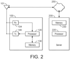
- the wireless communication device 100 further comprises a receiver 104 (including an RF front-end and a signal processing unit not shown in the diagram), a processor 120, a memory 130, and a transmitter 140.
- the RF front-end is configured to receive GNSS signals via the antenna 101, and to output them to the signal processing unit.
- the RF front-end is configured to down-convert and digitise the satellite signals received via the antenna 101.
- the RF front-end essentially conditions the signals for subsequent signal processing. Other typical tasks performed by the front-end include filtering and amplification.
- the satellite signals received at the RF front-end via the antenna 101 include (when available) at least one ranging signal, such as a GPS L1 C/A signal, for each of a plurality of satellites.
- the signal processing unit is configured to track the received GNSS signals - in particular, in frequency, delay (code-phase) and carrier phase - and to produce GNSS measurements from the received GNSS signals.
- the PRN sequences are chosen so that they have good autocorrelation properties and minimal cross-correlation between them.
- the DSSS reference signals are transmitted in the industrial, scientific and medical (ISM) band from 2.4 GHz to 2.5 GHz.
- the processor may additionally control the receiver 104 to receive (real) GNSS signals (see step 345).
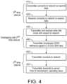
- Fig. 4 is a flowchart illustrating a method performed by a wireless communication device 100 operating as a virtual satellite, according to one example. In the context of Fig. 1 , this would be the method performed by the wireless communication devices 10-18, which transmit the ISM band DSSS reference signals. We will refer to the wireless communication device 10 by way of example.
- steps 430 and 440 occur in a time interval that overlaps at least partially with the second time interval.
- the second time interval is the time interval in which the receiver 104 of the "tag" wireless communication device 20 is listening to receive the virtual satellite signals. This means that both the transmitting "virtual satellite" wireless communication device 10 and the receiving "tag” wireless communication device 20 are in an idle (or inactive or offline) state with respect to the wireless infrastructure network during the period of overlap.
- the time interval during which the transmitter 140 is broadcasting the DSSS reference signal does not overlap with the fourth time interval.
- the server already knows the position of the wireless communication device 10 (for example, from a previous configuration phase). However, if this is not the case, then the data transmitted to the server may also include the position of the wireless communication device 10. The data transmitted to the server can be used by the server when calculating a position fix for the wireless communication device 20.
- the fifth time interval does not overlap with the time interval in which the transmitter is broadcasting the DSSS reference signal. However, the fifth time interval could overlap with (or be identical to) the fourth time interval. (This would mean that the fourth time interval occurs after the broadcasting time interval.)
- the wireless communication device 20 Over time, provided the wireless communication device 20 listens for long enough, it will receive the DSSS reference signals broadcast by all of the wireless communication devices 10-18 in its vicinity. To maximise the likelihood of receiving all of the DSSS reference signals in as short a time as possible, the transmitting wireless communication devices 10-18 should try to spend as long as possible broadcasting, and the listening wireless communication device 20 should try to spend as long as possible listening. Note that it is assumed that the wireless communication devices 10-18 are static, and the wireless communication device 20 is either stationary, or moving sufficiently slowly (and using a sufficiently short measurement epoch) that it can be treated as stationary for the purposes of the positioning measurements without compromising the desired accuracy.
- the listening wireless communication device 20 of the present example receives and measures the signals sequentially until it has enough measurements to calculate a position. Nevertheless, the measurements should be made over a short enough time interval that the device has not moved significantly between the first and the last of the signal measurements used to calculate the position. If the wireless communication device 20 is moving faster than this (relative to the time interval spanning the measurements), then the accuracy of the position estimate is likely to be reduced.
- the "virtual satellite” devices 10-18 and the “tag” device 20 are identical in terms of their hardware components. That is, each wireless communication device is adapted to perform the functions of both a virtual satellite device and a tag device. Consequently, each device is capable of performing all the steps of Fig. 3 , as well as all of the steps of Fig. 4 .
- the only difference between the devices is their configuration.
- the wireless communication device 20 that is intended to operate as a tag device is configured in software to do so.
- the wireless communication devices 10-18 that are intended to operate as virtual satellites are configured in software to do so. Any of the devices could be reconfigured to perform the "opposite" function from the one it was originally configured to do. That is, the wireless communication devices 10-18 are reconfigurable to be tag devices and the wireless communication device 20 is reconfigurable to be a virtual satellite. (As will be explained in greater detail later below, this flexibility and functionality can be useful in particular in a configuration phase.)
- the processor of the wireless communication device 20 will need to know the positions of the wireless communication devices 10-18 operating as virtual satellites. These positions can be provided to it as assistance information, via the cellular network (in particular, via the base station) or at production or as an offline software update.
- the positions of the wireless communication devices 10-18 operating as virtual satellites can be obtained by various means. It is assumed that these devices do not move once they have been installed and commissioned. In some examples, they may be placed in known positions, and those positions may be provided manually (for example, by an engineer commissioning the system). However, in some examples, the virtual satellites may be distributed in unknown positions. It may be desirable to determine these positions automatically, in a configuration phase.
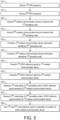
- Fig. 5 is a flowchart illustrating a method performed in a configuration phase, according to an example. In this phase, let us assume that the tag device 20 is not yet present.
- the server 200 chooses a first PRN sequence for use by a first wireless communication device 10.
- the server 200 chooses a second PRN sequence for use by a second wireless communication device 12. Both wireless communication devices 10 and 12 are intended to operate as virtual satellites, once the system has been commissioned.
- the server instructs the first wireless communication device to transmit a DSSS reference signal using a spreading code defined by the first PRN sequence.
- the server 200 instructs the second wireless communication device to transmit a DSSS reference signal using a spreading code defined by the second PRN sequence.
- These instructions are communicated to the respective wireless communication devices via the network 250.
- the final link in the communications chain is from the base station 30 to each wireless communication device 10, 12. That is, the instructions are ultimately sent as data messages over the wireless infrastructure network.
- the server 200 provides the first wireless communication device 10 with information identifying the second PRN sequence.
- the first wireless communication device 10 will use this information to enable it to detect and measure the code phase of the DSSS reference signal broadcast by the second wireless communication device 12.
- the server 200 provides the second wireless communication device 12 with information identifying the first PRN sequence.
- the second wireless communication device 12 will use this information to enable it to detect and measure the code phase of the DSSS reference signal broadcast by the first wireless communication device 10.
- the first wireless communication device 10 transmits its DSSS reference signal (based on the first PRN sequence).
- the second wireless communication device 12 transmits its DSSS reference signal (based on the second PRN sequence).
- the receiver 104 of the second wireless communication device 12 is controlled to measure the code phase of the first spreading code, in the signal received at the second wireless communication device 12 from the first wireless communication device 10.
- the receiver 104 of the first wireless communication device 10 is controlled to measure the code phase of the second spreading code, in the signal received at the first wireless communication device 10 from the second wireless communication device 12.
- each wireless communication device 10-18 may be configured to broadcast its DSSS reference signal in the ISM band in a different timeslot.
- the timeslots may be allocated by the server 200 in advance.
- the round-trip measurements are repeated for each pair of wireless communication devices in the set 10-18.
- Each code phase measurement, made by each wireless communication device is reported to the server 200 via the wireless infrastructure network (and network 250).
- the server 200 can calculate the positions of the wireless communication devices 10-18 relative to one another (step 560).
- the position of one device may be input manually.
- at least one of the wireless communication devices 10-18 can be positioned at a location where it has a good view of the sky, enabling it to receive GNSS signals. Its absolute position can then be calculated from GNSS measurements made from these GNSS signals. The calculation can be performed either by the processor of the wireless communication device in question, or by the server 200 (by reporting the GNSS measurements to the server 200).
- the processor of each of the wireless communication devices 10-18 (configured to operate as virtual satellites) reconfigures itself to deactivate the "listening" mode in which it received and measured the code phases of virtual satellite signals from other wireless communication devices. This is because, during the normal operation of the system, once configured, there is no need for virtual satellites to measure the reference signals of other virtual satellites. As the positions of the virtual satellite known and unchanging, at this stage, such measurements would not add any new information.
- tags in the local area can be configured with the information of each virtual satellite.
- the server 200 first determines the coarse position of each wireless communication device 20 operating as a tag. (Although just one such device is shown in Fig. 1 , it should be understood that typically there are many of them.)
- the wireless communication device 20 is able to make Doppler measurements from GNSS signals, its coarse position may be calculated from these measurements by methods known in the art.
- the particular set of spreading codes observed by the tag functions as a kind of "fingerprint" for the neighbourhood where the tag is located.
- the server 200 stores in its memory 230 a database of the locations of the virtual satellites and the respective spreading codes used by them (once they have been configured). The server 200 can consult this database to identify the coarse location of the tag, based on the set of spreading codes it observed. Even if the PRN codes used for the virtual satellites are not unique, the visibility of a specific set of PRN codes (fingerprint) allows to define without ambiguities both the coarse location of the tag and the identity of virtual satellites.
- GNSS Doppler measurements and/or spreading code fingerprinting can avoid the need for a database of base stations to be maintained at the server 200.
- the use of GNSS Doppler measurements also means that the coarse position can be established even when no virtual satellite is visible to the tag.
- the server After the server determines the coarse position of the wireless communication device 20 operating as a tag, it identifies the wireless communication devices 10-18 acting as virtual satellites, whose signals the wireless communication device 20 is likely to be able to receive at that coarse position. (This may already be apparent, in the case of the fingerprinting approach described above.)
- the server 200 Having identified the likely visible virtual satellites, the server 200 provides to the wireless communication device 20 with information identifying the spreading code to be used by each of the identified virtual satellites. It may also provide identity information of each virtual satellite and optionally the position of each virtual satellite. Once configured with this information, the wireless communication device 20 is ready to begin making measurements of the virtual satellite signals for use in the calculation of its position (for example, according to the method of Fig. 3 ).
- wireless communication devices were identical, in terms of their structure, hardware, and capabilities. They were (re-)configurable in software to fulfil different functions. Each device comprised the same hardware, and each was configurable to operate as either a tag or a virtual satellite. A device that was configured to operate as a tag, in one deployment, could be reconfigured to operate as a virtual satellite, in another deployment.
- wireless communication devices of different types could be used in the different roles. Some devices may be designed and adapted to operate only as virtual satellite devices; other devices may be designed and adapted to operate only as tag devices. In these cases, devices cannot be reconfigured to fulfil functions other than the ones for which they were designed.
- the transmitter of the tag devices might be simplified, since it does not need to be able to transmit a DSSS reference signal in the ISM band.
- the receiver of the virtual satellite device may be simplified, since it does not need to be able to receive and measure the code phase of a DSSS reference signal in the ISM band.
- carrier phase measurements could be used in addition to the code phase measurements.
- carrier phase will be familiar to those skilled in the art from its analogous use in GNSS positioning.
- Fig. 1 all of the wireless communication devices were in communication with (and being served by) the same base station 30. This is not essential. In other examples, different wireless communication devices may be served by different base stations. In some examples, different wireless communication devices may be served by base stations in different wireless infrastructure networks. Timing differences between different base stations or different wireless infrastructure networks may be monitored by ensuring that at least one wireless communication device is able to receive GNSS signals and calculate a position fix. This position fix can include a GNSS-derived estimate of UTC time, which can be used as a reference against which to compare the timings of the different base stations. The relevant timing offsets and optionally clock drifts can then be taken into account when calculating the position of the (or each) wireless communication device.
- This position fix can include a GNSS-derived estimate of UTC time, which can be used as a reference against which to compare the timings of the different base stations. The relevant timing offsets and optionally clock drifts can then be taken into account when calculating the position of the (or each) wireless communication device.
- wireless communication devices functioning as tags are battery-powered, and wireless communication devices functioning as virtual satellites are mains-powered.
- a single antenna 101 was shared between the receiver 104 and the transmitter 140. This was used for LTE/5G uplink and downlink signals, receiving GNSS signals, and transmitting and/or receiving direct sequence spread spectrum reference signals in a predefined ISM band. In other examples, more than one antenna be provided. Different antennas be used for different purposes (e.g., transmitting and receiving) and/or different frequency bands.
- a server may instruct all of the wireless communication devices 10-18 to enter an idle mode and broadcast their DSSS reference signals in the same time interval (according to their local clocks). This will align the time intervals to within an error that is determined by the variation among the local clocks.
- Fig. 1 it was assumed for the configuration phase that every wireless communication device 10-18 operating as a virtual satellite was able to receive the DSSS signal of every other such device. In general, this will not be the case (especially in large deployments). In the most general case, the only constraint is that the virtual satellites should be positioned densely enough so that a tag can receive enough signals for its position to be calculated. To enable self-configuration of the virtual satellites, they should be positioned densely enough that each virtual satellite can receive enough signals from other virtual satellites in order for the absolute positions of all of them to be calculated by the server 200 starting from the absolute position of at least one of them.
- the capture timestamp could optionally be transmitted to the server 200 by the tag, along with the code phase measurement (and possibly other signal measurements). This is correct.
- the timestamp is useful to assist the server to calculate the position of the tag.
- the code phase measurements and optional other signal measurements
- Fig. 2 may be implemented in hardware, or software, or a mixture of both. Furthermore, some components may be grouped together in a given implementation or may be implemented separately. In the present implementation, the RF front-end is implemented entirely in hardware, the signal processing unit is implemented partially in hardware, and the remaining components (downstream in the signal processing chain) are implemented in software. Other implementations are possible, which divide and distribute the various functions differently between hardware and software, or between different hardware components, software modules and/or processors running the software.
- any reference signs placed between parentheses shall not be construed as limiting the claim.
- the word “comprising” does not exclude the presence of elements or steps other than those listed in a claim. However, where the word “comprising” is used, this also discloses as a special case the possibility that the elements or steps listed are exhaustive - that is, the apparatus or method may consist solely of those elements or steps.
- the word “a” or “an” preceding an element does not exclude the presence of a plurality of such elements.
- the embodiments may be implemented by means of hardware comprising several distinct elements. In a device claim enumerating several means, several of these means may be embodied by one and the same item of hardware.
- the memory may be of any type suitable to the local technical environment and may be implemented using any suitable data storage technology, such as semiconductor-based memory devices, magnetic memory devices and systems, optical memory devices and systems, fixed memory and removable memory.
- the data processors may be of any type suitable to the local technical environment, and may include one or more of general purpose computers, special purpose computers, microprocessors, digital signal processors (DSPs), application specific integrated circuits (ASIC), gate level circuits and processors based on multi-core processor architecture, as non-limiting examples.
- Embodiments as discussed herein may be practiced in various components such as integrated circuit modules.
- the design of integrated circuits is generally a highly automated process. Complex and powerful software tools are available for converting a logic level design into a semiconductor circuit design ready to be etched and formed on a semiconductor substrate.
Landscapes
- Engineering & Computer Science (AREA)
- Radar, Positioning & Navigation (AREA)
- Remote Sensing (AREA)
- Computer Networks & Wireless Communication (AREA)
- Physics & Mathematics (AREA)
- General Physics & Mathematics (AREA)
- Signal Processing (AREA)
- Mobile Radio Communication Systems (AREA)
Priority Applications (3)
| Application Number | Priority Date | Filing Date | Title |
|---|---|---|---|
| EP23150801.1A EP4397987A1 (fr) | 2023-01-09 | 2023-01-09 | Positionnement avec des satellites virtuels |
| US18/403,983 US12546900B2 (en) | 2023-01-09 | 2024-01-04 | Positioning with virtual satellites |
| CN202410029845.7A CN118317421A (zh) | 2023-01-09 | 2024-01-09 | 利用虚拟卫星的定位 |
Applications Claiming Priority (1)
| Application Number | Priority Date | Filing Date | Title |
|---|---|---|---|
| EP23150801.1A EP4397987A1 (fr) | 2023-01-09 | 2023-01-09 | Positionnement avec des satellites virtuels |
Publications (1)
| Publication Number | Publication Date |
|---|---|
| EP4397987A1 true EP4397987A1 (fr) | 2024-07-10 |
Family
ID=84888860
Family Applications (1)
| Application Number | Title | Priority Date | Filing Date |
|---|---|---|---|
| EP23150801.1A Pending EP4397987A1 (fr) | 2023-01-09 | 2023-01-09 | Positionnement avec des satellites virtuels |
Country Status (3)
| Country | Link |
|---|---|
| US (1) | US12546900B2 (fr) |
| EP (1) | EP4397987A1 (fr) |
| CN (1) | CN118317421A (fr) |
Families Citing this family (2)
| Publication number | Priority date | Publication date | Assignee | Title |
|---|---|---|---|---|
| EP4283933B1 (fr) * | 2022-05-25 | 2026-04-29 | u-blox AG | Procédé pour la fourniture d'au moins un paramètre estimé d'un canal de communication sans fil et dispositif de récepteur radio |
| US20240373394A1 (en) * | 2023-05-01 | 2024-11-07 | Samsung Electronics Co., Ltd. | Systems and methods for sidelink positioning accuracy |
Citations (4)
| Publication number | Priority date | Publication date | Assignee | Title |
|---|---|---|---|---|
| US20180143328A1 (en) * | 2016-11-18 | 2018-05-24 | Centre National D'etudes Spatiales | Transmission of gnss signals using a radio communication network |
| CN108282748A (zh) * | 2018-03-13 | 2018-07-13 | 深圳市世纪本原科技股份有限公司 | 一种基于lora无线通信技术的定位跟踪方法及跟踪器 |
| US20200229124A1 (en) * | 2019-01-11 | 2020-07-16 | Qualcomm Incorporated | Network calibration with round-trip-time (rtt)-based positioning procedures |
| US20210041223A1 (en) * | 2018-02-07 | 2021-02-11 | Second Bridge Inc. | Electronic distance measurement equipment |
Family Cites Families (3)
| Publication number | Priority date | Publication date | Assignee | Title |
|---|---|---|---|---|
| US6389291B1 (en) * | 2000-08-14 | 2002-05-14 | Sirf Technology | Multi-mode global positioning system for use with wireless networks |
| US9155110B2 (en) * | 2013-03-27 | 2015-10-06 | Magnolia Broadband Inc. | System and method for co-located and co-channel Wi-Fi access points |
| WO2017113054A1 (fr) * | 2015-12-28 | 2017-07-06 | 华为技术有限公司 | Procédé, dispositif et système de positionnement au sol |
-
2023
- 2023-01-09 EP EP23150801.1A patent/EP4397987A1/fr active Pending
-
2024
- 2024-01-04 US US18/403,983 patent/US12546900B2/en active Active
- 2024-01-09 CN CN202410029845.7A patent/CN118317421A/zh active Pending
Patent Citations (4)
| Publication number | Priority date | Publication date | Assignee | Title |
|---|---|---|---|---|
| US20180143328A1 (en) * | 2016-11-18 | 2018-05-24 | Centre National D'etudes Spatiales | Transmission of gnss signals using a radio communication network |
| US20210041223A1 (en) * | 2018-02-07 | 2021-02-11 | Second Bridge Inc. | Electronic distance measurement equipment |
| CN108282748A (zh) * | 2018-03-13 | 2018-07-13 | 深圳市世纪本原科技股份有限公司 | 一种基于lora无线通信技术的定位跟踪方法及跟踪器 |
| US20200229124A1 (en) * | 2019-01-11 | 2020-07-16 | Qualcomm Incorporated | Network calibration with round-trip-time (rtt)-based positioning procedures |
Also Published As
| Publication number | Publication date |
|---|---|
| US12546900B2 (en) | 2026-02-10 |
| US20240230919A1 (en) | 2024-07-11 |
| CN118317421A (zh) | 2024-07-09 |
Similar Documents
| Publication | Publication Date | Title |
|---|---|---|
| US12546900B2 (en) | Positioning with virtual satellites | |
| JP5957025B2 (ja) | ユーザ受信機の位置決定方法 | |
| CN104880185B (zh) | 用于低复杂性地理定位的协作型位置传感器设备及系统 | |
| US7952518B2 (en) | Internet hotspots localization using satellite systems | |
| US8179312B2 (en) | Precise absolute time transfer from a satellite system | |
| US6389291B1 (en) | Multi-mode global positioning system for use with wireless networks | |
| EP1262790B1 (fr) | Procédé et dispositif de détermination de temps pour récepteurs GPS | |
| US9684080B2 (en) | Low-energy GPS | |
| US9651675B2 (en) | Estimating frequency of a GNSS enabled device based on time stamps | |
| US9213103B2 (en) | Cells obtaining timing and positioning by using satellite systems with high power signals for improved building penetration | |
| CN108076445B (zh) | 使用无线通信网络的gnss信号传输 | |
| US20110163914A1 (en) | Gps with aiding from ad-hoc peer-to-peer bluetooth networks | |
| US20090251364A1 (en) | Method and system of a mobile subscriber estimating position | |
| US20040192345A1 (en) | Methods, systems and computer program products for providing location determination information to an assisted location service | |
| US20110207472A1 (en) | Method and system for cellular clock-assisted wireless access point locating | |
| CN105071914A (zh) | 基于数字调频广播的时钟同步方法和调频广播接收机 | |
| KR101497592B1 (ko) | 실내 항법 서비스를 제공하는 방법, 의사위성 및 시스템 | |
| KR20010051654A (ko) | 타이밍 측정 방법 | |
| KR20250050037A (ko) | 무선 통신 시스템에서 단말이 측정을 수행하는 방법 및 이를 위한 장치 | |
| Meiyappan et al. | Position, Navigation and Timing with Dedicated Metropolitan Beacon Systems | |
| WO2005025249A1 (fr) | Procede permettant de reduire au minimum l'incertitude de temps systeme maximum pour une station mobile | |
| CN121418979A (zh) | 通信方法及通信装置 | |
| AU2015201173B2 (en) | Internet hotspots localization using satellite systems | |
| HK1024060B (en) | Method and apparatus for determining time for gps receivers | |
| HK1126281A (en) | Method and apparatus for determining time for gps receivers |
Legal Events
| Date | Code | Title | Description |
|---|---|---|---|
| PUAI | Public reference made under article 153(3) epc to a published international application that has entered the european phase |
Free format text: ORIGINAL CODE: 0009012 |
|
| STAA | Information on the status of an ep patent application or granted ep patent |
Free format text: STATUS: THE APPLICATION HAS BEEN PUBLISHED |
|
| AK | Designated contracting states |
Kind code of ref document: A1 Designated state(s): AL AT BE BG CH CY CZ DE DK EE ES FI FR GB GR HR HU IE IS IT LI LT LU LV MC ME MK MT NL NO PL PT RO RS SE SI SK SM TR |
|
| P01 | Opt-out of the competence of the unified patent court (upc) registered |
Free format text: CASE NUMBER: APP_44617/2024 Effective date: 20240731 |
|
| STAA | Information on the status of an ep patent application or granted ep patent |
Free format text: STATUS: REQUEST FOR EXAMINATION WAS MADE |
|
| 17P | Request for examination filed |
Effective date: 20250110 |