EP4398021A2 - Unité d'éclairage avec de multiples sources de lumière pour générer un point d'éclairage uniforme - Google Patents
Unité d'éclairage avec de multiples sources de lumière pour générer un point d'éclairage uniforme Download PDFInfo
- Publication number
- EP4398021A2 EP4398021A2 EP24170457.6A EP24170457A EP4398021A2 EP 4398021 A2 EP4398021 A2 EP 4398021A2 EP 24170457 A EP24170457 A EP 24170457A EP 4398021 A2 EP4398021 A2 EP 4398021A2
- Authority
- EP
- European Patent Office
- Prior art keywords
- axis
- light source
- illumination unit
- reflector
- light
- Prior art date
- Legal status (The legal status is an assumption and is not a legal conclusion. Google has not performed a legal analysis and makes no representation as to the accuracy of the status listed.)
- Pending
Links
Images



Classifications
-
- G—PHYSICS
- G01—MEASURING; TESTING
- G01J—MEASUREMENT OF INTENSITY, VELOCITY, SPECTRAL CONTENT, POLARISATION, PHASE OR PULSE CHARACTERISTICS OF INFRARED, VISIBLE OR ULTRAVIOLET LIGHT; COLORIMETRY; RADIATION PYROMETRY
- G01J3/00—Spectrometry; Spectrophotometry; Monochromators; Measuring colours
- G01J3/02—Details
- G01J3/0205—Optical elements not provided otherwise, e.g. optical manifolds, diffusers, windows
- G01J3/0229—Optical elements not provided otherwise, e.g. optical manifolds, diffusers, windows using masks, aperture plates, spatial light modulators or spatial filters, e.g. reflective filters
-
- G—PHYSICS
- G01—MEASURING; TESTING
- G01J—MEASUREMENT OF INTENSITY, VELOCITY, SPECTRAL CONTENT, POLARISATION, PHASE OR PULSE CHARACTERISTICS OF INFRARED, VISIBLE OR ULTRAVIOLET LIGHT; COLORIMETRY; RADIATION PYROMETRY
- G01J3/00—Spectrometry; Spectrophotometry; Monochromators; Measuring colours
- G01J3/02—Details
- G01J3/0256—Compact construction
-
- G—PHYSICS
- G01—MEASURING; TESTING
- G01J—MEASUREMENT OF INTENSITY, VELOCITY, SPECTRAL CONTENT, POLARISATION, PHASE OR PULSE CHARACTERISTICS OF INFRARED, VISIBLE OR ULTRAVIOLET LIGHT; COLORIMETRY; RADIATION PYROMETRY
- G01J3/00—Spectrometry; Spectrophotometry; Monochromators; Measuring colours
- G01J3/02—Details
- G01J3/0291—Housings; Spectrometer accessories; Spatial arrangement of elements, e.g. folded path arrangements
-
- G—PHYSICS
- G01—MEASURING; TESTING
- G01J—MEASUREMENT OF INTENSITY, VELOCITY, SPECTRAL CONTENT, POLARISATION, PHASE OR PULSE CHARACTERISTICS OF INFRARED, VISIBLE OR ULTRAVIOLET LIGHT; COLORIMETRY; RADIATION PYROMETRY
- G01J3/00—Spectrometry; Spectrophotometry; Monochromators; Measuring colours
- G01J3/02—Details
- G01J3/10—Arrangements of light sources specially adapted for spectrometry or colorimetry
-
- G—PHYSICS
- G01—MEASURING; TESTING
- G01N—INVESTIGATING OR ANALYSING MATERIALS BY DETERMINING THEIR CHEMICAL OR PHYSICAL PROPERTIES
- G01N21/00—Investigating or analysing materials by the use of optical means, i.e. using sub-millimetre waves, infrared, visible or ultraviolet light
- G01N21/17—Systems in which incident light is modified in accordance with the properties of the material investigated
- G01N21/25—Colour; Spectral properties, i.e. comparison of effect of material on the light at two or more different wavelengths or wavelength bands
- G01N21/255—Details, e.g. use of specially adapted sources, lighting or optical systems
-
- G—PHYSICS
- G01—MEASURING; TESTING
- G01N—INVESTIGATING OR ANALYSING MATERIALS BY DETERMINING THEIR CHEMICAL OR PHYSICAL PROPERTIES
- G01N21/00—Investigating or analysing materials by the use of optical means, i.e. using sub-millimetre waves, infrared, visible or ultraviolet light
- G01N21/17—Systems in which incident light is modified in accordance with the properties of the material investigated
- G01N21/25—Colour; Spectral properties, i.e. comparison of effect of material on the light at two or more different wavelengths or wavelength bands
- G01N21/27—Colour; Spectral properties, i.e. comparison of effect of material on the light at two or more different wavelengths or wavelength bands using photo-electric detection ; circuits for computing concentration
- G01N21/274—Calibration, base line adjustment, drift correction
-
- G—PHYSICS
- G01—MEASURING; TESTING
- G01N—INVESTIGATING OR ANALYSING MATERIALS BY DETERMINING THEIR CHEMICAL OR PHYSICAL PROPERTIES
- G01N21/00—Investigating or analysing materials by the use of optical means, i.e. using sub-millimetre waves, infrared, visible or ultraviolet light
- G01N21/17—Systems in which incident light is modified in accordance with the properties of the material investigated
- G01N21/25—Colour; Spectral properties, i.e. comparison of effect of material on the light at two or more different wavelengths or wavelength bands
- G01N21/31—Investigating relative effect of material at wavelengths characteristic of specific elements or molecules, e.g. atomic absorption spectrometry
-
- G—PHYSICS
- G01—MEASURING; TESTING
- G01N—INVESTIGATING OR ANALYSING MATERIALS BY DETERMINING THEIR CHEMICAL OR PHYSICAL PROPERTIES
- G01N33/00—Investigating or analysing materials by specific methods not covered by groups G01N1/00 - G01N31/00
- G01N33/48—Biological material, e.g. blood, urine; Haemocytometers
- G01N33/483—Physical analysis of biological material
- G01N33/487—Physical analysis of biological material of liquid biological material
- G01N33/49—Blood
- G01N33/491—Blood by separating the blood components
-
- G—PHYSICS
- G02—OPTICS
- G02B—OPTICAL ELEMENTS, SYSTEMS OR APPARATUS
- G02B27/00—Optical systems or apparatus not provided for by any of the groups G02B1/00 - G02B26/00, G02B30/00
- G02B27/10—Beam splitting or combining systems
- G02B27/14—Beam splitting or combining systems operating by reflection only
- G02B27/143—Beam splitting or combining systems operating by reflection only using macroscopically faceted or segmented reflective surfaces
-
- G—PHYSICS
- G02—OPTICS
- G02B—OPTICAL ELEMENTS, SYSTEMS OR APPARATUS
- G02B5/00—Optical elements other than lenses
- G02B5/005—Diaphragms
-
- G—PHYSICS
- G01—MEASURING; TESTING
- G01J—MEASUREMENT OF INTENSITY, VELOCITY, SPECTRAL CONTENT, POLARISATION, PHASE OR PULSE CHARACTERISTICS OF INFRARED, VISIBLE OR ULTRAVIOLET LIGHT; COLORIMETRY; RADIATION PYROMETRY
- G01J3/00—Spectrometry; Spectrophotometry; Monochromators; Measuring colours
- G01J3/02—Details
- G01J3/10—Arrangements of light sources specially adapted for spectrometry or colorimetry
- G01J2003/102—Plural sources
-
- G—PHYSICS
- G01—MEASURING; TESTING
- G01N—INVESTIGATING OR ANALYSING MATERIALS BY DETERMINING THEIR CHEMICAL OR PHYSICAL PROPERTIES
- G01N21/00—Investigating or analysing materials by the use of optical means, i.e. using sub-millimetre waves, infrared, visible or ultraviolet light
- G01N21/17—Systems in which incident light is modified in accordance with the properties of the material investigated
- G01N21/25—Colour; Spectral properties, i.e. comparison of effect of material on the light at two or more different wavelengths or wavelength bands
- G01N21/31—Investigating relative effect of material at wavelengths characteristic of specific elements or molecules, e.g. atomic absorption spectrometry
- G01N21/314—Investigating relative effect of material at wavelengths characteristic of specific elements or molecules, e.g. atomic absorption spectrometry with comparison of measurements at specific and non-specific wavelengths
- G01N2021/3144—Investigating relative effect of material at wavelengths characteristic of specific elements or molecules, e.g. atomic absorption spectrometry with comparison of measurements at specific and non-specific wavelengths for oxymetry
-
- G—PHYSICS
- G01—MEASURING; TESTING
- G01N—INVESTIGATING OR ANALYSING MATERIALS BY DETERMINING THEIR CHEMICAL OR PHYSICAL PROPERTIES
- G01N2201/00—Features of devices classified in G01N21/00
- G01N2201/06—Illumination; Optics
- G01N2201/061—Sources
-
- G—PHYSICS
- G01—MEASURING; TESTING
- G01N—INVESTIGATING OR ANALYSING MATERIALS BY DETERMINING THEIR CHEMICAL OR PHYSICAL PROPERTIES
- G01N2201/00—Features of devices classified in G01N21/00
- G01N2201/06—Illumination; Optics
- G01N2201/062—LED's
-
- G—PHYSICS
- G01—MEASURING; TESTING
- G01N—INVESTIGATING OR ANALYSING MATERIALS BY DETERMINING THEIR CHEMICAL OR PHYSICAL PROPERTIES
- G01N2201/00—Features of devices classified in G01N21/00
- G01N2201/06—Illumination; Optics
- G01N2201/063—Illuminating optical parts
- G01N2201/0636—Reflectors
-
- G—PHYSICS
- G01—MEASURING; TESTING
- G01N—INVESTIGATING OR ANALYSING MATERIALS BY DETERMINING THEIR CHEMICAL OR PHYSICAL PROPERTIES
- G01N2201/00—Features of devices classified in G01N21/00
- G01N2201/12—Circuits of general importance; Signal processing
- G01N2201/127—Calibration; base line adjustment; drift compensation
Definitions
- the present disclosure relates to an illumination unit with multiple light sources for generating a uniform illumination spot.
- Various types of tests related to patient diagnosis and therapy can be performed by analysis of a sample, such as a patient's bodily fluids. These tests typically use automated sample analyzers onto which vials containing samples have been loaded. The sample analyzer extracts the samples from the vials and combines the samples with various reagents in reaction vessels. Frequently, the samples are incubated or otherwise processed before being analyzed. Such sample analyzers obtain measurements from the sample in order to determine the presence and/or amount of analyte of interest.
- analytical clinical technology is challenged by increasing needs for improved levels of analysis. The improvement of analytical sensitivity continues to be a challenge.
- Typical sample analyzers use an optical system during the test procedure to obtain readings from the sample.
- a typical optical system has an aligned light source and a detector (e.g. spectrophotometer).
- the sample vessel contains the sample and a reagent and is positioned between the light source and detector along an optical axis centerline of the light source.
- the light source emits light into the input region into the sample-reagent combination inside the vessel.
- a chemical reaction of the sample-reagent combination produces chromophores absorbing light at specific wavelengths proportional to the concentration of the analyte being measured. Light emitted from the illuminated sample-reagent combination inside the vessel exits the output region and is detected by the detector.
- the detector obtains an absorbance measurement of the emitted light signal at specific wavelengths following the Beer-Lambert law.
- other readings may be obtained, such as turbidimetric, fluorometric and like readings.
- the obtained readings are used to determine an amount of analyte in the sample using well-known calibration techniques.
- An embodiment of the present disclosure is an illumination unit.
- the illumination unit includes a housing assembly that defines an internal space.
- the illumination unit includes a first light source mounted to the housing assembly in the internal space.
- the first light source is positioned on a first axis.
- the illumination system includes a second light source mounted to the housing assembly in the internal space on a second axis that intersects and is angularly offset with respect to the first axis.
- the illumination unit includes a reflector in the internal space of the housing assembly, the reflector including an aperture through which the first axis extends and a reflective surface angled with respect to the first axis and the second axis, and an optional lens positioned in the housing assembly and positioned on the first axis opposite the reflector.
- the illumination unit includes a first light source positioned on a first axis and a second light source positioned on a second axis that intersects and is angularly offset with respect to the first axis.
- the illumination unit also includes a reflector positioned on the first and second axes.
- the reflector has an elliptical aperture through which the first axis extends and a reflective surface. The reflective surface is angled with respect to the first axis and the second axis such that light traveling from the first light source through the elliptical aperture creates a circular beam of light on a target positioned on the first axis opposite the first light source relative to the reflector.
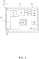
- embodiments of the present disclosure include an illumination unit that may be used within a sample analysis system 10 adapted to analyze a sample S. While the illumination unit is described below with respect to a sample analysis system, the illumination unit may have other applications and uses.
- the sample analysis system 10 includes a sample analyzer 12 and a sample vessel V.
- the sample vessel V is designed to hold a sample S for analysis by the sample analyzer 12 as will be detailed further below.
- the sample S can be any type of liquid.
- the sample S can be a biological sample or body fluid, such as blood, plasma, urine, or other fluids obtained from a patient.
- the sample S may also include non-biological sample liquids.
- the sample S is not limited strictly to liquids obtained from the patient.
- the illumination unit is configured to generate a substantially uniform light spot on a target T.
- the target T could be a sample vessel V as shown.
- the uniform light spot may be generated by using multiple sources of light, offset with respect to each other, as will be described further below.
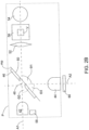
- the detection unit 40 includes an illumination unit 41.
- the illumination unit 41 may include multiple lights sources 42 and 44, a reflector 46, and at least one lens 52. It should be appreciated that in some embodiments, the illumination unit 41 may not include a lens 52. Accordingly, the lens 52 is an optional component. In one example, the illumination unit 41 may be self-contained, e.g. in a separate housing, in order to be easily removed from the sample analyzer 12.
- the illumination unit 41 includes a first light source 42 on the first axis A1 and a second light source 44 on a second axis A2 that intersects and is angularly offset with respect to the first axis A1,
- the first light source 42 is configured to emit a first light signal S1 along the first axis A1
- the second light source 44 is configured to emit a second light signal S2 along the second axis A2.
- the first axis A1 and the second axis A2 intersect at about 90 degrees.
- the positions of the first and second light sources may be different from 90 degrees as will be further detailed below.
- the first light source may be a light emitting diode and the second light source may be a neon lamp.
- the illumination unit 41 also includes a reflector 46.
- the reflector 46 has an aperture 48 through which the first optical axis A1 extends, and a reflective surface 50 that is angled with respect to the first axis A1 and the second axis A2.
- a lens 52 is positioned on the first optical axis A1 opposite the reflector 46. One lens is shown but more may be included, or as discussed above, no lens may be included.
- a detector 54 may be aligned with the lens 52 on the first axis A1 and spaced from the lens 52 as shown. While the detector 54 is shown adjacent the lens 52, the detector 54 may be in located in other positions, consistent with teachings of the present disclosure. Furthermore, the detector 54 may be separate from the illumination unit 41 or a component of it.
- the detector 54 may be a spectrophotometer as is known in the art.
- the reflector 46 has a body 70 which includes the reflective surface 50.
- the aperture 48 is defined by the body 70 of the reflector 46 and extends entirely through the body 70.
- the reflective surface 50 lies along a reflector plane MP.
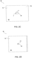
- the aperture 48 when viewed from a position parallel to the reflector plane MP, the aperture 48 has an elliptical shape. Accordingly, the body 70 may define a major dimension X of the aperture 48 and a minor dimension Y of the aperture 48 that is perpendicular to and intersects the major dimension X.
- the size of the elliptical aperture may vary with the major dimension X ranging between 0.5 mm up to 5 mm and the minor dimension Y ranging between 0.5 mm up to 4.0 mm. It should be appreciated that these ranges are not limiting and that both major and minor dimensions may be more than the lower limits or higher than the upper limits disclosed above.
- the reflector 46 is positioned in the illumination unit, the reflector 46 is angled with respect to the first light source 42. As can be seen in Figure 2D , when the reflector 46 is angled in this manner, such that first axis A1 extends through the aperture 48 and is angled with respect to reflector plane MP, the observable shape of the aperture 48 is circular.
- a sample vessel holder 56 may be included that is configured to hold a sample vessel V.
- the sample vessel holder 56 is located adjacent the detector 54 on the first optical axis A1, However, the sample holder 56 and detector 54 may be arranged in configurations other than those specifically shown in the drawings.
- the first and second light sources 42 and 44 emit light into the sample in the vessel V and the detector 54 detects the luminescence of the sample S that exits sample vessel V.
- a light sensor 58 is positioned proximate the first light source 42 and is configured to monitor the intensity of the first light signal S1 emitted from the first light source 42.
- the illumination unit 41 may include another reflector 60 positioned adjacent to the second light source 44 opposite the reflector 46.
- the illumination unit 41 may include an optional filter and a polarizer (not shown).
- the first light source 42, the second light source 44, and the reflector 46 may be arranged with respect to each other to generate a uniform spot illumination on the target Tin operation.
- the first light source 42, the second light source 44, the reflector 46 lie along a common plane P that includes the first axis A1 and the second axis A2.
- the first axis A1 and the second axis A2 intersect to define an angle ⁇ 1.
- angle ⁇ 1 is between 45 degrees and 135 degrees.
- the angle ⁇ 1 is between 75 degree and 105 degrees.
- the angle ⁇ 1 is about 90 degrees.
- the reflector 46 is angled with respect to the first and second light sources 42 and 44 to direct emitted light toward the target T.
- the reflective surface 50 is disposed along the reflector plane MP.
- the reflector plane MP and the first axis A1 define a first reflector angle ⁇ 2 that is less than about 90 degrees. In one example, the first angle is between 15 degrees and 75 degrees. In one example, the first reflector angle ⁇ 2 is about 45 degrees.
- the reflector plane MP and the second axis A2 define a second reflector angle ⁇ 3 that is less than about 90 degrees. In one example, the second reflector angle ⁇ 3 is between 15 degrees and 75 degrees. In one example, the second reflector angle ⁇ 3 is about 45 degrees.
- the sum of the first reflector angle ⁇ 2 and the second reflector angle ⁇ 3 may be about 90 degrees in one example. However, this sum may vary based on the position of the first and second light sources 42 and 44. It should be appreciated that the first reflector angle ⁇ 2 and the second reflector angle ⁇ 3 are related. As one angle increases, the other angle decreases, depending on the arrangement of the first and second light sources 42 and 44. It should be appreciated that that this configuration permits multiple light sources to be mounted on the same printed circuit board (PCB)with the reflector 46. This in turn, can permit designs with removable housings that would allow for easy and simple replacement of the illumination unit as needed.
- PCB printed circuit board
- the invention as described in the present disclosure is capable of exploitation in industry in accordance with how it can be made and/or used.
Landscapes
- Physics & Mathematics (AREA)
- Spectroscopy & Molecular Physics (AREA)
- General Physics & Mathematics (AREA)
- Health & Medical Sciences (AREA)
- Life Sciences & Earth Sciences (AREA)
- Chemical & Material Sciences (AREA)
- Engineering & Computer Science (AREA)
- Pathology (AREA)
- Biochemistry (AREA)
- Immunology (AREA)
- General Health & Medical Sciences (AREA)
- Analytical Chemistry (AREA)
- Biomedical Technology (AREA)
- Hematology (AREA)
- Optics & Photonics (AREA)
- Medicinal Chemistry (AREA)
- Food Science & Technology (AREA)
- Biophysics (AREA)
- Urology & Nephrology (AREA)
- Ecology (AREA)
- Molecular Biology (AREA)
- Mathematical Physics (AREA)
- Theoretical Computer Science (AREA)
- Investigating Or Analysing Materials By Optical Means (AREA)
- Non-Portable Lighting Devices Or Systems Thereof (AREA)
- Arrangement Of Elements, Cooling, Sealing, Or The Like Of Lighting Devices (AREA)
Applications Claiming Priority (3)
| Application Number | Priority Date | Filing Date | Title |
|---|---|---|---|
| US201862666913P | 2018-05-04 | 2018-05-04 | |
| PCT/US2019/030549 WO2019213484A1 (fr) | 2018-05-04 | 2019-05-03 | Unité d'éclairage avec de multiples sources de lumière pour générer un point d'éclairage uniforme |
| EP19795795.4A EP3788330B1 (fr) | 2018-05-04 | 2019-05-03 | Analyseur spectral d'échantillons avec une unité d'éclairage à plusieurs sources lumineuses |
Related Parent Applications (2)
| Application Number | Title | Priority Date | Filing Date |
|---|---|---|---|
| EP19795795.4A Division EP3788330B1 (fr) | 2018-05-04 | 2019-05-03 | Analyseur spectral d'échantillons avec une unité d'éclairage à plusieurs sources lumineuses |
| EP19795795.4A Division-Into EP3788330B1 (fr) | 2018-05-04 | 2019-05-03 | Analyseur spectral d'échantillons avec une unité d'éclairage à plusieurs sources lumineuses |
Publications (2)
| Publication Number | Publication Date |
|---|---|
| EP4398021A2 true EP4398021A2 (fr) | 2024-07-10 |
| EP4398021A3 EP4398021A3 (fr) | 2024-09-11 |
Family
ID=68386190
Family Applications (2)
| Application Number | Title | Priority Date | Filing Date |
|---|---|---|---|
| EP24170457.6A Pending EP4398021A3 (fr) | 2018-05-04 | 2019-05-03 | Unité d'éclairage avec de multiples sources de lumière pour générer un point d'éclairage uniforme |
| EP19795795.4A Active EP3788330B1 (fr) | 2018-05-04 | 2019-05-03 | Analyseur spectral d'échantillons avec une unité d'éclairage à plusieurs sources lumineuses |
Family Applications After (1)
| Application Number | Title | Priority Date | Filing Date |
|---|---|---|---|
| EP19795795.4A Active EP3788330B1 (fr) | 2018-05-04 | 2019-05-03 | Analyseur spectral d'échantillons avec une unité d'éclairage à plusieurs sources lumineuses |
Country Status (7)
| Country | Link |
|---|---|
| US (2) | US11262294B2 (fr) |
| EP (2) | EP4398021A3 (fr) |
| JP (1) | JP7336460B2 (fr) |
| CA (1) | CA3099111C (fr) |
| IL (1) | IL278347B2 (fr) |
| MX (1) | MX2020011688A (fr) |
| WO (1) | WO2019213484A1 (fr) |
Families Citing this family (3)
| Publication number | Priority date | Publication date | Assignee | Title |
|---|---|---|---|---|
| EP4164490B1 (fr) * | 2020-06-11 | 2026-01-07 | Siemens Healthcare Diagnostics, Inc. | Procédé et analyseur pour corriger des interférences inconnues dans l'échantillon sanguin d'un patient |
| US12535357B2 (en) | 2020-08-03 | 2026-01-27 | Siemens Healthcare Diagnostics Inc. | Absorbance spectroscopy analyzer and method of use |
| JP7576192B2 (ja) * | 2022-07-29 | 2024-10-30 | 中国科学院光電技術研究所 | 照明視野の不均一性検知システム、検知方法、補正方法および装置 |
Citations (4)
| Publication number | Priority date | Publication date | Assignee | Title |
|---|---|---|---|---|
| US5340716A (en) | 1991-06-20 | 1994-08-23 | Snytex (U.S.A.) Inc. | Assay method utilizing photoactivated chemiluminescent label |
| US5709994A (en) | 1992-07-31 | 1998-01-20 | Syntex (U.S.A.) Inc. | Photoactivatable chemiluminescent matrices |
| US5807675A (en) | 1993-09-03 | 1998-09-15 | Behringwerke Ag | Fluorescent oxygen channeling immunoassays |
| US20100150779A1 (en) | 2003-07-18 | 2010-06-17 | Siemens Healthcare Diagnostics Inc. | Automated Analyzer |
Family Cites Families (18)
| Publication number | Priority date | Publication date | Assignee | Title |
|---|---|---|---|---|
| US6008889A (en) | 1997-04-16 | 1999-12-28 | Zeng; Haishan | Spectrometer system for diagnosis of skin disease |
| JP2000097657A (ja) * | 1998-09-21 | 2000-04-07 | Nikon Corp | 干渉計 |
| IL131284A (en) * | 1999-08-05 | 2003-05-29 | Orbotech Ltd | Illumination for inspecting surfaces of articles |
| US6739739B2 (en) | 2002-06-13 | 2004-05-25 | Benq Corporation | Flash tube reflector |
| DE10227119A1 (de) * | 2002-06-15 | 2004-01-15 | Carl Zeiss Jena Gmbh | Optische Anordnung zur Gewinnung von Informationen von einer Probe oder einem Beobachtungsobjekt |
| US7429495B2 (en) * | 2002-08-07 | 2008-09-30 | Chang-Feng Wan | System and method of fabricating micro cavities |
| US20060215958A1 (en) * | 2004-11-17 | 2006-09-28 | Yeo Terence E | Enhanced electroluminescent sign |
| JP5056362B2 (ja) | 2007-02-06 | 2012-10-24 | 株式会社デンソーウェーブ | レーザレーダ装置 |
| EP1987762A1 (fr) * | 2007-05-03 | 2008-11-05 | F.Hoffmann-La Roche Ag | Oxymetre |
| DE102008056490A1 (de) | 2007-11-07 | 2009-05-14 | Carl Zeiss Meditec Ag | Applikator für ein ophthalmologisches Behandlungsgerät |
| JP2011175735A (ja) * | 2008-06-27 | 2011-09-08 | Abel Systems Inc | 光加算装置 |
| DE102011077327B4 (de) | 2011-06-09 | 2022-03-03 | Carl Zeiss Microscopy Gmbh | Lichtrastermikroskop mit Strahlkombinierer zum Kombinieren von zwei jeweils eigenständig gescannten Beleuchtungsstrahlen |
| CN102411205B (zh) | 2011-08-29 | 2015-04-08 | 深圳市绎立锐光科技开发有限公司 | 光源、合光装置及带该光源的投影装置 |
| JP5824984B2 (ja) * | 2011-09-06 | 2015-12-02 | 株式会社島津製作所 | 太陽電池セル検査装置 |
| WO2014109126A1 (fr) * | 2013-01-11 | 2014-07-17 | 富士電機株式会社 | Analyseur de gaz de type laser |
| KR102345537B1 (ko) * | 2014-12-11 | 2021-12-30 | 삼성전자주식회사 | 플라즈마 광원, 및 그 광원을 포함하는 검사 장치 |
| WO2017030620A1 (fr) * | 2015-05-29 | 2017-02-23 | Massachusetts Institute Of Technology | Appareil et procédés pour accéléromètres résonants à système photonique intégré |
| US11067527B2 (en) * | 2016-12-16 | 2021-07-20 | Siemens Healthcare Diagnostics Inc. | Sensor assembly having microsensors |
-
2019
- 2019-05-03 JP JP2020561819A patent/JP7336460B2/ja active Active
- 2019-05-03 US US17/051,837 patent/US11262294B2/en active Active
- 2019-05-03 MX MX2020011688A patent/MX2020011688A/es unknown
- 2019-05-03 CA CA3099111A patent/CA3099111C/fr active Active
- 2019-05-03 IL IL278347A patent/IL278347B2/en unknown
- 2019-05-03 EP EP24170457.6A patent/EP4398021A3/fr active Pending
- 2019-05-03 WO PCT/US2019/030549 patent/WO2019213484A1/fr not_active Ceased
- 2019-05-03 EP EP19795795.4A patent/EP3788330B1/fr active Active
-
2022
- 2022-01-14 US US17/647,984 patent/US11668647B2/en active Active
Patent Citations (4)
| Publication number | Priority date | Publication date | Assignee | Title |
|---|---|---|---|---|
| US5340716A (en) | 1991-06-20 | 1994-08-23 | Snytex (U.S.A.) Inc. | Assay method utilizing photoactivated chemiluminescent label |
| US5709994A (en) | 1992-07-31 | 1998-01-20 | Syntex (U.S.A.) Inc. | Photoactivatable chemiluminescent matrices |
| US5807675A (en) | 1993-09-03 | 1998-09-15 | Behringwerke Ag | Fluorescent oxygen channeling immunoassays |
| US20100150779A1 (en) | 2003-07-18 | 2010-06-17 | Siemens Healthcare Diagnostics Inc. | Automated Analyzer |
Also Published As
| Publication number | Publication date |
|---|---|
| EP3788330A1 (fr) | 2021-03-10 |
| CA3099111A1 (fr) | 2019-11-07 |
| US11262294B2 (en) | 2022-03-01 |
| EP3788330A4 (fr) | 2021-07-14 |
| EP4398021A3 (fr) | 2024-09-11 |
| JP7336460B2 (ja) | 2023-08-31 |
| US11668647B2 (en) | 2023-06-06 |
| IL278347A (fr) | 2020-12-31 |
| MX2020011688A (es) | 2020-12-10 |
| EP3788330C0 (fr) | 2024-06-26 |
| JP2021521606A (ja) | 2021-08-26 |
| US20210239603A1 (en) | 2021-08-05 |
| WO2019213484A1 (fr) | 2019-11-07 |
| US20220136960A1 (en) | 2022-05-05 |
| IL278347B2 (en) | 2024-04-01 |
| EP3788330B1 (fr) | 2024-06-26 |
| IL278347B1 (en) | 2023-12-01 |
| CA3099111C (fr) | 2023-08-22 |
Similar Documents
| Publication | Publication Date | Title |
|---|---|---|
| US11668647B2 (en) | Illumination unit with multiple light sources for generating a uniform illumination spot | |
| US8675187B2 (en) | Photometer and analyzing system provided with photometer | |
| AU725643B2 (en) | Method and device for measuring reflected optical radiation | |
| US5986754A (en) | Medical diagnostic apparatus using a Fresnel reflector | |
| US10670454B2 (en) | System for optically monitoring operating conditions in a sample analyzing apparatus | |
| JP2004317487A (ja) | 体液中の分析対象物の測定に使用するための多重波長読み取りヘッド | |
| EP3532823B1 (fr) | Capteur de gaz à réflecteur annulaire | |
| JP5824325B2 (ja) | 散乱および吸光分析を行うシステム | |
| US11119043B2 (en) | Analyzer | |
| JP2007322208A (ja) | 生化学分析装置 | |
| CN100570331C (zh) | 微芯片检查装置及其构成部件 | |
| US7382462B2 (en) | Device for measuring the reflection factor | |
| KR100942438B1 (ko) | 마이크로 플레이트용 광원 장치 | |
| WO2025257138A1 (fr) | Dispositif de mesure optomécanique à moyens d'étalonnage remplaçables | |
| WO2025257136A1 (fr) | Cartouche d'étalonnage pour un dispositif de mesure optomécanique | |
| CN118777234A (zh) | 用于产生照明光的光源 |
Legal Events
| Date | Code | Title | Description |
|---|---|---|---|
| PUAI | Public reference made under article 153(3) epc to a published international application that has entered the european phase |
Free format text: ORIGINAL CODE: 0009012 |
|
| STAA | Information on the status of an ep patent application or granted ep patent |
Free format text: STATUS: THE APPLICATION HAS BEEN PUBLISHED |
|
| AC | Divisional application: reference to earlier application |
Ref document number: 3788330 Country of ref document: EP Kind code of ref document: P |
|
| AK | Designated contracting states |
Kind code of ref document: A2 Designated state(s): AL AT BE BG CH CY CZ DE DK EE ES FI FR GB GR HR HU IE IS IT LI LT LU LV MC MK MT NL NO PL PT RO RS SE SI SK SM TR |
|
| REG | Reference to a national code |
Ref country code: DE Ref legal event code: R079 Free format text: PREVIOUS MAIN CLASS: G02B0027140000 Ipc: G01J0003427000 |
|
| PUAL | Search report despatched |
Free format text: ORIGINAL CODE: 0009013 |
|
| AK | Designated contracting states |
Kind code of ref document: A3 Designated state(s): AL AT BE BG CH CY CZ DE DK EE ES FI FR GB GR HR HU IE IS IT LI LT LU LV MC MK MT NL NO PL PT RO RS SE SI SK SM TR |
|
| RIC1 | Information provided on ipc code assigned before grant |
Ipc: G02B 27/10 20060101ALN20240802BHEP Ipc: G02B 27/14 20060101ALI20240802BHEP Ipc: G02B 5/00 20060101ALI20240802BHEP Ipc: G01N 21/27 20060101ALI20240802BHEP Ipc: G01N 21/25 20060101ALI20240802BHEP Ipc: G01N 21/31 20060101ALI20240802BHEP Ipc: G01J 3/10 20060101ALI20240802BHEP Ipc: G01J 3/02 20060101ALI20240802BHEP Ipc: G01N 21/88 20060101ALI20240802BHEP Ipc: G01N 21/21 20060101ALI20240802BHEP Ipc: G01S 7/481 20060101ALI20240802BHEP Ipc: G01J 3/427 20060101AFI20240802BHEP |
|
| STAA | Information on the status of an ep patent application or granted ep patent |
Free format text: STATUS: REQUEST FOR EXAMINATION WAS MADE |
|
| 17P | Request for examination filed |
Effective date: 20250306 |
|
| STAA | Information on the status of an ep patent application or granted ep patent |
Free format text: STATUS: EXAMINATION IS IN PROGRESS |
|
| 17Q | First examination report despatched |
Effective date: 20260316 |