EP4398043A1 - Kalibrierung einer bilderzeugungseinheit - Google Patents
Kalibrierung einer bilderzeugungseinheit Download PDFInfo
- Publication number
- EP4398043A1 EP4398043A1 EP23214514.4A EP23214514A EP4398043A1 EP 4398043 A1 EP4398043 A1 EP 4398043A1 EP 23214514 A EP23214514 A EP 23214514A EP 4398043 A1 EP4398043 A1 EP 4398043A1
- Authority
- EP
- European Patent Office
- Prior art keywords
- lens
- generating unit
- picture generating
- propagation axis
- light
- Prior art date
- Legal status (The legal status is an assumption and is not a legal conclusion. Google has not performed a legal analysis and makes no representation as to the accuracy of the status listed.)
- Pending
Links
Images





Classifications
-
- G—PHYSICS
- G03—PHOTOGRAPHY; CINEMATOGRAPHY; ANALOGOUS TECHNIQUES USING WAVES OTHER THAN OPTICAL WAVES; ELECTROGRAPHY; HOLOGRAPHY
- G03H—HOLOGRAPHIC PROCESSES OR APPARATUS
- G03H1/00—Holographic processes or apparatus using light, infrared or ultraviolet waves for obtaining holograms or for obtaining an image from them; Details peculiar thereto
- G03H1/04—Processes or apparatus for producing holograms
- G03H1/08—Synthesising holograms, i.e. holograms synthesized from objects or objects from holograms
-
- G—PHYSICS
- G03—PHOTOGRAPHY; CINEMATOGRAPHY; ANALOGOUS TECHNIQUES USING WAVES OTHER THAN OPTICAL WAVES; ELECTROGRAPHY; HOLOGRAPHY
- G03H—HOLOGRAPHIC PROCESSES OR APPARATUS
- G03H1/00—Holographic processes or apparatus using light, infrared or ultraviolet waves for obtaining holograms or for obtaining an image from them; Details peculiar thereto
- G03H1/22—Processes or apparatus for obtaining an optical image from holograms
- G03H1/2202—Reconstruction geometries or arrangements
- G03H1/2205—Reconstruction geometries or arrangements using downstream optical component
-
- G—PHYSICS
- G02—OPTICS
- G02B—OPTICAL ELEMENTS, SYSTEMS OR APPARATUS
- G02B27/00—Optical systems or apparatus not provided for by any of the groups G02B1/00 - G02B26/00, G02B30/00
- G02B27/01—Head-up displays
- G02B27/0101—Head-up displays characterised by optical features
- G02B27/0103—Head-up displays characterised by optical features comprising holographic elements
-
- G—PHYSICS
- G03—PHOTOGRAPHY; CINEMATOGRAPHY; ANALOGOUS TECHNIQUES USING WAVES OTHER THAN OPTICAL WAVES; ELECTROGRAPHY; HOLOGRAPHY
- G03H—HOLOGRAPHIC PROCESSES OR APPARATUS
- G03H1/00—Holographic processes or apparatus using light, infrared or ultraviolet waves for obtaining holograms or for obtaining an image from them; Details peculiar thereto
- G03H1/04—Processes or apparatus for producing holograms
- G03H1/0402—Recording geometries or arrangements
-
- G—PHYSICS
- G03—PHOTOGRAPHY; CINEMATOGRAPHY; ANALOGOUS TECHNIQUES USING WAVES OTHER THAN OPTICAL WAVES; ELECTROGRAPHY; HOLOGRAPHY
- G03H—HOLOGRAPHIC PROCESSES OR APPARATUS
- G03H1/00—Holographic processes or apparatus using light, infrared or ultraviolet waves for obtaining holograms or for obtaining an image from them; Details peculiar thereto
- G03H1/22—Processes or apparatus for obtaining an optical image from holograms
-
- G—PHYSICS
- G03—PHOTOGRAPHY; CINEMATOGRAPHY; ANALOGOUS TECHNIQUES USING WAVES OTHER THAN OPTICAL WAVES; ELECTROGRAPHY; HOLOGRAPHY
- G03H—HOLOGRAPHIC PROCESSES OR APPARATUS
- G03H1/00—Holographic processes or apparatus using light, infrared or ultraviolet waves for obtaining holograms or for obtaining an image from them; Details peculiar thereto
- G03H1/22—Processes or apparatus for obtaining an optical image from holograms
- G03H1/2294—Addressing the hologram to an active spatial light modulator
-
- H—ELECTRICITY
- H04—ELECTRIC COMMUNICATION TECHNIQUE
- H04N—PICTORIAL COMMUNICATION, e.g. TELEVISION
- H04N17/00—Diagnosis, testing or measuring for television systems or their details
- H04N17/04—Diagnosis, testing or measuring for television systems or their details for receivers
-
- G—PHYSICS
- G02—OPTICS
- G02B—OPTICAL ELEMENTS, SYSTEMS OR APPARATUS
- G02B27/00—Optical systems or apparatus not provided for by any of the groups G02B1/00 - G02B26/00, G02B30/00
- G02B27/01—Head-up displays
- G02B27/0101—Head-up displays characterised by optical features
- G02B2027/011—Head-up displays characterised by optical features comprising device for correcting geometrical aberrations, distortion
-
- G—PHYSICS
- G03—PHOTOGRAPHY; CINEMATOGRAPHY; ANALOGOUS TECHNIQUES USING WAVES OTHER THAN OPTICAL WAVES; ELECTROGRAPHY; HOLOGRAPHY
- G03H—HOLOGRAPHIC PROCESSES OR APPARATUS
- G03H1/00—Holographic processes or apparatus using light, infrared or ultraviolet waves for obtaining holograms or for obtaining an image from them; Details peculiar thereto
- G03H1/02—Details of features involved during the holographic process; Replication of holograms without interference recording
- G03H2001/0208—Individual components other than the hologram
- G03H2001/0224—Active addressable light modulator, i.e. Spatial Light Modulator [SLM]
-
- G—PHYSICS
- G03—PHOTOGRAPHY; CINEMATOGRAPHY; ANALOGOUS TECHNIQUES USING WAVES OTHER THAN OPTICAL WAVES; ELECTROGRAPHY; HOLOGRAPHY
- G03H—HOLOGRAPHIC PROCESSES OR APPARATUS
- G03H1/00—Holographic processes or apparatus using light, infrared or ultraviolet waves for obtaining holograms or for obtaining an image from them; Details peculiar thereto
- G03H1/22—Processes or apparatus for obtaining an optical image from holograms
- G03H1/2202—Reconstruction geometries or arrangements
- G03H1/2205—Reconstruction geometries or arrangements using downstream optical component
- G03H2001/2207—Spatial filter, e.g. for suppressing higher diffraction orders
-
- G—PHYSICS
- G03—PHOTOGRAPHY; CINEMATOGRAPHY; ANALOGOUS TECHNIQUES USING WAVES OTHER THAN OPTICAL WAVES; ELECTROGRAPHY; HOLOGRAPHY
- G03H—HOLOGRAPHIC PROCESSES OR APPARATUS
- G03H1/00—Holographic processes or apparatus using light, infrared or ultraviolet waves for obtaining holograms or for obtaining an image from them; Details peculiar thereto
- G03H1/22—Processes or apparatus for obtaining an optical image from holograms
- G03H1/2202—Reconstruction geometries or arrangements
- G03H1/2205—Reconstruction geometries or arrangements using downstream optical component
- G03H2001/221—Element having optical power, e.g. field lens
-
- G—PHYSICS
- G03—PHOTOGRAPHY; CINEMATOGRAPHY; ANALOGOUS TECHNIQUES USING WAVES OTHER THAN OPTICAL WAVES; ELECTROGRAPHY; HOLOGRAPHY
- G03H—HOLOGRAPHIC PROCESSES OR APPARATUS
- G03H1/00—Holographic processes or apparatus using light, infrared or ultraviolet waves for obtaining holograms or for obtaining an image from them; Details peculiar thereto
- G03H1/22—Processes or apparatus for obtaining an optical image from holograms
- G03H1/2202—Reconstruction geometries or arrangements
- G03H1/2205—Reconstruction geometries or arrangements using downstream optical component
- G03H2001/2213—Diffusing screen revealing the real holobject, e.g. container filed with gel to reveal the 3D holobject
- G03H2001/2215—Plane screen
-
- G—PHYSICS
- G03—PHOTOGRAPHY; CINEMATOGRAPHY; ANALOGOUS TECHNIQUES USING WAVES OTHER THAN OPTICAL WAVES; ELECTROGRAPHY; HOLOGRAPHY
- G03H—HOLOGRAPHIC PROCESSES OR APPARATUS
- G03H1/00—Holographic processes or apparatus using light, infrared or ultraviolet waves for obtaining holograms or for obtaining an image from them; Details peculiar thereto
- G03H1/22—Processes or apparatus for obtaining an optical image from holograms
- G03H1/2202—Reconstruction geometries or arrangements
- G03H2001/2244—Means for detecting or recording the holobject
- G03H2001/2247—Means for detecting or recording the holobject for testing the hologram or holobject
-
- G—PHYSICS
- G03—PHOTOGRAPHY; CINEMATOGRAPHY; ANALOGOUS TECHNIQUES USING WAVES OTHER THAN OPTICAL WAVES; ELECTROGRAPHY; HOLOGRAPHY
- G03H—HOLOGRAPHIC PROCESSES OR APPARATUS
- G03H2223/00—Optical components
- G03H2223/14—Diffuser, e.g. lens array, random phase mask
-
- G—PHYSICS
- G03—PHOTOGRAPHY; CINEMATOGRAPHY; ANALOGOUS TECHNIQUES USING WAVES OTHER THAN OPTICAL WAVES; ELECTROGRAPHY; HOLOGRAPHY
- G03H—HOLOGRAPHIC PROCESSES OR APPARATUS
- G03H2223/00—Optical components
- G03H2223/17—Element having optical power
-
- G—PHYSICS
- G03—PHOTOGRAPHY; CINEMATOGRAPHY; ANALOGOUS TECHNIQUES USING WAVES OTHER THAN OPTICAL WAVES; ELECTROGRAPHY; HOLOGRAPHY
- G03H—HOLOGRAPHIC PROCESSES OR APPARATUS
- G03H2225/00—Active addressable light modulator
- G03H2225/10—Shape or geometry
- G03H2225/12—2D SLM
-
- G—PHYSICS
- G03—PHOTOGRAPHY; CINEMATOGRAPHY; ANALOGOUS TECHNIQUES USING WAVES OTHER THAN OPTICAL WAVES; ELECTROGRAPHY; HOLOGRAPHY
- G03H—HOLOGRAPHIC PROCESSES OR APPARATUS
- G03H2225/00—Active addressable light modulator
- G03H2225/52—Reflective modulator
-
- G—PHYSICS
- G03—PHOTOGRAPHY; CINEMATOGRAPHY; ANALOGOUS TECHNIQUES USING WAVES OTHER THAN OPTICAL WAVES; ELECTROGRAPHY; HOLOGRAPHY
- G03H—HOLOGRAPHIC PROCESSES OR APPARATUS
- G03H2227/00—Mechanical components or mechanical aspects not otherwise provided for
- G03H2227/03—Means for moving one component
Definitions
- the present disclosure relates to a picture generating unit and a method of calibrating a picture generating unit. More specifically, the present disclosure relates to a picture generating unit for forming images by displaying a hologram on a display device and calibrating the picture generating unit to compensate for pointing errors. Some embodiments relate to a head-up display comprising the picture generating unit. Some embodiments relate to calibrating the picture generating unit by moving a lens of the picture generating unit.
- Light scattered from an object contains both amplitude and phase information.
- This amplitude and phase information can be captured on, for example, a photosensitive plate by well-known interference techniques to form a holographic recording, or "hologram", comprising interference fringes.
- the hologram may be reconstructed by illumination with suitable light to form a two-dimensional or three-dimensional holographic reconstruction, or replay image, representative of the original object.
- Computer-generated holography may numerically simulate the interference process.
- a computer-generated hologram may be calculated by a technique based on a mathematical transformation such as a Fresnel or Fourier transform. These types of holograms may be referred to as Fresnel/Fourier transform holograms or simply Fresnel/Fourier holograms.
- a Fourier hologram may be considered a Fourier domain/plane representation of the object or a frequency domain/plane representation of the object.
- a computer-generated hologram may also be calculated by coherent ray tracing or a point cloud technique, for example.
- a computer-generated hologram may be encoded on a spatial light modulator arranged to modulate the amplitude and/or phase of incident light.
- Light modulation may be achieved using electrically-addressable liquid crystals, optically-addressable liquid crystals or micro-mirrors, for example.
- a spatial light modulator typically comprises a plurality of individually-addressable pixels which may also be referred to as cells or elements.
- the light modulation scheme may be binary, multilevel or continuous.
- the device may be continuous (i.e. is not comprised of pixels) and light modulation may therefore be continuous across the device.
- the spatial light modulator may be reflective meaning that modulated light is output in reflection.
- the spatial light modulator may equally be transmissive meaning that modulated light is output in transmission.
- a holographic projector may be provided using the system described herein. Such projectors have found application in head-up displays, "HUD".
- the propagation axis may be defined at / aligned with the centre of a beam of light emitted by the light source.
- the propagation axis may connect the components of the picture generating unit.
- the propagation axis may pass through the one or more lenses of the picture generating unit.
- the propagation axis may be reflected / turned by the one or more mirrors.
- the propagation axis may be reflected / turned by the display device.
- the picture generating unit may further comprise a target.
- the target may represent an intended location where spatially modulated light is centred after having passed through the other components of the picture generating unit.
- the target may be a physical feature, such as a feature of the picture generating unit.
- the picture generating unit may comprise a light receiving surface such as a diffuser. At least a portion of the light receiving surface may comprise the target (in other words, the target is a physical feature).
- the target may be a notional region of space where light is intended to be received, or required. In either case, the target represents an intended location where spatially modulated light may be received after having passed through the rest of the picture generating unit.
- Each of these misalignments / errors may be referred to as a pointing error of the picture generating unit.
- the skilled person will be familiar with pointing errors.
- a calibration of the picture generating unit is necessary to compensate / correct for the pointing error.
- a calibration step may comprise changing the (first portion) of the propagation axis with respect to the lens.
- the picture generating unit may comprise a light source such as a laser.
- the light source may be arranged to emit light along the propagation axis.
- the light source may be said to define the propagation axis.
- the method may comprise the step of moving the light source. This may have the effect of moving the propagation axis.
- the calibration may be performed continuously during operation of the picture generating unit. For example, the position of the first lens with respect to the propagation axis may be continuously adjusted to ensure that light is accurately received at the target. This may compensate for pointing errors that may otherwise be introduced during operation of the picture generating unit, for example as a result of thermal changes of the picture generating unit.
- the method may comprise changing the relative position of the first portion of the propagation axis and the optical axis of the first lens such that, in a first configuration, the optical axis of the first lens has a first relative position with respect to the first portion of the propagation axis and, in a second configuration, the optical axis of the first lens has a second relative position with respect to the first portion of the propagation axis.
- Moving the propagation axis with respect to the optical axis of the lens may have the effect of changing the steering of light through the first lens.
- an offset between the optical axis of the first lens and the first portion of the propagation axis may be different in the first configuration and the second configuration.
- the "optical axis" of the first lens refers to a line passing through the centre of curvature of the lens.
- the first lens is a spherical lens.
- the optical axis of the lens may be equivalent to the axis of symmetry of the lens.
- an "offset" is a measure of the misalignment of the optical axis of the first lens and the first portion of the propagation axis.
- the offset may have a magnitude (i.e.
- this may by so that the DC spot at the centre of the beam (more specifically, the centre of the zero-order replay field of a plurality of replay fields formed by diffraction from the pixelated display device) is removed / separated.
- a pointing error may result in the propagation axis being out of alignment with the respective portion of the target.
- the first portion of the propagation axis is (substantially) parallel to the optical axis of the first lens.
- the first portion of the propagation axis may remain substantially parallel to the optical axis of the first lens in both the first and second configuration. Changing the relative position of the optical axis of the first lens and the propagation axis while maintaining to the two axes parallel may advantageously simplify the calibration. This may be because the degrees of freedom of the motion of the first lens may be constrained to only two dimensions / directions. Furthermore, a simple mechanism may be employed to control the movement of the first lens when it need only move in two direction / dimensions.
- the pattern displayed on the display device may be a diffractive pattern.
- a hologram may be displayed on the display device (spatial light modulator).
- the diffractive pattern may be a hologram.
- the hologram may correspond to the picture.
- the light that is output by the spatial modulator may be encoded with the hologram.
- the method may further comprise the step of calculating the hologram of the picture.
- the intensity and / or size of the DC spot may be used as a proxy for misalignment.
- a position of the first lens with respect to the propagation axis that minimizes the intensity of the DC spot may be assumed to be a position in which the picture generating unit is properly calibrated.
- the step of changing the position of the first portion of the propagation axis with respect to the optical axis of the first lens comprises moving the first lens.
- the first lens may be the only moveable feature of the picture generating unit during this step. All other features of the picture generating unit (such as other lenses and / or mirrors and / or a light source and / or a display device) may be non-moveable).
- the step of moving the first lens comprises moving the first lens in a first plane, the first plane having a normal that is parallel to the first portion of the propagation axis. Thus, moving the first lens in the first plane may result in a change in the offset between the propagation axis and the optical axis of the first lens.
- the first lens may comprise a varying thickness in a direction perpendicular to the propagation axis.
- the first lens may comprise at least a first curved surface.
- the first curved surface may be a convex curve.
- the first lens may comprise a second curved surface opposite to the first curved surface.
- the second curved surface may be a convex curve.
- the first lens may be a biconvex lens.
- the first lens may be downstream of the spatial light modulator. In other embodiments, the first lens may be upstream of the spatial light modulator.
- the first lens is a Fourier lens.
- the first (Fourier) lens is preferably downstream of the display device / spatial light modulator.
- the first lens is a collimating lens.
- the picture generating unit may comprise a beam expander comprising the collimating lens.
- the first lens may be a lens of the beam expander.
- the beam expander may be positioned between a light source and a display device (such as between a laser and liquid crystal on silicon spatial light modulator).
- the light source may emit collimated light.
- the beam expander may be arranged to expand the (collimated) light emitted by the light source.
- the beam expander may be further arranged to collimate the expanded beam.
- the beam expander may comprise an input lens arranged to receive (collimated) light emitted by the light source and expand the light beam.
- a hologram may be displayed on the display device (spatial light modulator).
- the hologram may correspond to the picture.
- the pattern may be a hologram.
- the light that illuminates the spatial modulator may be encoded with the hologram.
- the picture generating unit may further comprise a hologram engine arranged to calculate the hologram of the picture to be displayed on the display device (spatial light modulator).
- Fourth processing block 259 receives the inverse Fourier transformed complex data set and extracts the distribution of magnitude values 211A and the distribution of phase values 213A.
- the fourth processing block 259 assesses the distribution of magnitude values 211A.
- the fourth processing block 259 may compare the distribution of magnitude values 211A of the inverse Fourier transformed complex data set with the input image 510 which is itself, of course, a distribution of magnitude values. If the difference between the distribution of magnitude values 211A and the input image 210 is sufficiently small, the fourth processing block 259 may determine that the hologram 280A is acceptable.
- a physical lens is used in conjunction with a software lens to perform the Fourier transform.
- the Fourier transform lens is omitted altogether such that the holographic reconstruction takes place in the far-field.
- the hologram may be combined in the same way with grating data - that is, data arranged to perform the function of a grating such as image steering. Again, it is known in the field how to calculate such data.
- grating data - that is, data arranged to perform the function of a grating such as image steering.
- a phase-only grating may be formed by modelling the phase delay caused by each point on the surface of a blazed grating.
- An amplitude-only grating may be simply superimposed with an amplitude-only hologram to provide angular steering of the holographic reconstruction.
- the second data providing lensing and/or steering may be referred to as a light processing function or light processing pattern to distinguish from the hologram data which may be referred to as an image forming function or image
- the Fourier transform is performed jointly by a physical Fourier transform lens and a software lens. That is, some optical power which contributes to the Fourier transform is provided by a software lens and the rest of the optical power which contributes to the Fourier transform is provided by a physical optic or optics.
- a LCOS device provides a dense array of light modulating elements, or pixels, within a small aperture (e.g. a few centimetres in width).
- the pixels are typically approximately 10 microns or less which results in a diffraction angle of a few degrees meaning that the optical system can be compact. It is easier to adequately illuminate the small aperture of a LCOS SLM than it is the larger aperture of other liquid crystal devices.
- An LCOS device is typically reflective which means that the circuitry which drives the pixels of a LCOS SLM can be buried under the reflective surface. The results in a higher aperture ratio. In other words, the pixels are closely packed meaning there is very little dead space between the pixels. This is advantageous because it reduces the optical noise in the replay field.
- a LCOS SLM uses a silicon backplane which has the advantage that the pixels are optically flat. This is particularly important for a phase modulating device.
- the pointing error can adversely affect the quality of the image that is formed by the picture generating unit.
- the pointing error may cause blurring of the image.
- Another problem with the pointing error is that noise may not correctly be removed from the image.
- One source of noise is the so-called DC spot.
- the DC spot is formed centrally within the light beam and effectively follows the propagation axis 414 (in particular, DC spot light of the zeroth order follows the propagation axis).
- the picture generating unit 400 comprises a block or mask which is arranged (e.g. shaped and positioned) to treat the DC spot differently to the rest of the light beam (not shown in Figure 4 ).
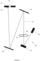
- Figures 5A and 5B show cross-sectional schematic views of components of the picture generating unit 400 of Figure 4 .
- the laser 402 and spatial modulator 404 are not included in Figures 5A and 5B , but each of the Fourier lens 406, first planar turn mirror 408, second planar turn mirror 408 and diffuser 410 comprising target 412 are shown in Figures 5A and 5B.
- Figures 5A and 5B further show the optical axis 502 of the Fourier lens 406.
- the optical axis 502 is substantially parallel to the first portion 416 of the propagation axis 414 which passes through the Fourier lens 406.
- Figures 5A and 5B show a cross-sectional view in the x-z plane (with respect to the coordinates shown in these Figures).
- the change in offset between the Fourier lens 406 and the propagation axis 414 shown in Figure 5A relative to Figure 5B is achieved as a result of relative movement between the propagation axis 414 and the Fourier lens 406 in the x direction.
- This causes beam steering in the x direction at the diffuser (in the embodiment shown in Figures 5A and 5B ).
- beam steering in the y direction can be achieved by changing the offset in the y direction.
- Figure 6 shows the picture generating unit 400 of Figure 4 after calibration.
- the optical axis of the Fourier lens 406 is offset with respect to the first portion 416 of the propagation axis 414 such that the pointing error is compensated for and the second portion of the propagation axis 414 is incident on the diffuser 410 at the centre of the target 412.
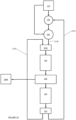
- Figure 7 shows a flow chart representing a method of calibrating a picture generating unit in accordance with the invention.
- Step 702 of the method comprises using the laser 402 to propagate light along the propagation axis 414.
- This step further comprises displaying a hologram of a picture on the spatial light modulator 404, and may optionally comprise calculating the hologram using a hologram engine.
- the light propagated in step 702 illuminates the spatial light modulator 404 so as to spatially modulate the light.
- a first portion 416 of the propagation axis passes through the Fourier lens 406.
- the propagation axis 414 connects / passes through the Fourier lens 406, the two mirrors 408, 409 and is incident on the diffuser 410.
- there may be a pointing error such that the propagation axis 414 is not incident on the centre of the target 412 (as shown in Figure 4 ).
- Step 704 of the method comprises measuring the pointing error between the second portion of the propagation axis 414 and the target 412.
- step 704 comprises measuring a DC spot of the light at or downstream of the diffuser.
- the picture generating unit may comprise a means (such as a block or mask) for separating / removing the DC spot but the DC spot may only be completely removed if picture generating unit 400 is correctly aligned / calibrated.
- a pointing error may be determined. For example, a larger pointing error may be determined the greater the intensity or size of the DC spot.
- Step 706 of the method comprises changing the position of the first portion of the propagation axis 414 with respect to the optical axis 502 of the Fourier lens 406.
- the Fourier lens 406 may be moved while the first portion of the propagation axis 414 is maintained in a constant position to achieve the relative change in position of the two features.
- the Fourier lens 406 is moveable within a first plane defined by the x-y plane (as shown in Figures 5A and 5B ).
- the Fourier lens 406 is moved in the x-y plane in either or both of the x and y direction so as to reduce / minimize the pointing error.
- steps 704 and 706 are repeated a plurality of times.
- the pointing error may be continuously measured and the relative position of the first portion of the propagation axis 414 with respect to the optical axis 502 of the Fourier lens 406 may subsequently adjusted to reduce the pointing error until a threshold (maximum) pointing error is reached such that the pointing error is acceptably low (if not eliminated).
- the method may be iterative.
- the picture generating unit 400 may comprise a controller.
- the controller may be receive measurements / signals from a detector arranged to measure light propagating along the propagation axis 414.
- the detector may be measured to measure the presence (or absence) of a DC spot to infer the pointing error.
- the controller may be arranged to control a movement assembly configured to move the Fourier lens.
- the controller may be arranged to determine / calculate a positional change of the Fourier lens 406 in response to the detected pointing error.
- steps 704 and / or 706 are performed manually.
- a user may adjust / move the Fourier lens 406 in order to reduce or minimize a DC spot.
- these steps may be computer implemented.
- Embodiments refer to an electrically-activated LCOS spatial light modulator by way of example only.
- the teachings of the present disclosure may equally be implemented on any spatial light modulator capable of displaying a computer-generated hologram in accordance with the present disclosure such as any electrically-activated SLMs, optically-activated SLM, digital micromirror device or microelectromechanical device, for example.
- the light source is a laser such as a laser diode.
- the detector is a photodetector such as a photodiode.
- the light receiving surface is a diffuser surface or screen such as a diffuser.
- the holographic projection system of the present disclosure may be used to provide an improved head-up display (HUD) or head-mounted display.
- a vehicle comprising the holographic projection system installed in the vehicle to provide a HUD.
- the vehicle may be an automotive vehicle such as a car, truck, van, lorry, motorcycle, train, airplane, boat, or ship.
- the quality of the holographic reconstruction may be affect by the so-called zero order problem which is a consequence of the diffractive nature of using a pixelated spatial light modulator.
- Such zero-order light can be regarded as "noise" and includes for example specularly reflected light, and other unwanted light from the SLM.
- this "noise" is focussed at the focal point of the Fourier lens leading to a bright spot at the centre of the holographic reconstruction.
- the zero order light may be simply blocked out however this would mean replacing the bright spot with a dark spot.
- Some embodiments include an angularly selective filter to remove only the collimated rays of the zero order.
- Embodiments also include the method of managing the zero-order described in European patent 2,030,072 , which is hereby incorporated in its entirety by reference.
- the size (number of pixels in each direction) of the hologram is equal to the size of the spatial light modulator so that the hologram fills the spatial light modulator. That is, the hologram uses all the pixels of the spatial light modulator. In other embodiments, the hologram is smaller than the spatial light modulator. More specifically, the number of hologram pixels is less than the number of light-modulating pixels available on the spatial light modulator. In some of these other embodiments, part of the hologram (that is, a continuous subset of the pixels of the hologram) is repeated in the unused pixels.
- the technique of "tiling” may be referred to as "tiling" wherein the surface area of the spatial light modulator is divided up into a number of "tiles", each of which represents at least a subset of the hologram. Each tile is therefore of a smaller size than the spatial light modulator.
- the technique of "tiling” is implemented to increase image quality. Specifically, some embodiments implement the technique of tiling to minimise the size of the image pixels whilst maximising the amount of signal content going into the holographic reconstruction.
- the holographic pattern written to the spatial light modulator comprises at least one whole tile (that is, the complete hologram) and at least one fraction of a tile (that is, a continuous subset of pixels of the hologram).
- system comprises physical blocks, such as baffles, arranged to restrict the propagation of the higher order replay fields through the system.
- the method of SSC uses three spatially-separated arrays of light-modulating pixels for the three single-colour holograms.
- An advantage of the SSC method is that the image can be very bright because all three holographic reconstructions may be formed at the same time.
- the three spatially-separated arrays of light-modulating pixels are provided on a common SLM, the quality of each single-colour image is sub-optimal because only a subset of the available light-modulating pixels is used for each colour. Accordingly, a relatively low-resolution colour image is provided.
- the method of FSC can use all pixels of a common spatial light modulator to display the three single-colour holograms in sequence.
- the single-colour reconstructions are cycled (e.g. red, green, blue, red, green, blue, etc.) fast enough such that a human viewer perceives a polychromatic image from integration of the three single-colour images.
- An advantage of FSC is that the whole SLM is used for each colour. This means that the quality of the three colour images produced is optimal because all pixels of the SLM are used for each of the colour images.
- a disadvantage of the FSC method is that the brightness of the composite colour image is lower than with the SSC method - by a factor of about 3 - because each single-colour illumination event can only occur for one third of the frame time. This drawback could potentially be addressed by overdriving the lasers, or by using more powerful lasers, but this requires more power resulting in higher costs and an increase in the size of the system.
- the skilled person will be aware of techniques for converting infrared and ultraviolet light into visible light for the purpose of providing the information to a user.
- the present disclosure extends to using phosphors and/or quantum dot technology for this purpose.
- the holographic reconstruction is a 3D holographic reconstruction. That is, in some embodiments, each computer-generated hologram forms a 3D holographic reconstruction.
- the methods and processes described herein may be embodied on a computer-readable medium.
- the term "computer-readable medium” includes a medium arranged to store data temporarily or permanently such as random-access memory (RAM), read-only memory (ROM), buffer memory, flash memory, and cache memory.
- RAM random-access memory
- ROM read-only memory
- buffer memory buffer memory
- flash memory flash memory
- cache memory cache memory
- computer-readable medium shall also be taken to include any medium, or combination of multiple media, that is capable of storing instructions for execution by a machine such that the instructions, when executed by one or more processors, cause the machine to perform any one or more of the methodologies described herein, in whole or in part.
- computer-readable medium also encompasses cloud-based storage systems.
- computer-readable medium includes, but is not limited to, one or more tangible and non-transitory data repositories (e.g., data volumes) in the example form of a solid-state memory chip, an optical disc, a magnetic disc, or any suitable combination thereof.
- the instructions for execution may be communicated by a carrier medium. Examples of such a carrier medium include a transient medium (e.g., a propagating signal that communicates instructions).
Landscapes
- Physics & Mathematics (AREA)
- General Physics & Mathematics (AREA)
- Optics & Photonics (AREA)
- Engineering & Computer Science (AREA)
- Health & Medical Sciences (AREA)
- Biomedical Technology (AREA)
- General Health & Medical Sciences (AREA)
- Multimedia (AREA)
- Signal Processing (AREA)
- Holo Graphy (AREA)
- Mechanical Light Control Or Optical Switches (AREA)
- Optical Modulation, Optical Deflection, Nonlinear Optics, Optical Demodulation, Optical Logic Elements (AREA)
Applications Claiming Priority (1)
| Application Number | Priority Date | Filing Date | Title |
|---|---|---|---|
| GB2300194.4A GB2626018A (en) | 2023-01-06 | 2023-01-06 | Calibration of a picture generating unit |
Publications (1)
| Publication Number | Publication Date |
|---|---|
| EP4398043A1 true EP4398043A1 (de) | 2024-07-10 |
Family
ID=89121696
Family Applications (1)
| Application Number | Title | Priority Date | Filing Date |
|---|---|---|---|
| EP23214514.4A Pending EP4398043A1 (de) | 2023-01-06 | 2023-12-06 | Kalibrierung einer bilderzeugungseinheit |
Country Status (5)
| Country | Link |
|---|---|
| US (1) | US20240231090A1 (de) |
| EP (1) | EP4398043A1 (de) |
| KR (1) | KR20240110486A (de) |
| CN (1) | CN118311845A (de) |
| GB (1) | GB2626018A (de) |
Citations (6)
| Publication number | Priority date | Publication date | Assignee | Title |
|---|---|---|---|---|
| EP2030072A1 (de) | 2006-05-11 | 2009-03-04 | Cambridge Enterprise Limited | Verfahren zur bildung eines bildes und bildprojektionseinrichtung |
| GB2466023A (en) * | 2008-12-08 | 2010-06-09 | Light Blue Optics Ltd | Holographic Image Projection Systems |
| GB2498170A (en) | 2011-10-26 | 2013-07-10 | Two Trees Photonics Ltd | Fourier domain phase retrieval for 2D image frames |
| GB2501112A (en) | 2012-04-12 | 2013-10-16 | Two Trees Photonics Ltd | Retrieving phase information for holographic image projection |
| US20180120768A1 (en) * | 2016-03-03 | 2018-05-03 | Dualitas Ltd. | Display System |
| US20210041834A1 (en) * | 2019-08-05 | 2021-02-11 | Dualitas Ltd | Holographic Projector |
Family Cites Families (3)
| Publication number | Priority date | Publication date | Assignee | Title |
|---|---|---|---|---|
| JP3944501B2 (ja) * | 2004-09-29 | 2007-07-11 | 株式会社東芝 | ホログラム記録再生装置およびホログラム記録再生方法 |
| HU0700131D0 (en) * | 2007-02-06 | 2007-05-02 | Bayer Innovation Gmbh | Method of reading a fourier a hologram recorder on a holographic storage medium and a holographic storage system |
| CN115497516A (zh) * | 2021-06-17 | 2022-12-20 | 广东紫晶信息存储技术股份有限公司 | 一种全息存储光路系统及其光束校准方法 |
-
2023
- 2023-01-06 GB GB2300194.4A patent/GB2626018A/en active Pending
- 2023-12-06 EP EP23214514.4A patent/EP4398043A1/de active Pending
- 2023-12-13 KR KR1020230180279A patent/KR20240110486A/ko active Pending
- 2023-12-27 US US18/397,818 patent/US20240231090A1/en active Pending
- 2023-12-29 CN CN202311851821.1A patent/CN118311845A/zh active Pending
Patent Citations (6)
| Publication number | Priority date | Publication date | Assignee | Title |
|---|---|---|---|---|
| EP2030072A1 (de) | 2006-05-11 | 2009-03-04 | Cambridge Enterprise Limited | Verfahren zur bildung eines bildes und bildprojektionseinrichtung |
| GB2466023A (en) * | 2008-12-08 | 2010-06-09 | Light Blue Optics Ltd | Holographic Image Projection Systems |
| GB2498170A (en) | 2011-10-26 | 2013-07-10 | Two Trees Photonics Ltd | Fourier domain phase retrieval for 2D image frames |
| GB2501112A (en) | 2012-04-12 | 2013-10-16 | Two Trees Photonics Ltd | Retrieving phase information for holographic image projection |
| US20180120768A1 (en) * | 2016-03-03 | 2018-05-03 | Dualitas Ltd. | Display System |
| US20210041834A1 (en) * | 2019-08-05 | 2021-02-11 | Dualitas Ltd | Holographic Projector |
Also Published As
| Publication number | Publication date |
|---|---|
| GB2626018A (en) | 2024-07-10 |
| US20240231090A1 (en) | 2024-07-11 |
| KR20240110486A (ko) | 2024-07-15 |
| CN118311845A (zh) | 2024-07-09 |
Similar Documents
| Publication | Publication Date | Title |
|---|---|---|
| US12443038B2 (en) | Pupil expander | |
| US12135424B2 (en) | Pupil expansion | |
| EP4083716B1 (de) | Head-up-anzeige | |
| US12443139B2 (en) | Method for a holographic projector | |
| KR102481541B1 (ko) | 홀로그램 프로젝터 | |
| US20250172805A1 (en) | Display device and system | |
| US11681257B2 (en) | Projection | |
| US11829106B2 (en) | Conjugate suppression | |
| US11940759B2 (en) | Holographic projector | |
| EP4369077B1 (de) | Erweiterte augenbox | |
| EP4398043A1 (de) | Kalibrierung einer bilderzeugungseinheit | |
| KR102861907B1 (ko) | 홀로그래픽 프로젝터를 캘리브레이팅하는 방법 |
Legal Events
| Date | Code | Title | Description |
|---|---|---|---|
| PUAI | Public reference made under article 153(3) epc to a published international application that has entered the european phase |
Free format text: ORIGINAL CODE: 0009012 |
|
| STAA | Information on the status of an ep patent application or granted ep patent |
Free format text: STATUS: REQUEST FOR EXAMINATION WAS MADE |
|
| 17P | Request for examination filed |
Effective date: 20231206 |
|
| AK | Designated contracting states |
Kind code of ref document: A1 Designated state(s): AL AT BE BG CH CY CZ DE DK EE ES FI FR GB GR HR HU IE IS IT LI LT LU LV MC ME MK MT NL NO PL PT RO RS SE SI SK SM TR |
|
| P01 | Opt-out of the competence of the unified patent court (upc) registered |
Free format text: CASE NUMBER: APP_14530/2025 Effective date: 20250325 |
|
| GRAP | Despatch of communication of intention to grant a patent |
Free format text: ORIGINAL CODE: EPIDOSNIGR1 |
|
| STAA | Information on the status of an ep patent application or granted ep patent |
Free format text: STATUS: GRANT OF PATENT IS INTENDED |
|
| INTG | Intention to grant announced |
Effective date: 20260128 |
|
| RIN1 | Information on inventor provided before grant (corrected) |
Inventor name: COLE, ALEXANDER |