EP4398067A1 - Elektronische vorrichtung mit lautsprecher - Google Patents
Elektronische vorrichtung mit lautsprecher Download PDFInfo
- Publication number
- EP4398067A1 EP4398067A1 EP22895920.1A EP22895920A EP4398067A1 EP 4398067 A1 EP4398067 A1 EP 4398067A1 EP 22895920 A EP22895920 A EP 22895920A EP 4398067 A1 EP4398067 A1 EP 4398067A1
- Authority
- EP
- European Patent Office
- Prior art keywords
- speaker
- electronic device
- disclosure
- guide
- housing
- Prior art date
- Legal status (The legal status is an assumption and is not a legal conclusion. Google has not performed a legal analysis and makes no representation as to the accuracy of the status listed.)
- Pending
Links
Images


Classifications
-
- G—PHYSICS
- G06—COMPUTING OR CALCULATING; COUNTING
- G06F—ELECTRIC DIGITAL DATA PROCESSING
- G06F1/00—Details not covered by groups G06F3/00 - G06F13/00 and G06F21/00
- G06F1/16—Constructional details or arrangements
-
- H—ELECTRICITY
- H04—ELECTRIC COMMUNICATION TECHNIQUE
- H04B—TRANSMISSION
- H04B1/00—Details of transmission systems, not covered by a single one of groups H04B3/00 - H04B13/00; Details of transmission systems not characterised by the medium used for transmission
- H04B1/06—Receivers
- H04B1/08—Constructional details, e.g. cabinet
-
- H—ELECTRICITY
- H04—ELECTRIC COMMUNICATION TECHNIQUE
- H04R—LOUDSPEAKERS, MICROPHONES, GRAMOPHONE PICK-UPS OR LIKE ACOUSTIC ELECTROMECHANICAL TRANSDUCERS; ELECTRIC HEARING AIDS; PUBLIC ADDRESS SYSTEMS
- H04R1/00—Details of transducers, loudspeakers or microphones
- H04R1/02—Casings; Cabinets ; Supports therefor; Mountings therein
- H04R1/021—Casings; Cabinets ; Supports therefor; Mountings therein incorporating only one transducer
-
- H—ELECTRICITY
- H04—ELECTRIC COMMUNICATION TECHNIQUE
- H04R—LOUDSPEAKERS, MICROPHONES, GRAMOPHONE PICK-UPS OR LIKE ACOUSTIC ELECTROMECHANICAL TRANSDUCERS; ELECTRIC HEARING AIDS; PUBLIC ADDRESS SYSTEMS
- H04R1/00—Details of transducers, loudspeakers or microphones
- H04R1/02—Casings; Cabinets ; Supports therefor; Mountings therein
- H04R1/025—Arrangements for fixing loudspeaker transducers, e.g. in a box, furniture
-
- H—ELECTRICITY
- H04—ELECTRIC COMMUNICATION TECHNIQUE
- H04R—LOUDSPEAKERS, MICROPHONES, GRAMOPHONE PICK-UPS OR LIKE ACOUSTIC ELECTROMECHANICAL TRANSDUCERS; ELECTRIC HEARING AIDS; PUBLIC ADDRESS SYSTEMS
- H04R1/00—Details of transducers, loudspeakers or microphones
- H04R1/20—Arrangements for obtaining desired frequency or directional characteristics
- H04R1/22—Arrangements for obtaining desired frequency or directional characteristics for obtaining desired frequency characteristic only
- H04R1/28—Transducer mountings or enclosures modified by provision of mechanical or acoustic impedances, e.g. resonator, damping means
- H04R1/2869—Reduction of undesired resonances, i.e. standing waves within enclosure, or of undesired vibrations, i.e. of the enclosure itself
- H04R1/2876—Reduction of undesired resonances, i.e. standing waves within enclosure, or of undesired vibrations, i.e. of the enclosure itself by means of damping material, e.g. as cladding
- H04R1/288—Reduction of undesired resonances, i.e. standing waves within enclosure, or of undesired vibrations, i.e. of the enclosure itself by means of damping material, e.g. as cladding for loudspeaker transducers
-
- H—ELECTRICITY
- H05—ELECTRIC TECHNIQUES NOT OTHERWISE PROVIDED FOR
- H05K—PRINTED CIRCUITS; CASINGS OR CONSTRUCTIONAL DETAILS OF ELECTRIC APPARATUS; MANUFACTURE OF ASSEMBLAGES OF ELECTRICAL COMPONENTS
- H05K5/00—Casings, cabinets or drawers for electric apparatus
- H05K5/04—Metal casings
-
- H—ELECTRICITY
- H04—ELECTRIC COMMUNICATION TECHNIQUE
- H04R—LOUDSPEAKERS, MICROPHONES, GRAMOPHONE PICK-UPS OR LIKE ACOUSTIC ELECTROMECHANICAL TRANSDUCERS; ELECTRIC HEARING AIDS; PUBLIC ADDRESS SYSTEMS
- H04R2499/00—Aspects covered by H04R or H04S not otherwise provided for in their subgroups
- H04R2499/10—General applications
- H04R2499/11—Transducers incorporated or for use in hand-held devices, e.g. mobile phones, PDA's, camera's
Definitions
- a speaker that converts electrical energy into mechanical energy and/or acoustic energy may reproduce sound in a manner that generates a longitudinal wave of air through a vertical movement of a diaphragm.
- the front and rear surfaces of the diaphragm generate sounds having phases opposite to each other.
- the front and rear spaces of the diaphragm may have to be separated from each other to prevent destructive interference of the sounds generated from the front and rear surfaces.
- the rear space of the diaphragm may be designed in a closed structure.
- speaker mounting portions provided inside electronic devices are also being miniaturized. There may be a need to have sufficient space at the rear of the diaphragm within a limited space.
- a space in which the rearwardly transmitted sound is generated may be designed in a closed structure, referring to a diaphragm of the speaker of a small electronic device.
- the size of a housing enclosing the speaker as well as the size of the speaker may need to be considered to design a space of a dynamic speaker for rearwardly transmitted sound in a closed structure.
- the size of the housing accommodating the speaker may also need to be reduced enough that the housing may be inserted into the small electronic device.
- the housing accommodating the speaker is made of an injected object with a high degree of freedom in shape implementation.
- the injected object may need to be thick enough that it may be molded, and accordingly, the size of the housing may need to be increased to match the thickness of the housing.
- the housing of the speaker may be made of a metallic stainless-steel material.
- using such material may make it difficult to implement a relatively complex shape, may be disadvantageous as far as space optimization, or may limit the extent to which the size of the exterior may be reduced. Since the movement of the diaphragm of a speaker is limited, when the rear space is limited in size, low frequency band performance may be limited. There may be a desire to use a closed housing structure with a large internal space to improve the sound of the speaker.
- Removing the protective plate and directly attaching the housing to the speaker e may also be an option, but using this technique may not allow sufficient space between the housing and the diaphragm of the speaker for the diaphragm to vibrate.
- a mesh may not be readily attached to the housing.
- an electronic device including a speaker includes a main housing.
- the electronic device may include a cover housing connected to the main housing.
- the electronic device may include a speaker provided inside the main housing and the cover housing.
- the electronic device may include a guide including a guide base seated on the main housing to support the speaker and a guide body extending from the guide base in a first direction and overlapping the speaker in a second direction perpendicular to the first direction.
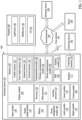
- the memory 130 may store various pieces of data used by at least one component (e.g., the processor 120 or the sensor module 176) of the electronic device 101.
- the various pieces of data may include, for example, software (e.g., the program 140) and input data or output data for a command related thereto.
- the memory 130 may include the volatile memory 132 or the non-volatile memory 134.
- the program 140 may be stored as software in the memory 130, and may include, for example, an operating system (OS) 142, middleware 144, or an application 146.
- OS operating system
- middleware middleware
- application application
- the audio module 170 may convert sound into an electric signal or vice versa. According to an example embodiment of the disclosure, the audio module 170 may obtain the sound via the input module 150 or output the sound via the sound output module 155 or an external electronic device (e.g., an external electronic device 102, such as a speaker or headphones) directly or wirelessly connected to the electronic device 101.
- an external electronic device e.g., an external electronic device 102, such as a speaker or headphones
- the sensor module 176 may detect an operational state (e.g., power or temperature) of the electronic device 101 or an environmental state (e.g., a state of a user) external to the electronic device 101, and generate an electric signal or data value corresponding to the detected state.
- the sensor module 176 may include, for example, a gesture sensor, a gyro sensor, an atmospheric pressure sensor, a magnetic sensor, an acceleration sensor, a grip sensor, a proximity sensor, a color sensor, an infrared (IR) sensor, a biometric sensor, a temperature sensor, a humidity sensor, or an illuminance sensor.
- the communication module 190 may support establishing a direct (e.g., by wire) communication channel or a wireless communication channel between the electronic device 101 and the external electronic device (e.g., the external electronic device 102, the external electronic device 104, or the server 108) and performing communication via the established communication channel.
- the communication module 190 may include one or more of CPs that are operable independently from the processor 120 (e.g., an AP) and that support direct (e.g., by wire) communication or wireless communication.
- the communication module 190 may include a wireless communication module 192 (e.g., a cellular communication module, a short-range wireless communication module, or a global navigation satellite system (GNSS) communication module) or a wired communication module 194 (e.g., a local area network (LAN) communication module, or a power line communication (PLC) module).
- a wireless communication module 192 e.g., a cellular communication module, a short-range wireless communication module, or a global navigation satellite system (GNSS) communication module
- GNSS global navigation satellite system
- wired communication module 194 e.g., a local area network (LAN) communication module, or a power line communication (PLC) module.
- LAN local area network
- PLC power line communication
- a corresponding one of these communication modules may communicate with the external electronic device 104 via the first network 198 (e.g., a short-range communication network, such as Bluetooth TM , wireless-fidelity (Wi-Fi) direct, or infrared data association (IrDA)) or the second network 199 (e.g., a long-range communication network, such as a legacy cellular network, a fifth generation (5G) network, a next-generation communication network, the Internet, or a computer network (e.g., a LAN or a wide area network (WAN)).
- the wireless communication module 192 may identify and authenticate the electronic device 101 in a communication network, such as the first network 198 or the second network 199, using subscriber information (e.g., international mobile subscriber identity (IMSI)) stored in the SIM 196.
- subscriber information e.g., international mobile subscriber identity (IMSI)
- the wireless communication module 192 may support a 5G network after a fourth generation (4G) network, and next-generation communication technology, e.g., new radio (NR) access technology.
- the NR access technology may support enhanced mobile broadband (eMBB), massive machine type communications (mMTC), or ultra-reliable and low-latency communications (URLLC).
- eMBB enhanced mobile broadband
- mMTC massive machine type communications
- URLLC ultra-reliable and low-latency communications
- the wireless communication module 192 may support a high-frequency band (e.g., a millimeter wave (mmWave) band) to achieve, e.g., a high data transmission rate.
- mmWave millimeter wave
- the wireless communication module 192 may support various technologies for securing performance on a high-frequency band, such as, e.g., beamforming, massive multiple-input and multiple-output (MIMO), full dimensional MIMO (FD-MIMO), an array antenna, analog beamforming, or a large-scale antenna.
- the wireless communication module 192 may support various requirements specified in the electronic device 101, an external electronic device (e.g., the external electronic device 104), or a network system (e.g., the second network 199).
- the wireless communication module 192 may support a peak data rate (e.g., 20 Gbps or more) for implementing eMBB, loss coverage (e.g., 164 dB or less) for implementing mMTC, or U-plane latency (e.g., 0.5 ms or less for each of downlink (DL) and uplink (UL), or a round trip of 1 ms or less) for implementing URLLC.
- a peak data rate e.g., 20 Gbps or more
- loss coverage e.g., 164 dB or less
- U-plane latency e.g., 0.5 ms or less for each of downlink (DL) and uplink (UL), or a round trip of 1 ms or less
- the antenna module 197 may transmit or receive a signal or power to or from the outside (e.g., the external electronic device) of the electronic device 101.
- the antenna module 197 may include an antenna including a radiating element including a conductive material or a conductive pattern formed in or on a substrate (e.g., a printed circuit board (PCB)).
- the antenna module 197 may include a plurality of antennas (e.g., array antennas). In such a case, at least one antenna appropriate for a communication scheme used in a communication network, such as the first network 198 or the second network 199, may be selected by, for example, the communication module 190 from the plurality of antennas.
- the signal or power may be transmitted or received between the communication module 190 and the external electronic device via the at least one selected antenna.
- another component e.g., a radio frequency integrated circuit (RFIC)
- RFIC radio frequency integrated circuit
- the antenna module 197 may form a mmWave antenna module.
- the mmWave antenna module may include a PCB, an RFIC disposed on a first surface (e.g., a bottom surface) of the PCB or adjacent to the first surface and capable of supporting a designated a high-frequency band (e.g., the mmWave band), and a plurality of antennas (e.g., array antennas) disposed on a second surface (e.g., a top or a side surface) of the PCB, or adjacent to the second surface and capable of transmitting or receiving signals in the designated high-frequency band.
- a PCB e.g., an RFIC disposed on a first surface (e.g., a bottom surface) of the PCB or adjacent to the first surface and capable of supporting a designated a high-frequency band (e.g., the mmWave band)
- a plurality of antennas e.g., array antennas
- At least some of the above-described components may be coupled mutually and communicate signals (e.g., commands or data) therebetween via an inter-peripheral communication scheme (e.g., a bus, general purpose input and output (GPIO), serial peripheral interface (SPI), or mobile industry processor interface (MIPI)).
- an inter-peripheral communication scheme e.g., a bus, general purpose input and output (GPIO), serial peripheral interface (SPI), or mobile industry processor interface (MIPI)
- commands or data may be transmitted or received between the electronic device 101 and the external electronic device 104 via the server 108 coupled with the second network 199.
- Each of the external electronic devices 102 or 104 may be a device of the same type as or a different type than the electronic device 101.
- all or some of operations to be executed by the electronic device 101 may be executed by one or more of the external electronic devices 102, 104, and 108.
- the electronic device 101 may request one or more of external electronic devices to perform at least part of the function or service.
- the one or more of external electronic devices receiving the request may perform the at least part of the function or service, or an additional function or an additional service related to the request, and may transfer an outcome of the performing to the electronic device 101.
- the electronic device 101 may provide the result, with or without further processing of the result, as at least part of a response to the request.
- cloud computing distributed computing, mobile edge computing (MEC), or client-server computing technology may be used, for example.
- the electronic device 101 may provide ultra low-latency services using, e.g., distributed computing or mobile edge computing.
- the external electronic device 104 may include an Internet-of things (IoT) device.
- the server 108 may be an intelligent server using machine learning and/or a neural network.
- the external electronic device 104 or the server 108 may be included in the second network 199.
- the electronic device 101 may be applied to intelligent services (e.g., smart home, smart city, smart car, or healthcare) based on 5G communication technology or IoT-related technology.
- the electronic device may be one of various types of electronic devices.
- the electronic device may include, for example, a portable communication device (e.g., a smartphone), a computer device, a portable multimedia device, a portable medical device, a camera, a wearable device, or a home appliance device.
- a portable communication device e.g., a smartphone
- a computer device e.g., a laptop, a desktop, a tablet, or a portable multimedia device.
- a portable medical device e.g., a portable medical device
- camera e.g., a portable medical device
- a camera e.g., a camera
- a wearable device e.g., a portable medical device
- a home appliance device e.g., a portable medical device, a portable medical device, a camera, a wearable device, or a home appliance device.
- the electronic device is not limited to those described above.
- module may include a unit implemented in hardware, software, or firmware, and may interchangeably be used with other terms, for example, “logic,” “logic block,” “part,” or “circuitry”.
- a module may be a single integral component, or a minimum unit or part thereof, adapted to perform one or more of functions.
- the module may be implemented in a form of an application-specific integrated circuit (ASIC).
- ASIC application-specific integrated circuit
- Various example embodiments as set forth herein may be implemented as software (e.g., the program 140) including one or more of instructions that are stored in a storage medium (e.g., an internal memory 136 or an external memory 138) that is readable by a machine (e.g., the electronic device 101).
- a processor e.g., the processor 120
- the one or more of instructions may include a code generated by a complier or a code executable by an interpreter.
- the machine-readable storage medium may be provided in the form of a non-transitory storage medium.
- non-transitory simply means that the storage medium is a tangible device, and does not include a signal (e.g., an electromagnetic wave), but this term does not differentiate between where data is semi-permanently stored in the storage medium and where the data is temporarily stored in the storage medium.
- a method may be included and provided in a computer program product.
- the computer program product may be traded as a product between a seller and a buyer.
- the computer program product may be distributed in the form of a machine-readable storage medium (e.g., a compact disc read only memory (CD-ROM)), or be distributed (e.g., downloaded or uploaded) online via an application store (e.g., PlayStore TM ), or between two user devices (e.g., smart phones) directly. If distributed online, at least part of the computer program product may be temporarily generated or at least temporarily stored in the machine-readable storage medium, such as memory of the manufacturer's server, a server of the application store, or a relay server.
- a machine-readable storage medium e.g., a compact disc read only memory (CD-ROM)
- an application store e.g., PlayStore TM
- two user devices e.g., smart phones
- each component e.g., a module or a program of the above-described components may include a single entity or multiple entities, and some of the multiple entities may be separately disposed in different components. According to various embodiments of the disclosure, one or more of the above-described components may be omitted, or one or more of other components may be added. Alternatively or additionally, a plurality of components (e.g., modules or programs) may be integrated into a single component. In such a case, according to various embodiments of the disclosure, the integrated component may still perform one or more of functions of each of the plurality of components in the same or similar manner as they are performed by a corresponding one of the plurality of components before the integration.
- the integrated component may still perform one or more of functions of each of the plurality of components in the same or similar manner as they are performed by a corresponding one of the plurality of components before the integration.
- operations performed by the module, the program, or another component may be carried out sequentially, in parallel, repeatedly, or heuristically, or one or more of the operations may be executed in a different order or omitted, or one or more other operations may be added.
- FIG. 2A is a perspective view of a front surface of a mobile electronic device according to an embodiment of the disclosure
- FIG. 2B is a perspective view of a rear surface of the electronic device of FIG. 2A according to an embodiment of the disclosure.
- an electronic device 200 may include a housing 210 including a first surface (or a front surface) 210A, a second surface (or a rear surface) 210B, and a side surface 210C surrounding a space between the first surface 210A and the second surface 210B.
- the housing may also be a structure which forms a portion of the first surface 210A, the second surface 210B, and the side surface 210C of FIGS. 2A and 2B .
- the first surface 210A may be formed of a front plate 202 (e.g., a polymer plate or a glass plate including various coating layers) of which at least a portion is substantially transparent.
- the second surface 210B may be formed of a back plate 211 that is substantially opaque.
- the back plate 211 may be formed of coated or colored glass, ceramic, polymer, metal materials (e.g., aluminum, stainless steel (SS), or magnesium) or a combination of at least two of the above materials.
- the side surface 210C may be coupled to the front plate 202 and the back plate 211 and may be formed by a side plate (or a "side member") 218 including metal and/or polymer.
- the back plate 211 and the side plate 218 may be integrally formed and may include the same material (e.g., a metal material, such as aluminum).
- the front plate 202 may include two first areas 210D that are curved and extend seamlessly from the first surface 210A toward the back plate 211, at both ends of a long edge of the front plate 202.
- the back plate 211 may include two second areas 210E that are curved and extend seamlessly from the second surface 210B toward the front plate 202, at both ends of a long edge thereof.
- the front plate 202 (or the back plate 211) may include only one of the first areas 210D (or the second areas 210E). In another embodiment of the disclosure, some of the first areas 210D or the second areas 210E may not be included.
- the side plate 218 when viewed from a side surface of the electronic device 200, may have a first thickness (or width) in a direction of a side surface not including the first areas 210D or the second areas 210E, and have a second thickness less than the first thickness in a direction of a side surface including the first areas 210D or the second areas 210E.
- the first areas 210D or the second areas 210E may be formed to be flat instead of being bent, to form a substantially single plane with the first surface 210A or the second surface 210B.
- the electronic device 200 may include at least one of a display 201, audio modules 203, 207, and 214, sensor modules 204, 216, and 219, camera modules 205, 212, and 213, key input devices 217, a light-emitting element 206, and connector holes 208 and 209.
- the electronic device 200 may not include at least one (e.g., the key input devices 217 or the light-emitting element 206) of the components, or may additionally include other components.
- the display 201 may be exposed through a substantial portion of the front plate 202, for example. In some embodiments of the disclosure, at least a portion of the display 201 may be exposed through the front plate 202 that forms the first surface 210A and the first areas 210D of the side surface 210C. In some embodiments of the disclosure, an edge of the display 201 may be formed in a shape substantially the same as the shape of the periphery of the front plate 202 adjacent thereto. In another example embodiment (not shown), in order to enlarge the exposed area of the display 201, a distance between the edge of the display 201 and the periphery of the front plate 202 may be substantially the same.
- a recess or an opening may be formed in a portion of a screen display area of the display 201, and at least one of the audio module 214, the sensor module 204, and the camera module 205, and the light-emitting element 206 that are aligned with the recess, or the opening may be included.
- a rear surface of the screen display area of the display 201 may include at least one of the audio module 214, the sensor module 204, the camera module 205, the sensor module 216 (e.g., a fingerprint sensor), and the light-emitting element 206.
- the display 201 may be coupled to or disposed adjacent to a touch detection circuit, a pressure sensor for measuring an intensity (pressure) of a touch, and/or a digitizer for detecting a magnetic-type stylus pen.
- a touch detection circuit for measuring an intensity (pressure) of a touch
- a digitizer for detecting a magnetic-type stylus pen.
- at least a portion of the sensor modules 204 and 219, and/or at least a portion of the key input device 217 may be disposed in the first areas 210D and/or the second areas 210E.
- the audio modules 203, 207, and 214 may include a plate hole 203, speaker holes 207 and 214, and a microphone (not shown) provided in the housing 210.
- the plate hole 203 may guide sound from the outside to the microphone.
- the speaker holes 207 and 214 may include an external speaker hole 207 and a receiver hole for a call 214.
- the speaker holes 207 and 214 and the plate hole 203 may be implemented as a single hole, or a speaker (e.g., a piezo speaker) may be included without the speaker holes 207 and 214.
- the sensor modules 204, 216, and 219 may generate an electrical signal or a data value corresponding to an internal operating state of the electronic device 200 or an external environmental state.
- the sensor modules 204, 216, and 219 may include, for example, a first sensor module 204 (e.g., a proximity sensor) and/or a second sensor module (not shown) (e.g., a fingerprint sensor) disposed on the first surface 210A of the housing 210, and/or a third sensor module 219 (e.g., a heart rate monitoring (HRM) sensor) and/or a fourth sensor module 216 (e.g., a fingerprint sensor) disposed on the second surface 210B of the housing 210.
- HRM heart rate monitoring
- the fingerprint sensor may be disposed on both the first surface 210A (e.g., the display 201) and the second surface 210B of the housing 210.
- the electronic device 200 may further include at least one of sensor modules (not shown), for example, a gesture sensor, a gyro sensor, an atmospheric pressure sensor, a magnetic sensor, an acceleration sensor, a grip sensor, a color sensor, an infrared (IR) sensor, a biometric sensor, a temperature sensor, a humidity sensor, or an illuminance sensor 204.
- the camera modules 205, 212, and 213 may include a first camera device 205 disposed on the first surface 210A of the electronic device 200, a second camera device 212 disposed on the second surface 210B, and/or a flash 213.
- the camera modules 205 and 212 may each include one or more of lenses, an image sensor, and/or an image signal processor.
- a flash 213 may include, for example, a light-emitting diode (LED) or a xenon lamp.
- two or more lenses e.g., infrared camera, wide-angle, and telephoto lenses
- image sensors may be disposed on one surface of the electronic device 200.
- the key input devices 217 may be disposed on the side surface 210C of the housing 210.
- the electronic device 200 may not include some or any of the key input devices 217 mentioned above, and the key input device 217 that is not included may be implemented in another form, such as a soft key on the display 201.
- the key input devices 217 may include the sensor module 216 disposed on the second surface 210B of the housing 210.
- the light-emitting element 206 may be disposed on, for example, the first surface 210A of the housing 210.
- the light-emitting element 206 may provide, for example, state information of the electronic device 200 in the form of light.
- the light-emitting element 206 may provide, for example, a light source that is linked to the operation of the camera module 205.
- the light-emitting element 206 may include, for example, an LED, an IR LED, and a xenon lamp.
- the connector holes 208 and 209 may include a first connector hole 208 for accommodating a connector (e.g., a universal serial bus (USB) connector) for transmitting and receiving power and/or data to and from an external electronic device, and/or a second connector hole 209 (e.g., an earphone jack) for accommodating a connector for transmitting and receiving an audio signal to and from an external electronic device.
- the electronic device 200 may include an electronic device, such as a bar type, a foldable type, a rollable type, a slidable type, a wearable type, and a tablet personal computer (PC) and/or a notebook PC.
- the electronic device 200 according to an embodiment of the disclosure is not limited to the above-described example, and may include various other electronic devices.
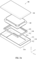
- FIG. 3A is an exploded perspective view of a sound output module according to an embodiment of the disclosure.
- FIG. 3B is an exploded perspective view of a sound output module of FIG. 3A viewed from a different angle according to an embodiment of the disclosure.
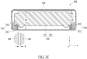
- FIG. 3C is a cross-sectional view of a sound output module according to an embodiment of the disclosure.
- an electronic device may include a sound output module 300 (e.g., the sound output module 155 of FIG. 1 ) including a speaker 340.
- the sound output module 300 may be included not only in an electronic device (e.g., the electronic device 200 of FIG. 2A ) in a form of a terminal, such as a mobile phone, a tablet, or a desktop but also in a sound device using a speaker, such as a headset, television (TV), or a home theater.
- An electronic device in which the sound output module 300 is provided is not limited thereto.
- the sound output module 300 may include a main housing 310, a cover housing 320, a guide 330, and a speaker 340.
- the speaker 340 may include a speaker body 341 and a protective plate 342.
- the speaker body 341 may include a diaphragm, and the protective plate 342 may protect the diaphragm.
- the main housing 310 may expose a portion of the protective plate 342 of the speaker 340.
- the main housing 310 may include an opening formed to penetrate through a central portion thereof and may expose the protective plate 342 through the opening.
- the main housing 310 may include a main base 311 formed in parallel to an xy plane, and a main body 312 expending toward a z-axial direction from the main base 311.
- the z-axial direction may be referred to as a first direction.
- the main housing 310 may include a stainless-steel material.
- the main base 311 may support the guide 330.
- the main base 311 may be provided approximately parallel to a central portion of the protective plate 342.
- the main base 311 may include an inner edge 311a and an outer edge 311b.
- the inner edge 311a and the outer edge 311b may each have a loop shape.
- An inner side of the inner edge 311a may be an opening to expose the protective 342 to the outside.
- the main body 312 may extend from the outer edge 311b of the main base 311.
- the main body 312 may face the guide 330 in a direction parallel to the xy plane, that is, a direction perpendicular to the z-axis.
- the direction parallel to the xy plane or the direction perpendicular to the z-axis may be referred to as a second direction.
- a connecting portion of the main base 311 and the main body 312 may have a curved shape.
- the main base 311 and the main body 312 may support at least two surfaces of the guide 330 to assist the guide 330 to be fixed and not unintentionally movable.
- the main base 311 and the main body 312 may support a bottom surface and an outer side surface of the guide 330.
- the main housing 310 and the cover housing 320 may include a mesh that may reduce or prevent an influx of a foreign material and/or moisture into a diaphragm of the speaker 340.
- the guide base 331 may be disposed in the main base 311.
- the guide base 331 may include a curved portion 331a formed on an outer edge portion.
- the guide base 331 may have a shape of an outer side surface corresponding to a shape of an inner side surface of the main housing 310.
- the guide base 331 may maintain a state in surface contact with the main housing 310.
- the seal 550 may be provided in a state of being compressed between the speaker body 541 and the guide body 532.
- the seal 550 may be attached to an outer circumferential surface of the speaker body 541 in a form of surrounding the speaker body 541.
- the seal 550 may be compressed in a direction perpendicular to a z-axial direction by the guide body 532 in a process in which the speaker body 541 is moving in the z-axial direction to be inserted inside the guide body 532. Air flow may be blocked between a -z side area and +z side area with respect to the seal 550.
- the seal 550 may include a compressive member, such as rubber or sponge, or an adhesive member, such as thermal adhesive tape or glue.
- FIG. 6 is a cross-sectional view and a partially enlarged view of a sound output module according to an embodiment of the disclosure.
- the seal 750 may be provided in a state of being compressed between the protective plate 742 and the guide base 731.
- the seal 750 may be attached to an outer circumferential surface of the protective plate 742 in a form of surrounding the protective plate 742.
- the seal 750 may be compressed in a direction perpendicular to a z-axial direction by the guide base 731 in a process in which the protective plate 742 is moving in the z-axial direction to be inserted inside the guide base 731. Air flow may be blocked between a -z-side area and a +z-side area with respect to the seal 750.
- FIG. 9 is a cross-sectional view of a sound output module according to an embodiment of the disclosure.
- At least a portion of the speaker 940 may be exposed to the outside the main housing 910 and the cover housing 920.
- a surface of the speaker 940 facing a +x direction may be exposed to the outside.
- a sound output module 1000 may include a main housing 1010, a cover housing 1020, a guide 1030, a speaker 1040, a detachable cover 1070, a pocket 1080, and a porous capsule 1090.
- the detachable cover 1070 may be detachably connected to the main housing 1010. Even if the detachable cover 1070 is removed, the sound output module 1000 may keep its shape. A user may maintain internal components of the sound output module 1000 by removing the detachable cover 1070.
- the detachable cover 1070 may also be detachably connected to the cover housing 1020.
- a sound output module 1100 may include a main housing 1110, a cover housing 1120, a guide 1130, and a speaker 1140.
- the main housing 1110 may perform a function of a protective plate (e.g., the protective plate 342 of FIG. 3C ).
- the main housing 1110 may cover a diaphragm (not shown) of the speaker 1140 to protect the diaphragm.
- the main housing 1110 may include a plurality of holes 1110a communicating between an inner space and an outer space of the main housing 1110.
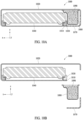
- FIG. 12A is a cross-sectional view of a sound output module according to an embodiment of the disclosure
- FIG. 12B is a cross-sectional view illustrating a sound output module of FIG. 12A viewed from a different angle according to an embodiment of the disclosure.
- the main housing 1210 may be adhered to the protective plate 1242.
- the main housing 1210 may overlap the protective plate 1242 in a direction parallel to an xy plane.
- the speaker body 1241 may include a yoke Y formed on one surface thereof. At least a portion of the speaker body 1241 may be exposed to an outside the cover housing 1220. For example, the yoke Y of the speaker body 1241 may be exposed to the outside in a +z direction through an opening formed in the cover housing 1220.
- a -x-side area of the speaker 1240 may have an area sufficient to generate sound.
- FIG. 13 is a cross-sectional view of a sound output module according to an embodiment of the disclosure.
- a sound output module 1300 may include a main housing 1310, a cover housing 1320, and a speaker 1340.
- the speaker 1340 may include a speaker body 1341 and a protective plate 1342.
- the protective plate 1342 may include a contacting portion connected to the speaker body 1341, a connecting portion extending from the contacting portion in a -z direction, and an exposed portion connected to the connecting portion and exposed to the outside in the -z direction.
- the contacting portion of the protective plate 1342 may be formed to extend outwardly in a direction parallel to an xy plane to be connected to the main housing 1310.
- the contacting portion of the protective plate 1342 may be adhered or welded to the main housing 1310.
- FIG. 14 is a cross-sectional view of a sound output module according to an embodiment of the disclosure.
- a sound output module 1400 may include a main housing 1410, a cover housing 1420, and a speaker 1440.
- the speaker 1440 may include a speaker body 1441 and a protective plate 1442.
- the main housing 1410 may include a main base 1411, a main body 1412 extending from an outer edge of the main base 1411 in a +z direction, a first rib 1413 extending from an inner edge of the main base 1411 in the +z direction, and a second rib 1414 extending from the first rib 1413 in a direction parallel to an xy plane.
- the second rib 1414 may extend in a direction toward the main body 1412.
- FIG. 15 is a cross-sectional view of a sound output module according to an embodiment of the disclosure.
- a sound output module 1500 may include a main housing 1510, a cover housing 1520, and a speaker 1540.
- the speaker 1540 may include a speaker body 1541 and a protective plate 1542.
- the speaker body 1541 may include a speaker head protruding in a -z direction to surround the protective plate 1542.
- the speaker head may be provided in surface contact with the main base 1510.
- an electronic device including a speaker may include a main housing 310, a cover housing 320 connected to the main housing, a speaker 340 provided inside the main housing and the cover housing, and a guide 330 including a guide base 331 seated on the main housing to support the speaker and a guide body 332 extending from the guide base in a first direction and overlapping the speaker in a second direction perpendicular to the first direction.
- the main housing 310 may include a stainless-steel material.
- the guide body 332 may be in contact with the speaker.
- the speaker 340 may include a speaker body 341 of which at least a portion is provided inside the guide body, and a protective plate 342, of which at least a portion is provided inside the guide base, connected to the speaker body.
- the protective plate 342 may be spaced apart from the guide base in the second direction.
- a first distance L1 from a bottom surface of the cover housing to the protective plate may be less than a second distance L2 from the bottom surface of the cover housing to the guide base.
- At least a portion of the main housing 410 may be provided in a state of being inserted into the guide.
- the main housing 410 may include a main base 411 in contact with the guide base in the first direction, and a main body 412 extending from an outer edge of the main base to be in contact with the guide base and the guide body in the second direction.
- the main housing 410 may further include a main rib 413 extending from an inner edge of the main base and inserted into the guide.
- the main body 412 may be spaced apart from the guide in the second direction.
- At least a portion of the speaker 940 may be exposed to an outside the main housing and the cover housing.
- an electronic device including a speaker may include a main housing 1210 including a main base and a main body extending from the main base, a cover housing 1220 connected to the main body, and a speaker 1240 including a speaker body 1241 provided inside the main housing and the cover housing and a protective plate 1242 of which at least a portion is exposed to an outside the main housing, connected to the speaker body.
- At least a portion of the speaker body 1241 may be exposed to an outside the cover housing.
- the main housing 1210 may be attached to the cover housing.
- an electronic device including a speaker may include a main housing 310 including a stainless steel material, a cover housing 320 connected to the main housing and including a stainless steel material, a speaker 340 provided inside the main housing and the cover housing, and a guide 330 including a guide base seated on the main housing to support the speaker and a guide body extending from the guide base in a first direction and overlapping the speaker in a second direction perpendicular to the first direction, wherein the main housing may include a main base in contact with the guide base in the first direction and a main body extending from an outer edge of the main base to be in contact with the guide base and the guide body in the second direction.
Landscapes
- Engineering & Computer Science (AREA)
- Signal Processing (AREA)
- Physics & Mathematics (AREA)
- Acoustics & Sound (AREA)
- Health & Medical Sciences (AREA)
- Otolaryngology (AREA)
- Theoretical Computer Science (AREA)
- Microelectronics & Electronic Packaging (AREA)
- Human Computer Interaction (AREA)
- General Engineering & Computer Science (AREA)
- General Physics & Mathematics (AREA)
- Computer Networks & Wireless Communication (AREA)
- Telephone Set Structure (AREA)
Applications Claiming Priority (3)
| Application Number | Priority Date | Filing Date | Title |
|---|---|---|---|
| KR20210158765 | 2021-11-17 | ||
| KR1020210192966A KR20230072358A (ko) | 2021-11-17 | 2021-12-30 | 스피커를 포함하는 전자 장치 |
| PCT/KR2022/017183 WO2023090713A1 (ko) | 2021-11-17 | 2022-11-04 | 스피커를 포함하는 전자 장치 |
Publications (2)
| Publication Number | Publication Date |
|---|---|
| EP4398067A1 true EP4398067A1 (de) | 2024-07-10 |
| EP4398067A4 EP4398067A4 (de) | 2025-01-08 |
Family
ID=86397377
Family Applications (1)
| Application Number | Title | Priority Date | Filing Date |
|---|---|---|---|
| EP22895920.1A Pending EP4398067A4 (de) | 2021-11-17 | 2022-11-04 | Elektronische vorrichtung mit lautsprecher |
Country Status (3)
| Country | Link |
|---|---|
| US (1) | US12549878B2 (de) |
| EP (1) | EP4398067A4 (de) |
| WO (1) | WO2023090713A1 (de) |
Families Citing this family (1)
| Publication number | Priority date | Publication date | Assignee | Title |
|---|---|---|---|---|
| WO2024212031A1 (zh) * | 2023-04-10 | 2024-10-17 | 瑞声光电科技(常州)有限公司 | 扬声器箱 |
Family Cites Families (15)
| Publication number | Priority date | Publication date | Assignee | Title |
|---|---|---|---|---|
| JP3783343B2 (ja) | 1997-06-20 | 2006-06-07 | 松下電器産業株式会社 | 携帯端末装置 |
| JP4127443B2 (ja) | 1999-03-25 | 2008-07-30 | シチズン電子株式会社 | 多機能型発音体 |
| KR20030012589A (ko) * | 2001-08-02 | 2003-02-12 | 엘지전자 주식회사 | 이동통신 단말기의 음향 유니트 밀봉구조 |
| JP2010119032A (ja) * | 2008-11-14 | 2010-05-27 | Nec Saitama Ltd | スピーカ装置、携帯型電子機器、スピーカ装置の製造方法、及びスピーカ装置の制御方法 |
| JP5471435B2 (ja) | 2009-12-28 | 2014-04-16 | パナソニック株式会社 | スピーカ用振動板及びこれを用いたスピーカと携帯端末装置 |
| KR101111895B1 (ko) * | 2010-01-06 | 2012-02-15 | 주식회사 비에스이 | 다기능 마이크로 스피커 |
| KR101236057B1 (ko) * | 2011-10-12 | 2013-02-21 | 부전전자 주식회사 | 마이크로 스피커모듈 |
| KR101468631B1 (ko) * | 2013-06-14 | 2014-12-05 | 부전전자 주식회사 | 진동변환기와 이를 이용한 디스플레이 윈도우 진동장치 |
| CN206341395U (zh) | 2016-10-26 | 2017-07-18 | 瑞声科技(新加坡)有限公司 | 扬声器箱 |
| US10154329B2 (en) * | 2017-03-21 | 2018-12-11 | Google Llc | Audio output device and audio output port of computing device |
| KR101876804B1 (ko) | 2017-06-22 | 2018-07-10 | 유수진 | 하이브리드 스피커 |
| CN108235198B (zh) * | 2018-02-24 | 2020-02-18 | 歌尔股份有限公司 | 一种扬声器模组及电子设备 |
| CN115152244B (zh) * | 2020-02-21 | 2025-01-03 | 三星电子株式会社 | 扬声器模块和包括该扬声器模块的电子装置 |
| CN212628375U (zh) | 2020-05-29 | 2021-02-26 | 瑞声科技(新加坡)有限公司 | 发声器件 |
| CN213462310U (zh) | 2020-07-08 | 2021-06-15 | 瑞声科技(新加坡)有限公司 | 一种发声装置 |
-
2022
- 2022-11-04 WO PCT/KR2022/017183 patent/WO2023090713A1/ko not_active Ceased
- 2022-11-04 EP EP22895920.1A patent/EP4398067A4/de active Pending
-
2023
- 2023-03-23 US US18/188,810 patent/US12549878B2/en active Active
Also Published As
| Publication number | Publication date |
|---|---|
| US20230232141A1 (en) | 2023-07-20 |
| US12549878B2 (en) | 2026-02-10 |
| EP4398067A4 (de) | 2025-01-08 |
| WO2023090713A1 (ko) | 2023-05-25 |
Similar Documents
| Publication | Publication Date | Title |
|---|---|---|
| US12453058B2 (en) | Heat dissipation structure and electronic device including same | |
| KR20220039535A (ko) | 카메라 모듈의 접점 구조 및 이를 포함하는 전자 장치 | |
| KR102928004B1 (ko) | 커넥터를 포함하는 전자 장치 | |
| US12457453B2 (en) | Electronic device and speaker structure included in electronic device | |
| US20250274645A1 (en) | Electronic device including camera module | |
| US12549878B2 (en) | Electronic device including speaker | |
| US12542993B2 (en) | Electronic device including sound module | |
| US12439189B2 (en) | Electronic device comprising microphone module | |
| US12375845B2 (en) | Audio output device including extended resonance space and electronic device including the same | |
| US20240121539A1 (en) | Electronic device including speaker | |
| CN116250225A (zh) | 相机模块的接触结构和包括其的电子装置 | |
| KR20220158943A (ko) | 차폐 부재를 포함하는 전자 장치 | |
| US20260020206A1 (en) | Board assembly and electronic device including same | |
| US20240155274A1 (en) | Electronic device including insulating structure for speaker | |
| US20260003404A1 (en) | Electronic device including waterproofing structure | |
| RU2838587C1 (ru) | Электронное устройство, содержащее микрофонный модуль | |
| EP4345573B1 (de) | Elektronische vorrichtung mit lautsprecher | |
| US12058484B2 (en) | Electronic device including speaker module | |
| US11962960B2 (en) | Electronic device including sound component assembly | |
| EP4372524A1 (de) | Elektronische vorrichtung mit resonanzraum eines lautsprechers | |
| EP4362436A1 (de) | Elektronische vorrichtung mit struktur zur isolierung der von einem lautsprecher emittierten wärme | |
| CN118355349A (zh) | 包括扬声器的电子装置 | |
| KR20230072358A (ko) | 스피커를 포함하는 전자 장치 | |
| EP4178182A1 (de) | Rückseitenabdeckung und elektronische vorrichtung damit | |
| KR20250021928A (ko) | 카메라를 포함하는 전자 장치 및 그 제조 방법 |
Legal Events
| Date | Code | Title | Description |
|---|---|---|---|
| STAA | Information on the status of an ep patent application or granted ep patent |
Free format text: STATUS: THE INTERNATIONAL PUBLICATION HAS BEEN MADE |
|
| PUAI | Public reference made under article 153(3) epc to a published international application that has entered the european phase |
Free format text: ORIGINAL CODE: 0009012 |
|
| STAA | Information on the status of an ep patent application or granted ep patent |
Free format text: STATUS: REQUEST FOR EXAMINATION WAS MADE |
|
| 17P | Request for examination filed |
Effective date: 20240404 |
|
| AK | Designated contracting states |
Kind code of ref document: A1 Designated state(s): AL AT BE BG CH CY CZ DE DK EE ES FI FR GB GR HR HU IE IS IT LI LT LU LV MC ME MK MT NL NO PL PT RO RS SE SI SK SM TR |
|
| A4 | Supplementary search report drawn up and despatched |
Effective date: 20241206 |
|
| RIC1 | Information provided on ipc code assigned before grant |
Ipc: H04R 1/02 20060101ALI20241202BHEP Ipc: G06F 1/16 20060101AFI20241202BHEP |
|
| DAV | Request for validation of the european patent (deleted) | ||
| DAX | Request for extension of the european patent (deleted) |