EP4398070A2 - Dispositif électronique ayant un système d'entrée biométrique scellé - Google Patents
Dispositif électronique ayant un système d'entrée biométrique scellé Download PDFInfo
- Publication number
- EP4398070A2 EP4398070A2 EP24163603.4A EP24163603A EP4398070A2 EP 4398070 A2 EP4398070 A2 EP 4398070A2 EP 24163603 A EP24163603 A EP 24163603A EP 4398070 A2 EP4398070 A2 EP 4398070A2
- Authority
- EP
- European Patent Office
- Prior art keywords
- electronic device
- portable electronic
- button
- fingerprint
- sensing
- Prior art date
- Legal status (The legal status is an assumption and is not a legal conclusion. Google has not performed a legal analysis and makes no representation as to the accuracy of the status listed.)
- Granted
Links
Images









Classifications
-
- H—ELECTRICITY
- H01—ELECTRIC ELEMENTS
- H01H—ELECTRIC SWITCHES; RELAYS; SELECTORS; EMERGENCY PROTECTIVE DEVICES
- H01H13/00—Switches having rectilinearly-movable operating part or parts adapted for pushing or pulling in one direction only, e.g. push-button switch
- H01H13/70—Switches having rectilinearly-movable operating part or parts adapted for pushing or pulling in one direction only, e.g. push-button switch having a plurality of operating members associated with different sets of contacts, e.g. keyboard
- H01H13/81—Switches having rectilinearly-movable operating part or parts adapted for pushing or pulling in one direction only, e.g. push-button switch having a plurality of operating members associated with different sets of contacts, e.g. keyboard characterised by electrical connections to external devices
-
- G—PHYSICS
- G06—COMPUTING OR CALCULATING; COUNTING
- G06F—ELECTRIC DIGITAL DATA PROCESSING
- G06F1/00—Details not covered by groups G06F3/00 - G06F13/00 and G06F21/00
- G06F1/16—Constructional details or arrangements
- G06F1/1613—Constructional details or arrangements for portable computers
- G06F1/1626—Constructional details or arrangements for portable computers with a single-body enclosure integrating a flat display, e.g. Personal Digital Assistants [PDAs]
-
- G—PHYSICS
- G06—COMPUTING OR CALCULATING; COUNTING
- G06F—ELECTRIC DIGITAL DATA PROCESSING
- G06F1/00—Details not covered by groups G06F3/00 - G06F13/00 and G06F21/00
- G06F1/16—Constructional details or arrangements
- G06F1/1613—Constructional details or arrangements for portable computers
- G06F1/1633—Constructional details or arrangements of portable computers not specific to the type of enclosures covered by groups G06F1/1615 - G06F1/1626
- G06F1/1656—Details related to functional adaptations of the enclosure, e.g. to provide protection against EMI, shock, water, or to host detachable peripherals like a mouse or removable expansions units like PCMCIA cards, or to provide access to internal components for maintenance or to removable storage supports like CDs or DVDs, or to mechanically mount accessories
-
- G—PHYSICS
- G06—COMPUTING OR CALCULATING; COUNTING
- G06F—ELECTRIC DIGITAL DATA PROCESSING
- G06F1/00—Details not covered by groups G06F3/00 - G06F13/00 and G06F21/00
- G06F1/16—Constructional details or arrangements
- G06F1/1613—Constructional details or arrangements for portable computers
- G06F1/1633—Constructional details or arrangements of portable computers not specific to the type of enclosures covered by groups G06F1/1615 - G06F1/1626
- G06F1/1684—Constructional details or arrangements related to integrated I/O peripherals not covered by groups G06F1/1635 - G06F1/1675
-
- G—PHYSICS
- G06—COMPUTING OR CALCULATING; COUNTING
- G06F—ELECTRIC DIGITAL DATA PROCESSING
- G06F21/00—Security arrangements for protecting computers, components thereof, programs or data against unauthorised activity
- G06F21/30—Authentication, i.e. establishing the identity or authorisation of security principals
- G06F21/31—User authentication
- G06F21/32—User authentication using biometric data, e.g. fingerprints, iris scans or voiceprints
-
- G—PHYSICS
- G06—COMPUTING OR CALCULATING; COUNTING
- G06V—IMAGE OR VIDEO RECOGNITION OR UNDERSTANDING
- G06V40/00—Recognition of biometric, human-related or animal-related patterns in image or video data
- G06V40/10—Human or animal bodies, e.g. vehicle occupants or pedestrians; Body parts, e.g. hands
- G06V40/12—Fingerprints or palmprints
- G06V40/13—Sensors therefor
-
- H—ELECTRICITY
- H01—ELECTRIC ELEMENTS
- H01H—ELECTRIC SWITCHES; RELAYS; SELECTORS; EMERGENCY PROTECTIVE DEVICES
- H01H13/00—Switches having rectilinearly-movable operating part or parts adapted for pushing or pulling in one direction only, e.g. push-button switch
- H01H13/70—Switches having rectilinearly-movable operating part or parts adapted for pushing or pulling in one direction only, e.g. push-button switch having a plurality of operating members associated with different sets of contacts, e.g. keyboard
- H01H13/86—Switches having rectilinearly-movable operating part or parts adapted for pushing or pulling in one direction only, e.g. push-button switch having a plurality of operating members associated with different sets of contacts, e.g. keyboard characterised by the casing, e.g. sealed casings or casings reducible in size
-
- H—ELECTRICITY
- H03—ELECTRONIC CIRCUITRY
- H03K—PULSE TECHNIQUE
- H03K17/00—Electronic switching or gating, i.e. not by contact-making and –breaking
- H03K17/94—Electronic switching or gating, i.e. not by contact-making and –breaking characterised by the way in which the control signals are generated
- H03K17/965—Switches controlled by moving an element forming part of the switch
- H03K17/975—Switches controlled by moving an element forming part of the switch using a capacitive movable element
-
- H—ELECTRICITY
- H04—ELECTRIC COMMUNICATION TECHNIQUE
- H04B—TRANSMISSION
- H04B1/00—Details of transmission systems, not covered by a single one of groups H04B3/00 - H04B13/00; Details of transmission systems not characterised by the medium used for transmission
- H04B1/38—Transceivers, i.e. devices in which transmitter and receiver form a structural unit and in which at least one part is used for functions of transmitting and receiving
- H04B1/3827—Portable transceivers
-
- H—ELECTRICITY
- H04—ELECTRIC COMMUNICATION TECHNIQUE
- H04M—TELEPHONIC COMMUNICATION
- H04M1/00—Substation equipment, e.g. for use by subscribers
- H04M1/02—Constructional features of telephone sets
- H04M1/0202—Portable telephone sets, e.g. cordless phones, mobile phones or bar type handsets
- H04M1/026—Details of the structure or mounting of specific components
-
- H—ELECTRICITY
- H04—ELECTRIC COMMUNICATION TECHNIQUE
- H04M—TELEPHONIC COMMUNICATION
- H04M1/00—Substation equipment, e.g. for use by subscribers
- H04M1/02—Constructional features of telephone sets
- H04M1/23—Construction or mounting of dials or of equivalent devices; Means for facilitating the use thereof
- H04M1/236—Construction or mounting of dials or of equivalent devices; Means for facilitating the use thereof including keys on side or rear faces
-
- H—ELECTRICITY
- H04—ELECTRIC COMMUNICATION TECHNIQUE
- H04M—TELEPHONIC COMMUNICATION
- H04M1/00—Substation equipment, e.g. for use by subscribers
- H04M1/72—Mobile telephones; Cordless telephones, i.e. devices for establishing wireless links to base stations without route selection
- H04M1/724—User interfaces specially adapted for cordless or mobile telephones
- H04M1/72466—User interfaces specially adapted for cordless or mobile telephones with selection means, e.g. keys, having functions defined by the mode or the status of the device
-
- H—ELECTRICITY
- H01—ELECTRIC ELEMENTS
- H01H—ELECTRIC SWITCHES; RELAYS; SELECTORS; EMERGENCY PROTECTIVE DEVICES
- H01H2207/00—Connections
- H01H2207/01—Connections from bottom to top layer
-
- H—ELECTRICITY
- H01—ELECTRIC ELEMENTS
- H01H—ELECTRIC SWITCHES; RELAYS; SELECTORS; EMERGENCY PROTECTIVE DEVICES
- H01H2223/00—Casings
- H01H2223/002—Casings sealed
-
- H—ELECTRICITY
- H01—ELECTRIC ELEMENTS
- H01H—ELECTRIC SWITCHES; RELAYS; SELECTORS; EMERGENCY PROTECTIVE DEVICES
- H01H2229/00—Manufacturing
- H01H2229/038—Folding of flexible printed circuit
-
- H—ELECTRICITY
- H01—ELECTRIC ELEMENTS
- H01H—ELECTRIC SWITCHES; RELAYS; SELECTORS; EMERGENCY PROTECTIVE DEVICES
- H01H2239/00—Miscellaneous
- H01H2239/006—Containing a capacitive switch or usable as such
-
- H—ELECTRICITY
- H01—ELECTRIC ELEMENTS
- H01H—ELECTRIC SWITCHES; RELAYS; SELECTORS; EMERGENCY PROTECTIVE DEVICES
- H01H2239/00—Miscellaneous
- H01H2239/074—Actuation by finger touch
-
- H—ELECTRICITY
- H04—ELECTRIC COMMUNICATION TECHNIQUE
- H04B—TRANSMISSION
- H04B1/00—Details of transmission systems, not covered by a single one of groups H04B3/00 - H04B13/00; Details of transmission systems not characterised by the medium used for transmission
- H04B1/38—Transceivers, i.e. devices in which transmitter and receiver form a structural unit and in which at least one part is used for functions of transmitting and receiving
- H04B2001/3894—Waterproofing of transmission device
-
- H—ELECTRICITY
- H04—ELECTRIC COMMUNICATION TECHNIQUE
- H04M—TELEPHONIC COMMUNICATION
- H04M2250/00—Details of telephonic subscriber devices
- H04M2250/12—Details of telephonic subscriber devices including a sensor for measuring a physical value, e.g. temperature or motion
Definitions
- the portable electronic device may further include a sapphire cap attached to the chassis portion and covering the biometric sensing component.
- the portable electronic device may further include a third waterproof seal between the sapphire cap and the chassis portion.
- the second waterproof seal may be formed from a first curable liquid having a first viscosity
- the third waterproof seal may be formed from a second curable liquid having a second viscosity that may be lower than the first viscosity.
- a portable electronic device may include a housing member defining a side wall of a hole extending through the housing member, a display at least partially within the housing, a transparent cover over the display and coupled to the housing, and a button member positioned along a side of the housing member.
- the button member may define a chassis portion and a post extending from the chassis portion and positioned at least partially in the hole, the post defining a passage extending through the post from the chassis portion to an end of the post.
- the portable electronic device may further include a biometric sensing component coupled to the chassis portion, a flexible circuit element extending through the passage and conductively coupling the biometric sensing component to a component within the housing.
- the portable electronic device may further include a sealing member in contact with an exterior surface of the post and the side wall of the hole and configured to inhibit ingress of liquid between the exterior surface of the post and the side wall of the hole.
- the portable electronic device may further include a potting material within the passage and at least partially encapsulating the flexible circuit element, and the potting material may be configured to inhibit ingress of liquid through the passage.
- the potting material may at least partially encapsulate the biometric sensing component.
- the portable electronic device may further include an input sensor configured to detect an input force applied to the button member.
- the input sensor may be a capacitive sensor.
- a portable electronic device may include a housing defining a side surface of the portable electronic device, a display at least partially within the housing, a transparent cover over the display and coupled to the housing, a button member positioned along the side surface and defining a hollow post extending into a hole defined through the housing, a biometric sensing component coupled to the button member, a cap covering the biometric sensing component and secured to the button member, a flexible circuit element extending through the hollow post and electrically coupling the biometric sensing component to a component within the housing, and a potting material at least partially encapsulating the flexible circuit element and the biometric sensing component and at least partially filling the hollow post.
- the button member may further define a solid post extending into an additional hole defined through the housing.
- the portable electronic device may further include a first sealing member positioned between the hollow post and a first surface of the housing that defines the hole, and a second sealing member positioned between the solid post and a second surface of the housing that defines the additional hole.
- the portable electronic device may further include a sealing material positioned in a gap defined between the cap and the button member. The potting material may abut the sealing material.
- the biometric sensing component may be a capacitive sensor of a fingerprint sensing system.
- Portable electronic devices as described herein may employ various security measures to ensure that only authorized users can access certain functions and operations of the device. For example, a user may be required to enter a passcode to unlock the device.
- a device may include a biometric authentication system that authenticates a user using some biometric information about the user, such as a fingerprint.
- fingerprint sensors may be integrated with input buttons so that the button can provide multiple functions. For example, a user can touch the button to initiate a biometric authentication (e.g., using the user's fingerprint), and can also press the button to provide an input to control a function or operation of the device.
- Portable electronic devices may be sealed against ingress of water, sweat, lotions, and other contaminants to increase the durability and functionality of the devices.
- external components and input devices such as buttons, biometric sensors, and the like, may introduce paths for liquids and contaminants to enter into the devices. Accordingly, such components and input devices need to be sealed in order to maintain the overall sealing integrity of the device.
- multi-function input devices such as buttons with structurally integrated fingerprint sensors
- the task of sealing the input devices may be more complicated, as both mechanical and electrical systems need to be suitably sealed, and in some cases, must allow movement of the input device.
- an additional sealing material may be used.
- the flexible circuit element may pass through a hollow post of the button member, and the hollow post may be filled with a potting material that encapsulates the flexible circuit element and forms a water-tight seal. Accordingly, the techniques and structures described herein amount to a dual-sealed structure in which both the mechanical interface (between the button and the housing) and the path for the electronic components (e.g., through the button member) are sealed against the ingress of liquids and other contaminants.
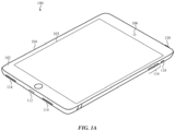
- FIG. 1A shows an example electronic device 100 embodied as a tablet computer (e.g., an example of a portable electronic device). While the device 100 is a tablet computer, the concepts presented herein may apply to any appropriate electronic device, including wearable devices (e.g., smartwatches), laptop computers, handheld gaming devices, mobile phones (e.g., smartphones), or any other device that incorporates input devices (e.g., buttons) and biometric input systems (e.g., fingerprint sensors). Accordingly, any reference to an "electronic device” encompasses any and all of the foregoing.
- wearable devices e.g., smartwatches
- laptop computers handheld gaming devices
- mobile phones e.g., smartphones
- biometric input systems e.g., fingerprint sensors
- the device 100 may also include buttons, switches, and other types of physical input devices.
- the device 100 may include buttons 116, switches 118, a fingerprint-sensing button 120 (or other type of biometric-sensing button), and/or other physical input systems.
- Such input systems may be used to control various operations and functions of the device 100.
- the buttons 116 may be operative to change speaker volume
- the switch 118 may be operative to switch between "ring" and "silent" modes.
- the fingerprint-sensing button 120 may include a fingerprint sensor or components thereof. The fingerprint sensor may be configured to capture an image or other representative data of a finger that is in contact with the fingerprint-sensing button 120.
- the display 103 may be at least partially positioned within the interior volume defined by the housing 104.
- the display 103 may be coupled to the transparent cover 102, such as via an adhesive or other coupling scheme.
- the assembly that includes the display 103 and the transparent cover 102 may be referred to as a top module.
- the top module may also include other components, such as touch- and/or force-sensing components, structural members, cameras, biometric sensors (e.g., facial recognition systems), ambient light sensors, or the like.
- the device 100 may also include a front-facing camera 106.
- the front-facing camera 106 may be positioned below or otherwise covered and/or protected by the cover 102.
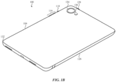
- FIG. 1B illustrates a back side of the device 100.
- the device 100 may include a back cover 132 coupled to the housing 104.
- the back cover 132 may include a substrate formed of glass, though other suitable materials may alternatively be used (e.g., plastic, sapphire, ceramic, ceramic glass, etc.).
- the back cover 132 may define a back exterior surface of the device 100.
- the back cover 132 may include one or more decorative layers on the exterior or interior surface of the substrate. For example, one or more opaque layers may be applied to the interior surface of the substrate (or otherwise positioned along the interior surface of the substrate) to provide a particular appearance to the back side of the device 100.
- the opaque layer(s) may include a sheet, ink, dye, or combinations of these (or other) layers, materials, or the like. In some cases the opaque layer(s) have a color that substantially matches a color of the housing 104 (e.g., the exterior surfaces of the housing members and the joint structures).
- the device 100 may also include a rear-facing camera 134 and a flash 136 that is configured to illuminate a scene to facilitate capturing images with the camera 134.
- the flash 136 is configured to illuminate a scene to facilitate capturing images with the camera 134.
- the flash 136 may include one or more light sources, such as one or more light emitting diodes (e.g., 1, 2, 3, 4, or more LEDs).
- the device may take an action such as unlocking the device, initiating a payment, activating a display of the device, opening or launching an application, or the like.
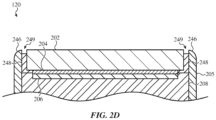
- the fingerprint-sensing button 120 may include a cap 202, such as a sapphire cap.
- the cap 202 may be attached to the chassis portion 205 of the button member 200 via an adhesive 210.
- the adhesive 210 may be a heat-activated adhesive, such as a heat-activated film, or any other suitable adhesive (e.g., a pressure-sensitive adhesive, an epoxy, etc.).
- the adhesive 210 may retain the cap 202 in place and securely attached to the chassis portion 205.
- a sealing material such as a curable liquid, may be introduced into a gap or space between the cap 202 and the chassis portion 205.
- the sealing material may help prevent liquids or other materials, such as water, sweat, lotions, sunscreen, or the like, from getting into the space between the cap 202 and the chassis portion 205, which may help improve the integrity and reliability of the fingerprint sensing component 204.
- the input sensor 228 may be conductively coupled to the flexible circuit element 238, which may be mounted to or otherwise in contact with a bracket 226.
- the bracket 226 may be secured to the housing member 203 via fasteners 230, or otherwise secured to the housing 104 and/or device 100.
- the flexible circuit element 238 may conductively couple both the input sensor 228 and the fingerprint sensing component 204 (via the flexible circuit element 212) to other components within the device, such as a processor or other circuitry.
- the anti-roll bar 239 may help evenly distribute the forces between the posts 220, 222 so that even an offset force on the button member 200 results in the posts 220, 222 moving in unison and the input surface of the button (e.g., the cap 202) remaining perpendicular to the input force as it is being pressed and/or translated.
- sealing members 218 may be positioned around the posts 220, 222 and in contact with the posts 220, 222 and the side walls of the holes 214, 215.
- the sealing members 218 are O-rings formed of an elastomeric material (e.g., rubber), which may be retained in channels or grooves formed in the posts 220, 222 (as shown), or they may be retained in channels or grooves formed in the side walls of the holes 214, 215.
- Other sealing members may be used instead of or in addition to the O-rings, such as insert-molded polymer seals, wipers, bushings, or the like.
- a waterproof seal may refer to a seal (which may be formed by one or more components or structures) that is configured to inhibit ingress of liquid.
- a waterproof seal may achieve an ingress protection rating, such as at least IP61, IP62, IP63, IP64, IP65, IP66, IP67, IP68, or IP69, as defined by IEC 60529.
- the holes 214, 215 through the housing member 203 allow physical access through the housing so that the button member can actuate an input sensor
- access into the housing must also be provided so that the fingerprint sensing component, which by necessity must be externally accessible by a user, can be conductively coupled to components within the housing 104.
- access for the fingerprint sensing component 204 may be provided through a hollow post. For example, as shown in FIG.
- the post 222 may be a hollow post that defines a passage that extends from an opening in the chassis portion 205 (e.g., where the fingerprint sensing component 204 is located) to an opening 224 that is past the sealing member 218 and communicates with the internal volume of the device 100.
- the flexible circuit element 212 may extend through the hollow post 222 to conductively couple the fingerprint sensing component 204 to the flexible circuit element 238 (or any other suitable component, circuit board, conductive connector, or the like).
- a second waterproof seal may be formed within the hollow post 222.
- a potting material 208 may be positioned in the hollow post 222 to at least partially encapsulate the flexible circuit element 238 and to form a waterproof seal within the hollow post 222.
- the potting material 208 may fill spaces and gaps in the fingerprint-sensing button 120 more generally.
- the potting material 208 may contact and/or at least partially encapsulate the fingerprint sensing component 204, the substrate 206, the back of the cap 202, or the like.
- the potting material 208 may thus fill substantially all of the voids defined between the button member 200 and the components that are coupled to the button member 200 (e.g., the cap 202, the fingerprint sensing component 204, etc.), thereby preventing ingress of liquid into the device through the hollow post 222 (and through the button member 200 more generally). Because the potting material 208 extends around the fingerprint sensing component 204 and other components, it effectively prevents liquids or other contaminants from contacting and potentially damaging those components as well.
- the potting material 208 may be positioned in the hollow post 222, and in the voids between the button member 200 and the other components, by flowing a liquid or otherwise flowable material into place, and then allowing the liquid or flowable material to cure or otherwise harden.
- the potting material 208 may be an epoxy, glue, polymer, or another suitable material.
- the potting material 208 may be introduced in various ways and via various entry points. For example, the potting material 208 may be flowed, injected, or otherwise introduced through a hole 255 defined through the chassis portion 205 of the button member 200. Instead of or in addition to flowing through the hole 255, the potting material 208 may be flowed, injected, or otherwise introduced through the hollow post 222.
- the adhesive 210 may include two discrete adhesive layers positioned at the longitudinal ends of the cap 202.
- the potting material 208 may work in conjunction with the adhesive 210 to secure the cap 202 (as well as the fingerprint sensing component 204 and substrate 206 which may be secured to the cap 202 prior to assembly of the cap 202 to the button member 200) to the button member 200.
- the potting material 208 may bond to and/or mechanically engage features of the substrate 206, fingerprint sensing component 204, and the cap 202, as well as bonding to and/or mechanically engaging features of the button member 200.
- the bonding and/or mechanical engagement (e.g., mechanical interlocks) provided by the potting material 208 may help retain the cap 202, fingerprint sensing component 204, and substrate 206 to the button member 200.
- the potting material 208 is in a cured or hardened condition, though it will be understood that this is for illustrative purposes, and that the potting material 208 is not installed or assembled in a cured or hardened state, but rather is flowed into place and allowed to cure after the cap 202 is attached to the button member 200 (e.g., via the adhesive 210).
- the potting material 208 may be flowed into place.
- the potting material 208 may abut the sealing material, forming intimate contact with the sealing material 248, thereby further enhancing the waterproof seals provided by the potting material 208 and the sealing material 248.
- the sealing material 248 may perform several functions. For example, it acts as a barrier so that liquids such as water, sweat, lotion, sunscreen, and the like cannot enter into the gap 249 where it could potentially become trapped, travel further into the button member, or damage components in the button member (e.g., the fingerprint sensing component 204 or other electrical or conductive components). Additionally, the sealing material 248 helps ensure that the conductive properties of the materials near the fingerprint sensing component 204 remain relatively constant and are not affected by different liquids or other materials being introduced into the gap 249.
- the shaft 256 may be allowed to rotate within the recess 254, but translation of the shaft (at least along the actuation direction of the fingerprint-sensing button) may be limited or constrained.
- the posts 220, 222 move inwards along an actuation direction, causing the anti-roll bar 239 to pivot or rotate within the recess 254.
- binding or twisting of the fingerprint-sensing button 120 due to off-center applications of force to the button may be reduced or eliminated.
- any inward motion of one of the posts 220, 222 essentially causes the other post to be pulled inward by substantially the same amount, even if no force or less force is being applied directly over the other post.
- FIG. 2E shows the anti-roll bar 239 retained to the housing via the shaft 256 being positioned in the recess 254, this is merely one example configuration. In some cases, instead of or in addition to a recess, the anti-roll bar 239 may be retained to the housing via clips, brackets, fasteners, and/or the like.
- the bracing member 312 may help position the flexible circuit element 212 away from the inner surfaces of the hollow post 222. In this way, the flexible circuit element 212 may be protected from accidental electrical shorting to the button member 200, and/or other potential damage that may occur from contacting the inner surfaces of the hollow post 222 during assembly.
- the bracing member 312 may also maintain the flexible circuit element 212 in a target position within the hollow post 222 during the introduction and curing of the potting material 208 so that the flexible circuit element 212 does not move to an undesirable position within the post or otherwise become out-of-position during the potting process.
- FIG. 4B is a partial cross-sectional view of the fingerprint sensing button 403, corresponding to a view along line 2B-2B in FIG. 2A .
- the fingerprint-sensing button 403 may include a cap 406 attached to the button member 400 via an adhesive 410.
- a sealing material 414 may be positioned in a gap between the cap 406 and surfaces of the button member 400, and a potting material 412 may at least partially fill the hollow post 402.
- the potting material 412 may also at least partially encapsulate a flexible circuit element 426 and a sensing stack 408 (which may include a fingerprint sensing component, a substrate, and optionally other electrical or other components).
- the fingerprint-sensing button 403 may also include a plate 416 coupled to the button member 400 (e.g., via fasteners 418 or any other suitable attachment component(s) or technique(s)).
- the plate 416 may overlap a portion of the housing member 401 to retain the button member 400 to the device.
- the plate 416 may also define a hole 424 through which the flexible circuit element 426 may extend.
- the plate 416 may also be configured to contact an input sensor 420, such as a dome switch, capacitive force sensor, strain gauge, or the like. When the button member 400 is pressed, the button member 400 may compress or otherwise impart a force on the input sensor 420, which the device may recognize as an input and perform an appropriate action.
- the input sensor 420 may be conductively coupled to a circuit element (e.g., a flexible circuit element) 430, which is also conductively coupled to other components of the device (e.g., a processor).
- the flexible circuit element 426 may also be conductively coupled to the circuit element 430, thereby facilitating a conductive coupling between the fingerprint sensing component and other components of the device (e.g., a processor).
- a frame 428 may be coupled to the housing member 401 and may support the input sensor 420 and the circuit element 430.
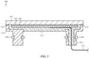
- FIG. 5 is a partial cross-sectional view of an example configuration for a button assembly 500 that includes a button member and cap of a fingerprint-sensing button.
- a button assembly 500 that includes a button member and cap of a fingerprint-sensing button.
- other button members described herein define a rim that surrounds the sides of the cap (and optionally defines a ground path to a user's finger)
- FIG. 5 illustrates an example button member in which the cap is not surrounded by a rim of the button member.
- the button assembly 500 includes a cap 502 that is attached, along the bottom surface of the cap 502, to a button member 516 by an adhesive 510.
- the adhesive 510 may be configured to define a waterproof seal between the cap 502 and the button member 516.
- the sides of the cap 502 are exposed and/or are not surrounded by a rim or other structure of the button member 516.
- a fingerprint-sensing button using the configuration shown in FIG. 5 may have a smaller outside dimension and/or occupy less volume than a fingerprint-sensing button that includes a rim around the outer periphery of the cap.
- the button member 516 of FIG. 5 also defines a hollow post 518 through which a flexible circuit element 512 may extend.
- a potting material 514 may also at least partially fill the hollow post and at least partially encapsulate the flexible circuit element 512 and a fingerprint sensing component 504 and/or substrate 506.
- the potting material 514 may define a waterproof seal within the hollow post 518, and the sealing members 508 may be coupled to the posts of the button member 516 to define a waterproof seal between the button member 516 and a housing of a device.
- the components shown in FIG. 5 may be embodiments of or otherwise similar to the corresponding components described with respect to other fingerprint-sensing buttons described herein. Details of those components will be understood to apply equally to those shown in FIG. 5 , and as such their details will not be repeated here.
- the button member and more particularly the base portion 605 of the button member, may be secured to the housing member 603 via fasteners 620, and/or via any other suitable attachment system or technique (e.g., adhesives, mechanical interlocks, clips, rivets, etc.).
- any other suitable attachment system or technique e.g., adhesives, mechanical interlocks, clips, rivets, etc.
- the fingerprint-sensing buttons shown in FIGS. 2B and 4B are configured to move (e.g., translate) relative to a housing member so that an input sensor can be compressed, moved, or otherwise subjected to a force
- the button member in FIG. 6A may be fixed in position relative to the housing member 603.
- the force sensor (or a portion thereof) may be integrated into the button member such that any motion or deformation necessary to detect a force is provided within the button member itself.
- the fingerprint sensing button 600 also includes a cap 602 and a fingerprint sensing component 604 below the cap 602.
- the cap 602 and fingerprint sensing component 604 may be similar to or embodiments of other caps and fingerprint sensing components described herein, and the details of those components are not repeated here for brevity.
- the fingerprint sensing component 604 may be conductively coupled to a flexible circuit element 606, such as a flexible circuit board, that conductively couples the fingerprint sensing component 604 to other components of a device (e.g., a processor).
- the second sensing portion 612 and the first sensing portion 607 may be separated by a gap 622 (which may be an air-gap or it may include a compliant material such as a foam, elastomer, potting material, or the like).
- the second sensing portion 612 of the flexible circuit element 606 may be positioned on a bracket 624, which is secured to the base portion 605.
- flexible circuit elements may be used to conductively couple components of fingerprint sensing buttons to other components within a device.
- the flexible circuit elements, or portions thereof may employ other types of conductive members.
- wires, wire bundles, or other flexible conductors may also be used.
- rigid circuit boards may be used in place of portions of flexible circuit elements.
- the first and second sensing portions 607, 612 of the flexible circuit element 606 may use rigid circuit substrates, which may be coupled together via a loop portion that includes a flexible circuit element.
- the fingerprint-sensing button 701 includes a button structure 702 that includes a chassis 704 and a cap 705 attached to the chassis 704.
- the chassis 704 may be formed from aluminum, stainless steel, titanium, ceramic, an amorphous metal, a polymer, or any other suitable material(s).
- the cap 705 may be attached to the chassis 704 via an adhesive 709.
- the adhesive 709 may be a heat-activated adhesive, such as a heat-activated film, or any other suitable adhesive (e.g., a pressure-sensitive adhesive, an epoxy, etc.). The adhesive 709 may retain the cap 705 in place and securely attached to the chassis 704.
- the cap 705 may cover a fingerprint-sensing component 706, and may define an input surface of the fingerprint-sensing button 701. A user may touch the input surface so that his or her fingerprint can be imaged by the fingerprint sensor for user authentication. When the fingerprint-sensing button 701 is being operated as a conventional button, the user may also contact the input surface to provide the requisite input or actuation force to the fingerprint-sensing button 701.
- the cap 705 may be formed from sapphire, glass, ceramic, glass ceramic, plastic, or another suitable material.
- the cap 705 may be a single piece of material or multiple components assembled together.
- the cap 705 may be formed of a material or materials that permit biometric sensing therethrough.
- the fingerprint sensing component 706 may be a capacitive sense layer that is configured to capture an image of a fingerprint of a user to authenticate the user.
- the fingerprint sensing component 706 may be coupled to a circuit component 707, and a flexible circuit element 708 may be conductively coupled to the fingerprint sensing component 706 (optionally via conductors of the circuit component 707).
- the circuit component 707 may be a system-in-package that includes multiple electronic components in a single carrier.
- the system-in-package circuit component 707 may include electronic components such as a processor, memory, and/or other components used for biometric sensing on a single substrate.
- the flexible circuit element 708 may conductively couple the fingerprint sensing component 706 (or other biometric sensing component) to a component within the housing of the device, in the same or similar manner to the flexible circuit element 212 described above.
- the fingerprint sensing component 706 and the circuit component 707 may be attached to the cap 705, such as via adhesive. In some cases, neither the fingerprint sensing component 706 nor the circuit component 707 contact the chassis 704.
- the button member 702 may be coupled to a compressible support assembly 710.
- the button member 712 may be attached via adhesive, fasteners, fusion bonds (e.g., welding), staking (e.g., heat staking), brazing, soldering, or the like.
- an upper surface of the compressible support assembly 710 e.g., an upper surface of a movable member 711
- a bottom surface of the chassis 714 e.g., an upper surface of a movable member 711
- the compressible support assembly 710 provides multiple functions to the fingerprint-sensing button 701. For example, the compressible support assembly 710 biases the button structure 702 towards an unactuated position (e.g., fully extended and/or undepressed), while also retaining the button structure 702 to the device. The compressible support assembly 710 also transfers input forces applied to the button structure 702 to an input sensor. Further, the compressible support assembly 710 acts as a multi-interface sealing structure to inhibit ingress of water, liquids, and/or other contaminants into the device. In some cases, the seals defined by the compressible support assembly 710 are waterproof seals.
- the compressible support assembly 710 includes a movable member 711 and a stationary member 712.
- the movable member 711 is coupled to and supports the button structure 702.
- a bottom side of the chassis 704 may be adhered to or otherwise attached to an upper surface of the movable member 711.
- the stationary member 712 may act as one side of a clamping structure that secures the compressible support assembly 710, and thus the button structure 702, to the device housing.
- the stationary member 712 and an inner bracket 713 may together act as a clamping structure that engages or clamps onto a portion of the housing 703.
- the stationary member 712 and the inner bracket 713 may capture flanges 714 of the housing 713 between clamping surfaces of the stationary member 712 and the inner bracket 713.
- Fasteners 715 e.g., screws
- the compressible support assembly 710 also includes biasing springs 716 that bias the movable member 711 (and thus the button structure 702) towards an unactuated position (e.g., fully extended and/or undepressed).
- the biasing springs 716 may be positioned between the movable member 711 and the stationary member 712, and an input force applied to the button structure 702 may cause the biasing springs 716 to be compressed between the movable member 711 and the stationary member 712.
- the biasing springs 716 may be coil springs (as shown), or any other suitable type of spring or resilient member or material (e.g., leaf springs, beam springs, elastomer, etc.).
- the movable member 711 may be retained to the stationary member 712 via retention pins 720.
- the retention pins 720 may include a flange or other feature that engages the movable member 711 to limit its travel in one direction (e.g., outwards or towards an unactuated position).
- the biasing springs 716 may bias the movable member 711 against the retention pins 720, thereby defining the outward-most position of the button structure 702 (e.g., defining the unactuated position).
- the retention pins 720 may be attached to the stationary member 712.
- retention clips 721 e.g., c-clips or e-clips
- the retention pins 720 are fixed to the stationary member 712 via the retention clips 720.
- the movable member 711 may be configured to actuate an input sensor 719, such as a dome switch (as shown), capacitive force sensor, strain gauge, or the like.
- the input sensor 719 may be attached to or mounted on the inner bracket 713.
- the input sensor 719 may be conductively coupled to a circuit element via one or more electrical connectors (e.g., vias), which may extend through an opening or hole in the inner bracket 713, which is also conductively coupled to other components of the device (e.g., a processor).
- electrical connectors e.g., vias
- the movable member 711 may include or define an actuation structure 717 that engages a plunger 718 to impart the force on the input sensor 719 when the button is pressed.
- the plunger 718 is secured to the actuation structure 717 (e.g., via adhesive), while in some cases it contacts the actuation structure 717 but is not attached.
- the movable member 711 includes an actuation structure 717 that extends fully to the input sensor 719 to engage the input sensor 717 directly.
- the compressible support assembly 710 also seals the fingerprint-sensing button 701 to inhibit ingress of water, liquids, or other contaminants into the device. More particularly, the compressible support assembly 710 seals several interfaces of the fingerprint-sensing button 701, while leaving a large sealed environment in which electrical and mechanical components may be positioned.
- the compressible support assembly 710 includes a first seal 722, shown here as a skirt seal (and sometimes referred to as a skirt seal 722), that is coupled to the movable member 711 and seals an interface between the chassis 704 and the movable member 711.
- the skirt seal 722 includes a seal wall 801 that is configured to collapse, buckle, or otherwise deform when the button structure 702 is pressed (e.g., to actuate the input sensor 719), while keeping the sealed environment enclosed during button actuation.
- the compressible support assembly 710 also includes a second seal 723 that is coupled to the stationary member 712 and is coupled to the first seal 722, and is configured to seal an interface between the stationary member 712 and the housing 703 (e.g., a surface of the flange 714).
- the first seal 722 and the second seal 723 are further described with respect to FIGS. 8A-8B .
- the compressible support assembly 710 provides numerous mechanical and sealing functions to the fingerprint-sensing button 701.
- the compressible support assembly 710 biases the button structure 702 to an unactuated position, retains the button structure 702 to the device housing 703, serves as part of a clamping structure that secures the button structure 702 to the device housing, facilitates force transfer to an input sensor, provides a tactile response to a user when the button is being pressed (e.g., via the springs), and also seals multiple interfaces between components of the fingerprint-sensing button 701.
- the compressible support assembly 710 may be fully assembled prior to attachment to the chassis 704.
- the movable member 711 may be inserted into a mold, and a polymer material may be introduced into the mold and against the movable member 711 to form the first seal 722.
- the stationary member 712 (and optionally the retention pins 720, biasing springs 716, and actuation structure) may be introduced into the mold (or a different mold) along with the movable member 711 and the first seal 722, and another polymer material (which may have the same or a different composition as the first seal 722) may be introduced into the mold and against both the first seal 722 and the stationary member 712 to define the second seal 723.
- Retention clips 721 may then be included to secure the retention pins 720 to the stationary member 712. This process may result in a pre-assembled compressible support assembly 710 that can be attached to the chassis 704 and secured to the housing 703 to efficiently and quickly provide mechanical button functionality and define reliable seals for the fingerprint-sensing button 701.
- the compressible support assembly 710 defines a sealed chamber 730 below the button structure 702.
- the sealed chamber 730 is positioned over and/or encompasses holes formed through the housing 703.
- the holes in the housing 703 allow mechanical and/or electrical components to pass through into the interior of the housing 703. Thus, because the holes are within the sealed chamber 730, those components are protected from liquids, water, or other contaminants.
- the flexible circuit element 708 is coupled to the circuit component 707 and passes through the sealed chamber 730 and into the device through a hole 728 in the inner bracket 713.
- the flexible circuit element 708 carries electrical signals between the circuit component 707 and other electrical components of the device 700 (e.g., a processor, main logic board, etc.).
- the electrical signals may include signals from the fingerprint sensing component 706.
- the sealed chamber 730 is sealed from the exterior environment, and because the sealed chamber 730 is relatively large (e.g., encompassing up to 90% or more of the area below the chassis 704), the flexible circuit element 708 can pass freely through the sealed chamber 730, optionally without additional sealing structures. Further, the large volume of the sealed chamber 730 allows sufficient room for the flexible circuit element 708 to flex or bend during button actuations, and allows the flexible circuit element 708 to be routed into the device housing 703 without tight bends or curves.
- an inner bracket 713 may operate as one side of a clamping structure that secures the compressible support assembly 710 to the housing 703.
- the inner bracket 713 also secures a microphone module 724 to the housing 703.
- a wing portion 726 of the inner bracket 713 may be configured to extend along a portion of an interior surface of the housing that includes a recess for the microphone module 724. The wing portion 726 may hold the microphone module 724 in the recess.
- the same clamping configuration from the inner bracket 713 and the compressible support assembly 710 retains the microphone module 724 in place.
- the wing portion 726 is rigidly held in the position that secures the microphone module 724 in place. In some cases, no additional fasteners are needed to retain the microphone module 724 in place in its recess. In some cases, a biasing member such as a foam pad is positioned between the wing portion 726 and the microphone module 724 to help bias the microphone module against the housing 703.
- the microphone module 724 may receive sound through a hole 725 formed through the housing 703.
- FIGS. 8A-8B depict a portion of the device 700 corresponding to area 8A-8A in FIG. 7 , illustrating details of the first and second seals 722.
- FIG. 8A shows the button in an unactuated state, such as may occur when the fingerprint sensing button 701 is not being subjected to an input force (e.g., it is not being pressed). In this state, the biasing springs may be forcing the movable member 711 into its outward most position.
- the first seal 722 is attached to the movable member 711 such as via injection molding, such that the first seal 722 is bonded to the movable member 711 and defines a water-tight seal between the first seal 722 and the movable member 711.
- the first seal 722 defines a first sealing feature 802 that contacts the chassis 704.
- the first sealing feature 802 which may be a protrusion, bump, or any other suitable shape or configuration, may seal against a surface of the chassis 704 to define a sealing interface between the first seal 722 and the chassis 704.
- the first sealing feature 802 may be deformed against the chassis 704 (e.g., compressed) due to the size of the first sealing feature 802 being larger than the gap between the sealing surface of the chassis 704 and the movable member 711.
- the second seal 723 is attached to the stationary member 712 such as via injection molding, such that the second seal 723 is bonded to the stationary member 712 and defines a water-tight seal between the second seal 723 and the stationary member 712. Accordingly, the interface between the second seal 723 and the stationary member 712 may be water-tight.
- the second seal 723 defines a second sealing feature 805 that contacts the housing 703 (e.g., the flange 714 of the housing 703).
- the second sealing feature 805 which may be a protrusion, bump, or any other suitable shape or configuration, may seal against a surface of the housing (e.g., the flange 714) to define a sealing interface between the second seal 723 and the housing 703.
- the second sealing feature 805 may be deformed against the flange 714 (e.g., compressed) due to the size of the second sealing feature 805 being larger than the gap between the sealing surface of the flange 714 and the stationary member 712.
- the first seal 722 is also attached to the stationary member 712, and optionally attached to the second seal 723.
- the second seal 723 may be attached to an end portion 803 of the first seal 722, along a bond interface 804 (e.g., where the first and second seals 722, 723 are bonded to each other).
- the attachment between the first seal 722 and the stationary member 712 and second seal 723 may result from the injection process, in which the second seal 723 bonds to the first seal 722 and to the stationary member 712.
- the bonds between the first seal 722 and the movable member 711, between the first seal 722 and the second seal 723, and between the second seal 723 and the stationary member 712 defines a boot-like seal around the periphery of the compressible support assembly 710, and thus defines the sealed chamber 730.
- the sealed chamber 730 is thus sealed against ingress of water, liquids, or other contaminants, and allows a large area below the button structure 702 to be open to the interior of the housing.
- This large, environmentally sealed area can contain many mechanical and electrical components that would otherwise not be suitable for free environmental contact (e.g., flexible circuit elements, input sensors, fingerprint sensing components, circuit boards, etc.).
- FIG. 8B illustrates the fingerprint-sensing button 701 in a depressed or actuated state, such as may occur when a user presses on the button member to provide an input to a device.
- the button structure 702 including the chassis 704 and the movable member 711 are moved downwards (e.g., towards the stationary member 712), resulting in the first seal 722 deforming along a seal wall 801.
- the sealing wall 801 deforms during button actuation, the seal remains intact during the button actuation.
- neither of the sealing interfaces have to move or slide along a sealing surface during button actuation.
- the first sealing feature 802 remains static against the sealing surface of the chassis 704, while the second sealing feature 805 remains static against the sealing surface of the ledge 714.
- movement of the button does not apply forces to or produce friction on the sealing features, leading to less wear and greater durability.
- the seals may be stronger or less likely to allow ingress of liquid, water, etc.
- the configuration of a deformable sealing wall 801 with static sealing features provides a robust seal that may have a greater sealing effect and durability as compared to seals that move or slide against surfaces during actuation.
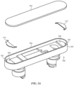
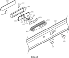
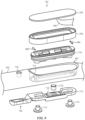
- FIG. 9 is a partial exploded view of the fingerprint-sensing button 701, illustrating an example of how the components of the fingerprint-sensing button 701 and the device housing 701 are arranged.
- FIG. 9 may also illustrate how the fingerprint-sensing button 701 may be assembled.
- the cap 705, which may have circuit components including a flexible circuit element 708 coupled to a bottom surface thereof, is coupled to a top side of the chassis 704.
- the compressible support assembly 710 may also be coupled to a bottom side of the chassis 704.
- the compressible support assembly 710 may be secured to flange or other mounting surface of the chassis 704 via adhesive 900 (which may be adhesive film, a curable liquid adhesive, or the like).
- adhesive 900 which may be adhesive film, a curable liquid adhesive, or the like.
- the process of attaching the compressible support assembly 710 to the chassis 704 results in the first sealing feature 802 ( FIGS. 8A-8B ) being forced against the chassis 704 to form a watertight seal between the chassis 704 and the first seal 722.
- the flexible circuit element 708 may be routed through the central hole of the chassis 704 and through the sealed chamber 730 of the compressible support assembly 710.
- cap 705, chassis 704, and compressible support assembly 710 may be positioned in a hole 901 in the housing 703, and the flexible circuit element 708 may be routed through a hole in the inner bracket 713.
- the fasteners 715 may be installed to secure the inner bracket 713 (with the input sensor 719) to the compressible support assembly 710, thereby clamping the flange 714 of the housing 703 between the compressible support assembly 710 and the inner bracket 713 and securing the fingerprint-sensing button 701 to the housing 703.
- the clamping interface has a ring-like shape that extends around a large sealed area through which components may pass while remaining within the sealed environment.
- the process of clamping the flange 714 of the housing 703 between the compressible support assembly 710 and the inner bracket 713 also results in the second sealing feature 805 ( FIGS. 8A-8B ) being forced against the housing (e.g., the flange 714) to form a watertight seal between the flange 714 of the housing 703 and the second seal 723.
- a microphone module may be positioned in a recess in the housing 703, such that attaching the inner bracket 713 to the compressible support assembly 710 results in the wing portion 726 of the inner bracket 713 retaining the microphone module in place.
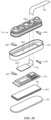
- FIG. 10 is another partial exploded view of the fingerprint-sensing button 701, illustrating how the components of the fingerprint-sensing button 701 and the device housing 701 are arranged.
- the fingerprint-sensing component 706 may be attached to a bottom side surface of the cap 705 with an adhesive 1001, such as an adhesive film, a curable liquid adhesive, or the like.
- the circuit component 707 which may be a system-in-package circuit component, may be conductively coupled to the fingerprint-sensing component 706.
- the fingerprint-sensing component 706 may include one or more electrode layers for capacitively sensing details of a user's fingerprints
- the circuit component 707 may include processors, memory, and/or other circuitry that are conductively coupled to the electrode layers (and/or other components of the fingerprint-sensing component 706) to facilitate fingerprint sensing.
- the circuit component 707 may be attached to the fingerprint-sensing component 706 with an adhesive, such as an adhesive film, a curable liquid adhesive, or the like.
- the flexible circuit element 708 may include a connector 1003 that conductively couples to the circuit element 707 and facilitates the flexible circuit element 708 in carrying electrical signals and/or other communications between the circuit element 707 and other electronic components of a device.
- the flexible circuit element 708 may be routed through a hole 1002 or open central region of the chassis 704, and through a hole 1004 in the compressible support assembly 710.
- the flexible circuit element 708 extends through the sealed chamber 730 and, more generally, is within the sealed environment defined by the sealing components of the fingerprint-sensing button 701.
- FIG. 11 depicts an example schematic diagram of an electronic device 1100.
- the electronic device 1100 may be an embodiment of or otherwise represent the device 100.
- the device 1100 includes one or more processing units 1101 that are configured to access a memory 1102 having instructions stored thereon.
- the instructions or computer programs may be configured to perform one or more of the operations or functions described with respect to the electronic devices described herein.
- the instructions may be configured to control or coordinate the operation of one or more displays 1108, one or more touch sensors 1103, one or more force sensors 1105, one or more communications channels 1104, one or more audio input systems 1109, one or more audio output systems 1110, one or more positioning systems 1111, one or more sensors 1112, and/or one or more haptic feedback devices 1106.
- the memory 1102 can store electronic data that can be used by the device 1100.
- a memory can store electrical data or content such as, for example, audio and video files, images, documents and applications, device settings and user preferences, programs, instructions, timing and control signals or data for the various modules, data structures or databases, and so on.
- the memory 1102 can be configured as any type of memory.
- the memory can be implemented as random access memory, read-only memory, Flash memory, removable memory, or other types of storage elements, or combinations of such devices.
- the memory 1102 may be coupled to a logic board of the device 1100.
- the touch sensors 1103 may detect various types of touch-based inputs and generate signals or data that are able to be accessed using processor instructions.
- the touch sensors 1103 may use any suitable components and may rely on any suitable phenomena to detect physical inputs.
- the touch sensors 1103 may be capacitive touch sensors, resistive touch sensors, acoustic wave sensors, or the like.
- the touch sensors 1103 may include any suitable components for detecting touch-based inputs and generating signals or data that are able to be accessed using processor instructions, including electrodes (e.g., electrode layers), physical components (e.g., substrates, spacing layers, structural supports, compressible elements, etc.) processors, circuitry, firmware, and the like.
- the touch sensors 1103 may be integrated with or otherwise configured to detect touch inputs applied to any portion of the device 1100.
- the touch sensors 1103 may be configured to detect touch inputs applied to any portion of the device 1100 that includes a display (and may be integrated with a display).
- the touch sensors 1103 may operate in conjunction with the force sensors 1105 to generate signals or data in response to touch inputs.
- a touch sensor or force sensor that is positioned over a display surface or otherwise integrated with a display may be referred to herein as a touch-sensitive display, force-sensitive display, or touchscreen.
- the force sensors 1105 may be used in conjunction with various input mechanisms to detect various types of inputs.
- the force sensors 1105 may be used to detect presses or other force inputs that satisfy a force threshold (which may represent a more forceful input than is typical for a standard "touch" input).
- the force sensors 1105 may be integrated with or otherwise configured to detect force inputs applied to any portion of the device 1100.
- the force sensors 1105 may be configured to detect force inputs applied to any portion of the device 1100 that includes a display (and may be integrated with a display).
- the force sensors 1105 may operate in conjunction with the touch sensors 1103 to generate signals or data in response to touch- and/or force-based inputs.
- Force sensors 1105 may be integrated with buttons (e.g., the fingerprint-sensing buttons 120, 403, 600, 701) to detect inputs applied to the buttons.
- the device 1100 may also include one or more haptic devices 1106.
- the haptic device 1106 may include one or more of a variety of haptic technologies such as, but not necessarily limited to, rotational haptic devices, linear actuators, piezoelectric devices, vibration elements, and so on.
- the haptic device 1106 may be configured to provide punctuated and distinct feedback to a user of the device. More particularly, the haptic device 1106 may be adapted to produce a knock or tap sensation and/or a vibration sensation.
- Such haptic outputs may be provided in response to detection of inputs such as touch and/or force inputs, or events such as a successful (or unsuccessful) biometric authentication.
- the haptic outputs may be imparted to a user through the exterior surface of the device 1100 (e.g., via a glass or other surface that acts as a touch- and/or force-sensitive display or surface), or via an input member such as a button or biometric sensor (e.g., the fingerprint-sensing button 120, FIG. 1A ).
- an input member such as a button or biometric sensor (e.g., the fingerprint-sensing button 120, FIG. 1A ).
- the wireless interface may communicate via, without limitation, radio frequency, optical, acoustic, and/or magnetic signals and may be configured to operate over a wireless interface or protocol.
- Example wireless interfaces include radio frequency cellular interfaces (e.g., 2G, 3G, 4G, 4G long-term evolution (LTE), 5G, GSM, CDMA, or the like), fiber optic interfaces, acoustic interfaces, Bluetooth interfaces, infrared interfaces, USB interfaces, Wi-Fi interfaces, TCP/IP interfaces, network communications interfaces, or any conventional communication interfaces.
- the one or more communications channels 1104 may also include ultra-wideband interfaces, which may include any appropriate communications circuitry, instructions, and number and position of suitable UWB antennas.
- the device 1100 may include a battery 1107 that is used to store and provide power to the other components of the device 1100.
- the battery 1107 may be a rechargeable power supply that is configured to provide power to the device 1100.
- the battery 1107 may be coupled to charging systems (e.g., wired and/or wireless charging systems) and/or other circuitry to control the electrical power provided to the battery 1107 and to control the electrical power provided from the battery 1107 to the device 1100.
- charging systems e.g., wired and/or wireless charging systems
- the device 1100 may also include one or more displays 1108 configured to display graphical outputs.
- the displays 1108 may use any suitable display technology, including liquid crystal displays (LCD), organic light emitting diodes (OLED) displays, active-matrix organic light-emitting diode displays (AMOLED), or the like.
- the displays 1108 may display graphical user interfaces, images, icons, or any other suitable graphical outputs.
- the display 1108 may correspond to the display 103 of FIG. 1A .
- the device 1100 may also provide audio input functionality via one or more audio input systems 1109.
- the audio input systems 1109 may include microphones, transducers, or other devices that capture sound for voice calls, video calls, audio recordings, video recordings, voice commands, and the like.
- the device 1100 may also include one or more additional sensors 1112 to receive inputs (e.g., from a user or another computer, device, system, network, etc.) or to detect any suitable property or parameter of the device, the environment surrounding the device, people or things interacting with the device (or nearby the device), or the like.
- a device may include temperature sensors, biometric sensors (e.g., fingerprint sensors, photoplethysmographs, blood-oxygen sensors, blood sugar sensors, or the like), eye-tracking sensors, retinal scanners, humidity sensors, buttons, switches, lid-closure sensors, or the like.
- the device 1100 may have some, none, or all of the various capabilities, apparatuses, physical features, modes, and operating parameters discussed herein.
- the systems included in the device 1100 are not exclusive, and the device 1100 may include alternative or additional systems, components, modules, programs, instructions, or the like, that may be necessary or useful to perform the functions described herein.
- the present disclosure recognizes that the use of such personal information data, in the present technology, can be used to the benefit of users.
- the personal information data can be used to deliver targeted content that is of greater interest to the user. Accordingly, use of such personal information data enables users to calculated control of the delivered content.
- other uses for personal information data that benefit the user are also contemplated by the present disclosure. For instance, health and fitness data may be used to provide insights into a user's general wellness, or may be used as positive feedback to individuals using technology to pursue wellness goals.
- the present disclosure contemplates that the entities responsible for the collection, analysis, disclosure, transfer, storage, or other use of such personal information data will comply with well-established privacy policies and/or privacy practices.
- such entities should implement and consistently use privacy policies and practices that are generally recognized as meeting or exceeding industry or governmental requirements for maintaining personal information data private and secure.
- Such policies should be easily accessible by users, and should be updated as the collection and/or use of data changes.
- Personal information from users should be collected for legitimate and reasonable uses of the entity and not shared or sold outside of those legitimate uses. Further, such collection/sharing should occur after receiving the informed consent of the users. Additionally, such entities should consider taking any needed steps for safeguarding and securing access to such personal information data and ensuring that others with access to the personal information data adhere to their privacy policies and procedures.
- policies and practices should be adapted for the particular types of personal information data being collected and/or accessed and adapted to applicable laws and standards, including jurisdiction-specific considerations. For instance, in the US, collection of or access to certain health data may be governed by federal and/or state laws, such as the Health Insurance Portability and Accountability Act (HIPAA); whereas health data in other countries may be subject to other regulations and policies and should be handled accordingly. Hence different privacy practices should be maintained for different personal data types in each country.
- HIPAA Health Insurance Portability and Accountability Act
- the present disclosure also contemplates embodiments in which users selectively block the use of, or access to, personal information data. That is, the present disclosure contemplates that hardware and/or software elements can be provided to prevent or block access to such personal information data.
- the present technology can be configured to allow users to select to "opt in” or “opt out” of participation in the collection of personal information data during registration for services or anytime thereafter.
- users can select not to provide mood-associated data for targeted content delivery services.
- users can select to limit the length of time mood-associated data is maintained or entirely prohibit the development of a baseline mood profile.
- personal information data should be managed and handled in a way to minimize risks of unintentional or unauthorized access or use. Risk can be minimized by limiting the collection of data and deleting data once it is no longer needed.
- data de-identification can be used to protect a user's privacy. De-identification may be facilitated, when appropriate, by removing specific identifiers (e.g., date of birth, etc.), controlling the amount or specificity of data stored (e.g., collecting location data at a city level rather than at an address level), controlling how data is stored (e.g., aggregating data across users), and/or other methods.
- the present disclosure broadly covers use of personal information data to implement one or more various disclosed embodiments, the present disclosure also contemplates that the various embodiments can also be implemented without the need for accessing such personal information data. That is, the various embodiments of the present technology are not rendered inoperable due to the lack of all or a portion of such personal information data.
- content can be selected and delivered to users by inferring preferences based on non-personal information data or a bare minimum amount of personal information, such as the content being requested by the device associated with a user, other non-personal information available to the content delivery services, or publicly available information.
- the phrase "at least one of” preceding a series of items, with the term “and” or “or” to separate any of the items, modifies the list as a whole, rather than each member of the list.
- the phrase "at least one of” does not require selection of at least one of each item listed; rather, the phrase allows a meaning that includes at a minimum one of any of the items, and/or at a minimum one of any combination of the items, and/or at a minimum one of each of the items.
- the phrases "at least one of A, B, and C" or “at least one of A, B, or C” each refer to only A, only B, or only C; any combination of A, B, and C; and/or one or more of each of A, B, and C.
- an order of elements presented for a conjunctive or disjunctive list provided herein should not be construed as limiting the disclosure to only that order provided.
Landscapes
- Engineering & Computer Science (AREA)
- Theoretical Computer Science (AREA)
- Computer Hardware Design (AREA)
- General Engineering & Computer Science (AREA)
- General Physics & Mathematics (AREA)
- Physics & Mathematics (AREA)
- Human Computer Interaction (AREA)
- Signal Processing (AREA)
- Computer Security & Cryptography (AREA)
- Computer Networks & Wireless Communication (AREA)
- Software Systems (AREA)
- Multimedia (AREA)
- Image Input (AREA)
- Casings For Electric Apparatus (AREA)
- Measurement Of The Respiration, Hearing Ability, Form, And Blood Characteristics Of Living Organisms (AREA)
- Electric Clocks (AREA)
Priority Applications (1)
| Application Number | Priority Date | Filing Date | Title |
|---|---|---|---|
| EP26150829.5A EP4730076A2 (fr) | 2020-09-25 | 2021-09-23 | Dispositif électronique ayant un système d'entrée biométrique scellé |
Applications Claiming Priority (4)
| Application Number | Priority Date | Filing Date | Title |
|---|---|---|---|
| US202063083610P | 2020-09-25 | 2020-09-25 | |
| US202163209769P | 2021-06-11 | 2021-06-11 | |
| US17/471,031 US12093359B2 (en) | 2020-09-25 | 2021-09-09 | Electronic device having a sealed biometric input system |
| EP21198698.9A EP3975529A1 (fr) | 2020-09-25 | 2021-09-23 | Dispositif électronique comportant un système d'entrée biométrique étanche |
Related Parent Applications (1)
| Application Number | Title | Priority Date | Filing Date |
|---|---|---|---|
| EP21198698.9A Division EP3975529A1 (fr) | 2020-09-25 | 2021-09-23 | Dispositif électronique comportant un système d'entrée biométrique étanche |
Related Child Applications (2)
| Application Number | Title | Priority Date | Filing Date |
|---|---|---|---|
| EP26150829.5A Division EP4730076A2 (fr) | 2020-09-25 | 2021-09-23 | Dispositif électronique ayant un système d'entrée biométrique scellé |
| EP26150829.5A Division-Into EP4730076A2 (fr) | 2020-09-25 | 2021-09-23 | Dispositif électronique ayant un système d'entrée biométrique scellé |
Publications (3)
| Publication Number | Publication Date |
|---|---|
| EP4398070A2 true EP4398070A2 (fr) | 2024-07-10 |
| EP4398070A3 EP4398070A3 (fr) | 2024-10-16 |
| EP4398070B1 EP4398070B1 (fr) | 2026-03-11 |
Family
ID=78085790
Family Applications (3)
| Application Number | Title | Priority Date | Filing Date |
|---|---|---|---|
| EP24163603.4A Active EP4398070B1 (fr) | 2020-09-25 | 2021-09-23 | Dispositif électronique ayant un système d'entrée biométrique scellé |
| EP26150829.5A Pending EP4730076A2 (fr) | 2020-09-25 | 2021-09-23 | Dispositif électronique ayant un système d'entrée biométrique scellé |
| EP21198698.9A Withdrawn EP3975529A1 (fr) | 2020-09-25 | 2021-09-23 | Dispositif électronique comportant un système d'entrée biométrique étanche |
Family Applications After (2)
| Application Number | Title | Priority Date | Filing Date |
|---|---|---|---|
| EP26150829.5A Pending EP4730076A2 (fr) | 2020-09-25 | 2021-09-23 | Dispositif électronique ayant un système d'entrée biométrique scellé |
| EP21198698.9A Withdrawn EP3975529A1 (fr) | 2020-09-25 | 2021-09-23 | Dispositif électronique comportant un système d'entrée biométrique étanche |
Country Status (3)
| Country | Link |
|---|---|
| US (2) | US12093359B2 (fr) |
| EP (3) | EP4398070B1 (fr) |
| CN (3) | CN119336129A (fr) |
Families Citing this family (6)
| Publication number | Priority date | Publication date | Assignee | Title |
|---|---|---|---|---|
| US11275920B1 (en) | 2017-09-27 | 2022-03-15 | Apple Inc. | Elongated fingerprint sensor |
| US11189248B1 (en) | 2020-05-06 | 2021-11-30 | Apple Inc. | Systems and methods for switching vision correction graphical outputs on a display of an electronic device |
| KR102880120B1 (ko) * | 2020-10-16 | 2025-11-04 | 삼성전자주식회사 | 사이드 키를 포함하는 전자 장치 |
| US20220205284A1 (en) * | 2020-12-28 | 2022-06-30 | Steven Wai-Tong Cheung | Device compatible enclosure apparatus |
| US11783629B2 (en) | 2021-03-02 | 2023-10-10 | Apple Inc. | Handheld electronic device |
| US20250278139A1 (en) * | 2024-03-04 | 2025-09-04 | Qorvo Us, Inc. | Two-function push trigger |
Family Cites Families (120)
| Publication number | Priority date | Publication date | Assignee | Title |
|---|---|---|---|---|
| US6853336B2 (en) | 2000-06-21 | 2005-02-08 | International Business Machines Corporation | Display device, computer terminal, and antenna |
| US6834181B2 (en) | 2002-03-13 | 2004-12-21 | Nokia Corporation | Mobile communication device and related construction method |
| CN100365658C (zh) | 2002-06-12 | 2008-01-30 | 奥普提克斯晶硅有限公司 | 用于光学异常的电子校正的系统和方法 |
| FR2844405B1 (fr) | 2002-09-05 | 2004-12-03 | Cit Alcatel | Agencement structurel pour terminal de radiocommunication comportant un haut-parleur et un ecouteur |
| DE102004016155B3 (de) | 2004-04-01 | 2006-05-24 | Infineon Technologies Ag | Kraftsensor mit organischen Feldeffekttransistoren, darauf beruhender Drucksensor, Positionssensor und Fingerabdrucksensor |
| CN100495187C (zh) | 2004-04-03 | 2009-06-03 | 孙犁 | 用于2d和3d显示的双偏振光滤光器 |
| EP1754180A1 (fr) | 2004-04-16 | 2007-02-21 | Validity Sensors Inc. | Procede et dispositif de detection de la position d'un doigt |
| US7409058B2 (en) | 2004-06-01 | 2008-08-05 | Research In Motion Limited | Display cover for a communication device |
| KR100724116B1 (ko) | 2005-08-24 | 2007-06-04 | 엘지전자 주식회사 | 내장형 안테나를 구비한 이동통신 단말기 |
| JP4003791B2 (ja) | 2005-10-19 | 2007-11-07 | セイコーエプソン株式会社 | プロジェクタ |
| US7620175B2 (en) | 2006-07-24 | 2009-11-17 | Motorola, Inc. | Handset device with audio porting |
| US7452077B2 (en) | 2006-08-29 | 2008-11-18 | Carl Zeiss Meditec, Inc. | Image adjustment derived from optical imaging measurement data |
| US20080102963A1 (en) | 2006-10-30 | 2008-05-01 | David Scott Flagg | Internally illuminated video game cabinet |
| US8207897B2 (en) | 2008-12-18 | 2012-06-26 | Motorola Mobility, Inc. | Radio device and slot antenna which facilitates operation of a user interface element |
| KR101636461B1 (ko) | 2009-03-20 | 2016-07-05 | 삼성전자주식회사 | 휴대용 단말기에서 음향 기기의 소리 입·출력 홀 구조 |
| JP2010257089A (ja) | 2009-04-22 | 2010-11-11 | Xiroku:Kk | 光学式位置検出装置 |
| US20150309316A1 (en) | 2011-04-06 | 2015-10-29 | Microsoft Technology Licensing, Llc | Ar glasses with predictive control of external device based on event input |
| WO2011112752A1 (fr) | 2010-03-09 | 2011-09-15 | Alejandro Diaz Arceo | Techniques de transaction électronique mises en œuvre sur un réseau informatique |
| US10054430B2 (en) | 2011-08-09 | 2018-08-21 | Apple Inc. | Overlapping pattern projector |
| JP5214782B2 (ja) | 2011-08-31 | 2013-06-19 | 株式会社東芝 | メモリ装置、ストレージメディア、ホスト装置、及びシステム |
| US9030440B2 (en) | 2012-05-18 | 2015-05-12 | Apple Inc. | Capacitive sensor packaging |
| CN102709086A (zh) | 2012-05-28 | 2012-10-03 | 鸿富锦精密工业(深圳)有限公司 | 按键及带有该按键的电子装置 |
| US10068396B2 (en) | 2016-01-15 | 2018-09-04 | John C. S. Koo | Light-based security systems |
| US10679448B2 (en) | 2012-07-26 | 2020-06-09 | John C. S. Koo | Light-based commercial messaging systems |
| US9651513B2 (en) | 2012-10-14 | 2017-05-16 | Synaptics Incorporated | Fingerprint sensor and button combinations and methods of making same |
| US20140137054A1 (en) | 2012-11-14 | 2014-05-15 | Ebay Inc. | Automatic adjustment of font on a visual display |
| NO20131423A1 (no) | 2013-02-22 | 2014-08-25 | Idex Asa | Integrert fingeravtrykksensor |
| US20140282285A1 (en) | 2013-03-14 | 2014-09-18 | Cellco Partnership D/B/A Verizon Wireless | Modifying a user interface setting based on a vision ability of a user |
| FR3008805B3 (fr) | 2013-07-16 | 2015-11-06 | Fittingbox | Procede de determination de mesures oculaires avec un capteur grand public |
| US20150302773A1 (en) | 2013-07-29 | 2015-10-22 | Fusao Ishii | See Through Display enabling the correction of visual deficits |
| KR102126816B1 (ko) | 2013-09-09 | 2020-07-08 | 삼성전자주식회사 | 지문 인식 장치 및 방법 |
| US9697409B2 (en) | 2013-09-10 | 2017-07-04 | Apple Inc. | Biometric sensor stack structure |
| EP3072083B1 (fr) | 2013-11-22 | 2018-07-18 | Shenzhen Goodix Technology Co., Ltd. | Détecteur sécurisé d'empreintes digitales humaines |
| US10128907B2 (en) | 2014-01-09 | 2018-11-13 | Shenzhen GOODIX Technology Co., Ltd. | Fingerprint sensor module-based device-to-device communication |
| US10375365B2 (en) | 2014-02-07 | 2019-08-06 | Samsung Electronics Co., Ltd. | Projection system with enhanced color and contrast |
| US20150242638A1 (en) | 2014-02-21 | 2015-08-27 | Microsoft Technology Licensing, Llc | Privacy control for multimedia content |
| US10235582B2 (en) | 2014-08-08 | 2019-03-19 | Gemalto Sa | Automated examination and processing of biometric data |
| US20200118456A1 (en) | 2014-08-22 | 2020-04-16 | Intelligent Technologies International, Inc. | Secure Testing Device With Combiner |
| US20190392724A1 (en) | 2014-08-22 | 2019-12-26 | Intelligent Technologies International, Inc. | Secure Testing Device |
| US10656596B2 (en) | 2014-10-09 | 2020-05-19 | EagleMae Ventures LLC | Video display and method providing vision correction for multiple viewers |
| WO2016077343A1 (fr) | 2014-11-10 | 2016-05-19 | Visionize Corp. | Procédés et appareil pour l'amélioration de la vision |
| US9478157B2 (en) | 2014-11-17 | 2016-10-25 | Apple Inc. | Ambient light adaptive displays |
| CN208044621U (zh) | 2014-12-11 | 2018-11-02 | 韩国科泰高科株式会社 | 电子设备覆盖窗口一体型指纹传感器模块组件 |
| TWI576734B (zh) | 2015-02-03 | 2017-04-01 | 宸鴻科技(廈門)有限公司 | 觸控裝置 |
| NZ773822A (en) | 2015-03-16 | 2022-07-29 | Magic Leap Inc | Methods and systems for diagnosing and treating health ailments |
| US20160282977A1 (en) | 2015-03-23 | 2016-09-29 | Synaptics Inc. | Capacitive sensing assembly including a thin film plastic |
| US20160283666A1 (en) | 2015-03-24 | 2016-09-29 | CareDox Inc. | Coordinating record sharing |
| US9959444B2 (en) | 2015-09-02 | 2018-05-01 | Synaptics Incorporated | Fingerprint sensor under thin face-sheet with aperture layer |
| US9876273B2 (en) | 2015-09-03 | 2018-01-23 | Apple Inc. | Electronic device having antenna on grounded speaker box |
| US10402617B2 (en) | 2015-09-30 | 2019-09-03 | Apple Inc. | Input devices incorporating biometric sensors |
| JP6192702B2 (ja) * | 2015-11-27 | 2017-09-06 | 京セラ株式会社 | 電子機器 |
| EP3408585B1 (fr) | 2016-01-26 | 2020-12-09 | Heptagon Micro Optics Pte. Ltd. | Module d'éclairage multimode et procédé associé |
| US10007343B2 (en) | 2016-03-31 | 2018-06-26 | Apple Inc. | Force sensor in an input device |
| KR102517354B1 (ko) | 2016-07-07 | 2023-04-04 | 삼성전자주식회사 | 센서를 포함한 전자 장치 및 이의 운용 방법 |
| TWI582704B (zh) | 2016-08-05 | 2017-05-11 | 致伸科技股份有限公司 | 組裝指紋辨識模組之方法 |
| US10469722B2 (en) | 2016-08-29 | 2019-11-05 | Facebook Technologies, Llc | Spatially tiled structured light projector |
| US10049251B2 (en) | 2016-09-12 | 2018-08-14 | Apple Inc. | Electronic device including pushbutton switch between finger biometric sensor and device housing and related methods |
| KR102020638B1 (ko) | 2016-09-20 | 2019-11-04 | 삼성전자주식회사 | 가이드를 통해 지문 정보를 입력받는 장치 및 방법 |
| US10204262B2 (en) | 2017-01-11 | 2019-02-12 | Microsoft Technology Licensing, Llc | Infrared imaging recognition enhanced by 3D verification |
| CN107424187B (zh) | 2017-04-17 | 2023-10-24 | 奥比中光科技集团股份有限公司 | 深度计算处理器、数据处理方法以及3d图像设备 |
| CN206977392U (zh) | 2017-04-26 | 2018-02-06 | 深圳信炜生物识别科技有限公司 | 按钮组件及电子设备 |
| US11874530B2 (en) | 2017-05-17 | 2024-01-16 | Apple Inc. | Head-mounted display device with vision correction |
| CN107257396B (zh) | 2017-05-22 | 2019-07-26 | Oppo广东移动通信有限公司 | 移动终端 |
| US10542245B2 (en) | 2017-05-24 | 2020-01-21 | Lg Electronics Inc. | Mobile terminal and method for controlling the same |
| KR102364678B1 (ko) | 2017-06-20 | 2022-02-18 | 엘지전자 주식회사 | 이동 단말기 |
| KR102349710B1 (ko) | 2017-07-26 | 2022-01-12 | 삼성전자주식회사 | 스피커를 포함하는 전자 장치 |
| CN109325394B (zh) | 2017-08-01 | 2022-06-21 | 苹果公司 | 确定稀疏图案照明与密集图案照明 |
| US11445094B2 (en) | 2017-08-07 | 2022-09-13 | Apple Inc. | Electronic device having a vision system assembly held by a self-aligning bracket assembly |
| US10535151B2 (en) | 2017-08-22 | 2020-01-14 | Microsoft Technology Licensing, Llc | Depth map with structured and flood light |
| US10425561B2 (en) | 2017-09-08 | 2019-09-24 | Apple Inc. | Portable electronic device |
| US11275920B1 (en) | 2017-09-27 | 2022-03-15 | Apple Inc. | Elongated fingerprint sensor |
| US20190130082A1 (en) | 2017-10-26 | 2019-05-02 | Motorola Mobility Llc | Authentication Methods and Devices for Allowing Access to Private Data |
| CN207424885U (zh) * | 2017-10-31 | 2018-05-29 | 珠海市魅族科技有限公司 | 一种指纹按键组件及终端设备 |
| CA3084546C (fr) | 2017-12-03 | 2023-01-31 | Frank Jones | Amelioration des performances des systemes de vision proche de l'oeil |
| CN108200238A (zh) | 2017-12-26 | 2018-06-22 | 广东欧珀移动通信有限公司 | 电子装置 |
| US10832043B2 (en) | 2018-02-06 | 2020-11-10 | Disney Enterprises, Inc. | Variable resolution recognition |
| CN110134182A (zh) | 2018-02-08 | 2019-08-16 | 深圳富泰宏精密工业有限公司 | 便携式电子装置及其操作方法 |
| KR102526993B1 (ko) | 2018-02-14 | 2023-04-28 | 삼성전자주식회사 | 생체 센서를 포함하는 전자 장치 |
| US10657237B2 (en) | 2018-02-17 | 2020-05-19 | Motorola Mobility Llc | Methods and systems for electronic device concealed monitoring |
| CN110196527A (zh) | 2018-02-26 | 2019-09-03 | 光宝光电(常州)有限公司 | 微型化结构光投射模块 |
| KR102082417B1 (ko) | 2018-03-12 | 2020-04-23 | 엘지전자 주식회사 | 이동 단말기 및 그 제어 방법 |
| KR102474016B1 (ko) * | 2018-04-13 | 2022-12-06 | 삼성전자주식회사 | 하우징을 구비한 전자 장치 및 이의 제조 방법 |
| CN115086519A (zh) | 2018-05-08 | 2022-09-20 | Oppo广东移动通信有限公司 | 终端设备和图像获取方法 |
| TWI661232B (zh) | 2018-05-10 | 2019-06-01 | 視銳光科技股份有限公司 | 泛光照射器與點陣投影器的整合結構 |
| US11808537B2 (en) | 2018-06-06 | 2023-11-07 | Wilcox Industries Corp. | Weapon system with operator identification |
| US10977351B2 (en) | 2018-07-19 | 2021-04-13 | Motorola Mobility Llc | Electronic device and corresponding methods for selecting initiation of a user authentication process |
| US11100204B2 (en) | 2018-07-19 | 2021-08-24 | Motorola Mobility Llc | Methods and devices for granting increasing operational access with increasing authentication factors |
| US10802382B2 (en) | 2018-07-24 | 2020-10-13 | Qualcomm Incorporated | Adjustable light projector for flood illumination and active depth sensing |
| US10824203B2 (en) | 2018-08-17 | 2020-11-03 | Google Llc | Routing of flex circuit for touch panel |
| US11258163B2 (en) | 2018-08-30 | 2022-02-22 | Apple Inc. | Housing and antenna architecture for mobile device |
| CN208673354U (zh) | 2018-09-04 | 2019-03-29 | 张平 | 一种新型指纹识别模块与实体按键的整体结构 |
| US10606218B1 (en) | 2018-09-25 | 2020-03-31 | Apple Inc. | Ceramic weave for low-cost, structural, antenna-permeable watch case |
| KR102508823B1 (ko) | 2018-10-25 | 2023-03-10 | 삼성전자주식회사 | 물리 버튼 구조물을 포함하는 전자 장치 |
| US11436964B1 (en) | 2018-11-13 | 2022-09-06 | Apple Inc. | Electronic devices having image transport layers and electrical components |
| US11740460B2 (en) | 2018-11-29 | 2023-08-29 | Apple Inc. | Optical systems with multi-layer holographic combiners |
| KR102559386B1 (ko) | 2018-12-03 | 2023-07-25 | 삼성전자 주식회사 | 카메라를 포함하는 전자 장치 |
| WO2020124046A2 (fr) | 2018-12-14 | 2020-06-18 | Vulcan Inc. | Intégration de réalité virtuelle et physique |
| US10909709B2 (en) | 2019-01-03 | 2021-02-02 | Lg Electronics Inc. | Body measurement device and method for controlling the same |
| CN209594090U (zh) | 2019-01-04 | 2019-11-05 | Oppo广东移动通信有限公司 | 电子设备 |
| US10564521B1 (en) | 2019-01-15 | 2020-02-18 | Shenzhen Guangjian Technology Co., Ltd. | Switchable diffuser projection systems and methods |
| US11476883B2 (en) | 2019-02-14 | 2022-10-18 | Apple Inc. | Electronic devices having optical and audio components |
| KR102613138B1 (ko) * | 2019-02-18 | 2023-12-13 | 삼성전자주식회사 | 센서 키 조립체의 방수 구조를 포함하는 전자 장치 |
| KR102707941B1 (ko) * | 2019-02-19 | 2024-09-23 | 삼성전자주식회사 | 키 조립체를 포함하는 전자 장치 |
| WO2020184544A1 (fr) | 2019-03-14 | 2020-09-17 | Ricoh Company, Ltd. | Dispositif, système et procédé de détection |
| CN110414200B (zh) | 2019-04-08 | 2021-07-23 | 广州腾讯科技有限公司 | 身份验证方法、装置、存储介质和计算机设备 |
| KR102806399B1 (ko) | 2019-05-13 | 2025-05-13 | 삼성디스플레이 주식회사 | 표시 장치 |
| US20210006933A1 (en) | 2019-07-03 | 2021-01-07 | R. Thomas Dean | Security model using integrated technology |
| KR102805299B1 (ko) | 2019-07-26 | 2025-05-12 | 삼성전자주식회사 | 전자 부품 어셈블리를 포함하는 전자 장치 |
| CN110493400B (zh) | 2019-08-28 | 2021-11-02 | Oppo广东移动通信有限公司 | 投射模组及终端 |
| CN210721044U (zh) | 2019-12-05 | 2020-06-09 | 东莞市国森科精密工业有限公司 | 一种具有防水性能的儿童手表塑料制品 |
| CN112420779B (zh) | 2019-12-30 | 2024-08-06 | 义明科技股份有限公司 | 电子装置及其环境光感测方法 |
| FR3107376B1 (fr) | 2020-02-14 | 2022-01-28 | Idemia Identity & Security France | Procédé d’authentification ou d’identification d’un individu |
| US11689834B2 (en) | 2020-04-02 | 2023-06-27 | Apple Inc. | Portable electronic device |
| US11317147B2 (en) | 2020-04-29 | 2022-04-26 | Motorola Mobility Llc | Methods, systems, and devices for processing private media content captured by sensors operating in privacy modes of operation |
| US11189248B1 (en) | 2020-05-06 | 2021-11-30 | Apple Inc. | Systems and methods for switching vision correction graphical outputs on a display of an electronic device |
| US20220252893A1 (en) | 2021-02-09 | 2022-08-11 | Himax Technologies Limited | Light projection apparatus |
| US11835382B2 (en) | 2021-03-02 | 2023-12-05 | Apple Inc. | Handheld electronic device |
| US11783629B2 (en) | 2021-03-02 | 2023-10-10 | Apple Inc. | Handheld electronic device |
| US12088748B2 (en) * | 2021-03-02 | 2024-09-10 | Apple Inc. | Handheld electronic device |
| EP4353144A4 (fr) * | 2021-10-18 | 2025-01-29 | Samsung Electronics Co., Ltd. | Dispositif électronique portable comprenant des biocapteurs pour mesurer la température corporelle |
-
2021
- 2021-09-09 US US17/471,031 patent/US12093359B2/en active Active
- 2021-09-17 CN CN202411378060.7A patent/CN119336129A/zh active Pending
- 2021-09-17 CN CN202411378198.7A patent/CN119336130A/zh active Pending
- 2021-09-17 CN CN202111093465.2A patent/CN114340280B/zh active Active
- 2021-09-23 EP EP24163603.4A patent/EP4398070B1/fr active Active
- 2021-09-23 EP EP26150829.5A patent/EP4730076A2/fr active Pending
- 2021-09-23 EP EP21198698.9A patent/EP3975529A1/fr not_active Withdrawn
-
2024
- 2024-08-20 US US18/810,375 patent/US20240411847A1/en active Pending
Also Published As
| Publication number | Publication date |
|---|---|
| CN114340280B (zh) | 2024-10-29 |
| CN114340280A (zh) | 2022-04-12 |
| US20220100833A1 (en) | 2022-03-31 |
| CN119336129A (zh) | 2025-01-21 |
| CN119336130A (zh) | 2025-01-21 |
| US20240411847A1 (en) | 2024-12-12 |
| US12093359B2 (en) | 2024-09-17 |
| EP4398070A3 (fr) | 2024-10-16 |
| EP4730076A2 (fr) | 2026-04-22 |
| EP3975529A1 (fr) | 2022-03-30 |
| EP4398070B1 (fr) | 2026-03-11 |
Similar Documents
| Publication | Publication Date | Title |
|---|---|---|
| EP4398070B1 (fr) | Dispositif électronique ayant un système d'entrée biométrique scellé | |
| US12360567B2 (en) | Electronic devices with molded display mounting structures | |
| US11119615B2 (en) | Fingerprint sensor and button combinations and methods of making same | |
| CN112097816B (zh) | 生物计量传感器以及包括该生物计量传感器的设备 | |
| CN104134063B (zh) | 指纹识别检测组件及其电子装置 | |
| US10867154B2 (en) | Display device including first and second spacers | |
| CN110312021B (zh) | 移动终端 | |
| KR101387731B1 (ko) | 포인팅 장치 및 그 제조방법 | |
| US10686920B2 (en) | Mobile terminal | |
| KR20160102482A (ko) | 지문 인식 장치 및 이를 구비하는 이동 단말기 | |
| CN103699881A (zh) | 指纹识别装置和移动终端 | |
| KR20150013981A (ko) | 지문인식장치와 그 제조방법 및 전자기기 | |
| US12267449B2 (en) | Handheld electronic device | |
| CN113095245A (zh) | 触控显示模组及其屏幕下指纹辨识模组 | |
| CN105867538B (zh) | 一种电子设备 | |
| KR20240002219A (ko) | 복합 커버 요소를 포함하는 생체인식 입력 시스템을갖는 전자 디바이스 | |
| KR20200014017A (ko) | 유연기판이 적용된 언더글래스 지문 센서 패키지 및 이의 제조방법 | |
| US11994760B1 (en) | Electronic devices with coherent fiber bundles and molded polymer | |
| KR20180028307A (ko) | 지문 센서 모듈 | |
| KR20200014016A (ko) | 언더글래스 광학 방식 지문 센서 패키지 및 이의 제조방법 | |
| KR20140144896A (ko) | 모바일 장치용 지문 센서 모듈 및 이의 제조 방법 | |
| KR20200014020A (ko) | 언더글래스 정전용량 방식 지문 센서 패키지 및 이의 제조방법 | |
| KR20200014022A (ko) | 언더글래스 초음파 방식 지문 센서 패키지 및 이의 제조방법 |
Legal Events
| Date | Code | Title | Description |
|---|---|---|---|
| PUAI | Public reference made under article 153(3) epc to a published international application that has entered the european phase |
Free format text: ORIGINAL CODE: 0009012 |
|
| STAA | Information on the status of an ep patent application or granted ep patent |
Free format text: STATUS: REQUEST FOR EXAMINATION WAS MADE |
|
| 17P | Request for examination filed |
Effective date: 20240314 |
|
| AC | Divisional application: reference to earlier application |
Ref document number: 3975529 Country of ref document: EP Kind code of ref document: P |
|
| AK | Designated contracting states |
Kind code of ref document: A2 Designated state(s): AL AT BE BG CH CY CZ DE DK EE ES FI FR GB GR HR HU IE IS IT LI LT LU LV MC MK MT NL NO PL PT RO RS SE SI SK SM TR |
|
| REG | Reference to a national code |
Ref country code: DE Free format text: PREVIOUS MAIN CLASS: G06F0001160000 Ref country code: DE Ref legal event code: R079 Ref document number: 602021050000 Country of ref document: DE Free format text: PREVIOUS MAIN CLASS: G06F0001160000 Ipc: H04M0001230000 |
|
| PUAL | Search report despatched |
Free format text: ORIGINAL CODE: 0009013 |
|
| AK | Designated contracting states |
Kind code of ref document: A3 Designated state(s): AL AT BE BG CH CY CZ DE DK EE ES FI FR GB GR HR HU IE IS IT LI LT LU LV MC MK MT NL NO PL PT RO RS SE SI SK SM TR |
|
| RIC1 | Information provided on ipc code assigned before grant |
Ipc: G06F 1/16 20060101ALI20240910BHEP Ipc: H01H 13/705 20060101ALI20240910BHEP Ipc: H04M 1/02 20060101ALI20240910BHEP Ipc: H03K 17/96 20060101ALI20240910BHEP Ipc: H04M 1/72466 20210101ALI20240910BHEP Ipc: G06F 21/32 20130101ALI20240910BHEP Ipc: H04M 1/23 20060101AFI20240910BHEP |
|
| GRAP | Despatch of communication of intention to grant a patent |
Free format text: ORIGINAL CODE: EPIDOSNIGR1 |
|
| STAA | Information on the status of an ep patent application or granted ep patent |
Free format text: STATUS: GRANT OF PATENT IS INTENDED |
|
| INTG | Intention to grant announced |
Effective date: 20251006 |
|
| GRAS | Grant fee paid |
Free format text: ORIGINAL CODE: EPIDOSNIGR3 |
|
| GRAA | (expected) grant |
Free format text: ORIGINAL CODE: 0009210 |
|
| STAA | Information on the status of an ep patent application or granted ep patent |
Free format text: STATUS: THE PATENT HAS BEEN GRANTED |
|
| AC | Divisional application: reference to earlier application |
Ref document number: 3975529 Country of ref document: EP Kind code of ref document: P |
|
| AK | Designated contracting states |
Kind code of ref document: B1 Designated state(s): AL AT BE BG CH CY CZ DE DK EE ES FI FR GB GR HR HU IE IS IT LI LT LU LV MC MK MT NL NO PL PT RO RS SE SI SK SM TR |
|
| REG | Reference to a national code |
Ref country code: CH Ref legal event code: F10 Free format text: ST27 STATUS EVENT CODE: U-0-0-F10-F00 (AS PROVIDED BY THE NATIONAL OFFICE) Effective date: 20260311 Ref country code: GB Ref legal event code: FG4D |
|
| REG | Reference to a national code |
Ref country code: DE Ref legal event code: R096 Ref document number: 602021050000 Country of ref document: DE |
|
| REG | Reference to a national code |
Ref country code: IE Ref legal event code: FG4D |
|
| P01 | Opt-out of the competence of the unified patent court (upc) registered |
Free format text: CASE NUMBER: UPC_APP_0009443_4398070/2026 Effective date: 20260311 |