EP4398202A2 - Autonome maschine mit sichtsystem zur navigation und verfahren zur verwendung davon - Google Patents
Autonome maschine mit sichtsystem zur navigation und verfahren zur verwendung davon Download PDFInfo
- Publication number
- EP4398202A2 EP4398202A2 EP24169983.4A EP24169983A EP4398202A2 EP 4398202 A2 EP4398202 A2 EP 4398202A2 EP 24169983 A EP24169983 A EP 24169983A EP 4398202 A2 EP4398202 A2 EP 4398202A2
- Authority
- EP
- European Patent Office
- Prior art keywords
- camera
- machine
- vision
- fov
- features
- Prior art date
- Legal status (The legal status is an assumption and is not a legal conclusion. Google has not performed a legal analysis and makes no representation as to the accuracy of the status listed.)
- Granted
Links
Images


Classifications
-
- A—HUMAN NECESSITIES
- A01—AGRICULTURE; FORESTRY; ANIMAL HUSBANDRY; HUNTING; TRAPPING; FISHING
- A01D—HARVESTING; MOWING
- A01D34/00—Mowers; Mowing apparatus of harvesters
- A01D34/006—Control or measuring arrangements
- A01D34/008—Control or measuring arrangements for automated or remotely controlled operation
-
- G—PHYSICS
- G05—CONTROLLING; REGULATING
- G05D—SYSTEMS FOR CONTROLLING OR REGULATING NON-ELECTRIC VARIABLES
- G05D1/00—Control of position, course, altitude or attitude of land, water, air or space vehicles, e.g. using automatic pilots
- G05D1/02—Control of position or course in two dimensions
- G05D1/021—Control of position or course in two dimensions specially adapted to land vehicles
- G05D1/0231—Control of position or course in two dimensions specially adapted to land vehicles using optical position detecting means
- G05D1/0246—Control of position or course in two dimensions specially adapted to land vehicles using optical position detecting means using a video camera in combination with image processing means
- G05D1/0253—Control of position or course in two dimensions specially adapted to land vehicles using optical position detecting means using a video camera in combination with image processing means extracting relative motion information from a plurality of images taken successively, e.g. visual odometry, optical flow
-
- G—PHYSICS
- G06—COMPUTING OR CALCULATING; COUNTING
- G06T—IMAGE DATA PROCESSING OR GENERATION, IN GENERAL
- G06T7/00—Image analysis
- G06T7/20—Analysis of motion
- G06T7/215—Motion-based segmentation
-
- G—PHYSICS
- G06—COMPUTING OR CALCULATING; COUNTING
- G06T—IMAGE DATA PROCESSING OR GENERATION, IN GENERAL
- G06T7/00—Image analysis
- G06T7/20—Analysis of motion
- G06T7/246—Analysis of motion using feature-based methods, e.g. the tracking of corners or segments
-
- G—PHYSICS
- G06—COMPUTING OR CALCULATING; COUNTING
- G06V—IMAGE OR VIDEO RECOGNITION OR UNDERSTANDING
- G06V20/00—Scenes; Scene-specific elements
- G06V20/10—Terrestrial scenes
-
- G—PHYSICS
- G06—COMPUTING OR CALCULATING; COUNTING
- G06V—IMAGE OR VIDEO RECOGNITION OR UNDERSTANDING
- G06V20/00—Scenes; Scene-specific elements
- G06V20/50—Context or environment of the image
- G06V20/56—Context or environment of the image exterior to a vehicle by using sensors mounted on the vehicle
-
- G—PHYSICS
- G06—COMPUTING OR CALCULATING; COUNTING
- G06V—IMAGE OR VIDEO RECOGNITION OR UNDERSTANDING
- G06V20/00—Scenes; Scene-specific elements
- G06V20/60—Type of objects
- G06V20/64—Three-dimensional [3D] objects
-
- A—HUMAN NECESSITIES
- A01—AGRICULTURE; FORESTRY; ANIMAL HUSBANDRY; HUNTING; TRAPPING; FISHING
- A01D—HARVESTING; MOWING
- A01D2101/00—Lawn-mowers
-
- G—PHYSICS
- G06—COMPUTING OR CALCULATING; COUNTING
- G06T—IMAGE DATA PROCESSING OR GENERATION, IN GENERAL
- G06T2207/00—Indexing scheme for image analysis or image enhancement
- G06T2207/10—Image acquisition modality
- G06T2207/10028—Range image; Depth image; 3D point clouds
Definitions
- Embodiments of the present disclosure relate to autonomous machine navigation and, more particularly, to vision-based or vision-assisted autonomous machine navigation.
- Ground maintenance vehicles such as turf maintenance machines are known for performing a variety of tasks.
- powered lawn mowers are used by both homeowners and professionals alike to maintain areas within a property or yard.
- Lawn mowers that autonomously perform a grass cutting function are also known and typically operate within a work region contained within a predefined boundary of the yard.
- Such mowers may rely upon navigation systems that assist in autonomously confining the mower within the predefined boundary.
- boundaries may be defined by buried wires detectable by the mower.
- the mower may be configured to move randomly within the confines of the wired boundary, wherein the mower's trajectory is redirected upon each encounter with the wire.
- mowers may include navigation systems that utilize one or more non-vision-based sensors and one or more vision-based sensors to navigate the work region. Examples of such vision-based or vision-assisted systems are described in U.S. Pat. Pub. No. 2020/0050208 .
- Systems and methods in accordance with embodiments of the present disclosure may reduce utilization of vision-related computing resources and, moreover, provide the autonomous machine with greater flexibility in using the vision system for various tasks.
- a non-exhaustive listing of non-limiting examples or aspects of the present disclosure Any one or more of the features identified in these aspects may be combined with any one or more features of another aspect also described herein.
- designating the localization vision sensor comprises: dividing the FOV of each vision sensor into a first zone and a second zone; predicting based upon the pose of the machine as estimated by the controller, either a number of features, or a recognition score of features, of the 3DPC contained within the first zone of the FOV of each of the vision sensors; and designating the localization vision sensor to be the vision sensor having the first zone predicted by the controller to contain either: the greatest number of features of the 3DPC; or the greatest recognition score of features of the 3DPC.
- matching features in the image data comprises: dividing the FOV of one or more of the vision sensors into a first zone and a second zone; and matching features in the image data to features associated with the 3DPC using only the image data from the first zone.
- dividing the FOV comprises dividing the FOV such that the first zone is located vertically above the second zone.
- the method further includes: collecting visual odometry data from one or more of the vision sensors; and correcting the pose of the machine based upon the visual odometry data.
- the two or more vision sensors comprise four vision sensors.
- an autonomous ground maintenance machine having: a housing supporting a ground maintenance implement; drive wheels supporting the housing in rolling engagement with a ground surface of a work region; a propulsion system coupled to the drive wheels and adapted to control rotational speed and direction of the drive wheels; a vision system comprising at least two cameras, wherein each camera captures image data within a field of view (FOV) different than the FOV of the other camera(s), and wherein one of the cameras is designated as a localization camera; and a controller operatively coupled to the vision system.
- the controller is adapted to determine a vision-based pose of the machine, the pose representing one or both of a position and an orientation of the machine relative to the work region. The determination of the pose is based upon matching features in the image data from the localization camera to features associated with a previously-identified three-dimensional point cloud (3DPC) used to define the work region.
- 3DPC three-dimensional point cloud
- one or more of the cameras is designated as a visual odometry camera adapted to provide visual odometry data to the controller.
- the visual odometry camera has a FOV directed transverse to a direction of travel of the machine.
- the localization camera and the visual odometry camera are the same camera or, alternatively, the localization camera and the visual odometry camera are different cameras.
- the controller is adapted to: determine whether the drive wheels have slipped relative to the ground surface based upon the visual odometry data; and update the vision-based pose of the machine in response to determining that the drive wheels have slipped.
- the FOV of each camera is divided into a first zone and a second zone.
- image data of the first zone of the FOV of each camera is provided to the controller for matching features with the 3DPC, and the image data of the second zone of the FOV of each camera is adapted to provide the visual odometry data to the controller.
- the FOV of each camera extends 30-60 degrees above a horizontal plane.
- one or more of the cameras comprises a lens covering, the lens covering comprising one or more of hydrophilic lens covering, a hydrophobic lens covering, an anti-reflective lens covering, an anti-glare lens covering, a polarizing filter, and one or more removable layers.
- Some aspects described herein relate to defining a boundary of a work region using a vision system and a non-vision-based sensor, and/or to correcting or updating an estimated position of a machine within the work region using the vision system.
- the vision system may utilize one or more vision-based sensors each including a camera. Images may be initially recorded by directing the autonomous machine along a desired boundary path (e.g., during a training mode). Algorithms may be used to extract features, to match features between different images, and to generate a three-dimensional point cloud (3DPC, or 3D point cloud) corresponding to at least the work region (e.g., during an offline mode).
- 3DPC three-dimensional point cloud
- Positions and orientations of the autonomous machine during image recording may be determined for various points in the 3DPC, for example, based on the positions of various points in the 3DPC and positions of the corresponding features in the recorded images. Positions and orientations may also be recovered directly during generation of the 3DPC. At least the position information may be used to determine a boundary for the work region for subsequent navigation of the autonomous machine in the work region.
- the vision system may record operational images and determine a vision-based position and orientation of the autonomous machine. The vision-based position may be used to update, or correct errors in, a determined or estimated position based on non-vision-based sensors (e.g., odometry sensors).
- Various aspects described herein relate to reducing computing resources needed (e.g., for image processing) to provide the desired vision system functionality, and to increase flexibility in camera utilization (e.g., simultaneously permit one or more cameras to be used for localization, one or more cameras to be used for object classification, one or more cameras to be used for visual odometry, etc.).
- “property” is defined as a geographic region (such as a yard) circumscribed by a fixed boundary within which the machine (e.g., mower) may perform work (e.g., mow grass).
- “Work region” (see work region 181 bounded by boundary 183 in FIG. 2 ) is used herein to refer to those areas contained (or mostly contained) within the boundary of the property within which the machine will perform work.
- work regions could be defined by grass surfaces of the property or yard upon which an autonomous lawn mower will perform its maintenance functions (e.g., cut grass).
- a property may contain one or more work regions including, for example, a front-yard area and a back-yard area, or two yard areas separated by a sidewalk or driveway.
- Exclusion zone is defined herein as an area contained within the property in which the machine is not intended to perform its normal maintenance task (e.g., not intended to mow grass). Examples of exclusion zones include landscaped or garden areas, pools, buildings, driveways, and other yard features. "Transit zones” may be used herein to refer to paths through exclusion zones that the machine may take when travelling between different work regions of the property. Typically, the machine will not perform a maintenance task (mowing) when moving through a transit zone.
- the term "three-dimensional point cloud,” “3D point cloud,” or “3DPC” is a data structure that represents or contains three-dimensional geometric points which correspond to features extracted from images.
- the 3DPC may be associated with various mower properties, such as poses.
- the geometric points and poses may or may not be defined in a coordinate system based on an arbitrary frame of reference.
- the 3DPC may or may not be associated with a scale, orientation, or both that is tied to the real-world, for example, until a map registration process has been performed.
- the 3DPC may be generated based on feature data.
- a graph, or visual map may be generated based on the 3DPC to provide a human-viewable representation of the 3DPC.
- feature may be used herein to refer to two-dimensional (2D) data that results from identifying one or more points, in particular key points or points of interest, in a two-dimensional image.
- Features may be identified in and extracted from an image using a feature detector algorithm. Any suitable feature detector algorithm available to one having ordinary skill in the art may be used depending on the particular autonomous machine and application.
- each unique feature refers to only one point, or point of interest, in an image or 3DPC.
- the feature may be stored as feature data containing coordinates defined relative to the image frame.
- feature data may also include a descriptor applied to, associated with, or corresponding to the feature.
- feature data refers to a data structure that represents features and may include a two-dimensional position and a multi-dimensional descriptor (e.g., two-dimensional or three-dimensional).
- the terms “determine” and “estimate” may be used interchangeably herein depending on the particular context of their use, for example, to determine or estimate a position or pose of the mower 100 or a feature.
- the term “pose” is used herein to refer to a position and orientation of an object (e.g., the mower 100).
- the pose may be a six-degrees of freedom pose (6DOF pose), which may include all position and orientation parameters for a three-dimensional space.
- Pose data may include a three-dimensional position and a three-dimensional orientation.
- the position may include at least one position parameter selected from: an x-axis, a y-axis, and a z-axis coordinate (e.g., using a Cartesian coordinate system).
- any suitable angular orientation representations may be used.
- angular orientation representations include a yaw, pitch, and roll representation, a Rodrigues' representation, a quaternions representation, and a direction cosine matrix (DCM) representation may also be used alone or in combination.
- the orientation may include at least one orientation parameter selected from yaw (e.g., rotation about a vertical z-axis), pitch (e.g., rotation about a transverse y-axis), and roll (e.g., rotation about a longitudinal x-axis).
- relative terms such as “left,” “right,” “front,” “fore,” “forward,” “rear,” “aft,” “rearward,” “top,” “bottom,” “side,” “upper,” “lower,” “above,” “below,” “horizontal,” “vertical,” and the like may be used herein and, if so, are from the perspective shown in the particular figure, or while the machine 100 is in an operating configuration (e.g., while the machine 100 is positioned such that wheels 106 and 108 rest upon a generally horizontal ground surface 103 as shown in FIG. 1 ).
- These terms are used only to simplify the description, however, and not to limit the interpretation of any embodiment described.
- maintenance machine may include most any machine configured to provide an outdoor or indoor maintenance function.
- maintenance machines include, but are not limited to: residential and commercial mowing products (e.g., riding fairway or greens mowers that are driven by a user); ground maintenance machines or vehicles (e.g., debris blowers/vacuums, aerators, dethatchers, material spreaders, snow throwers, weeding machines for weed remediation); indoor working machines such as vacuums and floor scrubbers/cleaners (e.g., that may encounter obstacles); construction and utility vehicles (e.g., trenchers); observation vehicles; and load transportation vehicles. While described in the context of maintenance machines, embodiments as described herein may also find application to human transport vehicles. Furthermore, the autonomous maintenance machines described herein may employ various types of navigation, such as random, modified random, or specific path planning, to carry out their intended functionality.
- the terms "maintenance machine” and "working machine” may be used interchangeably herein.
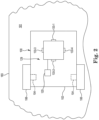
- FIG. 1 schematically illustrates an exemplary autonomous working machine configured as an autonomous lawn mower 100 (also referred to herein as “machine” or “robot”), which forms part of a lawn mowing system 101 that may include other components such as a charging station 50.
- the mower 100 may include a housing 102 (e.g., frame or chassis with a shroud) that carries and/or encloses various components of the mower as described below.
- the mower 100 may further include ground support members, such as wheels, rollers, skids, or tracks.
- the ground support members include one or more rear wheels 106 and one or more front wheels 108, that support the housing 102 upon (and in rolling engagement with) the ground (e.g., turf) surface 103 of the work region.
- the front wheels 108 support at least a front-end portion 134 of the housing 102 and the rear wheels 106 support at least a rear-end portion 136 of the mower housing.
- One or both rear wheels 106 may form drive wheels coupled to and driven by a propulsion system (e.g., including one or more wheel motors 104) to propel the mower 100 over the ground surface 103.
- a propulsion system e.g., including one or more wheel motors 104
- the front wheels 108 may freely caster relative to the housing 102 (e.g., about vertical axes).
- mower direction may be controlled via differential rotation of the two rear wheels 106 in a manner similar to a conventional zero-turn-radius (ZTR) riding mower.
- the propulsion system may include a separate wheel motor 104 for each of a left and right rear wheel 106 (see FIG. 2 ) so that a rotational speed and direction of each rear (drive) wheel may be independently controlled by the propulsion system.
- the front wheels 108 could be actively steerable by the propulsion system (e.g., including one or more steer motors 105) to assist with control of mower 100 direction, and/or could be driven by the propulsion system (i.e., to provide a front-wheel or all-wheel drive mower).
- the propulsion system e.g., including one or more steer motors 105
- the propulsion system i.e., to provide a front-wheel or all-wheel drive mower.
- a ground maintenance implement or tool e.g., a grass cutting element, such as a blade 110
- an implement e.g., cutting
- the mower 100 may be propelled over the ground surface 103 such that vegetation (e.g., grass) over which the mower passes is cut by the rotating blade 110.
- vegetation e.g., grass
- the mower 100 may further include a power source, which in one embodiment, is a battery 114 having a lithium-based chemistry (e.g., lithium-ion).
- a battery 114 having a lithium-based chemistry (e.g., lithium-ion).
- Other embodiments may utilize batteries of other chemistries, or other power source technologies (e.g., solar power, fuel cell, internal combustion engines) altogether, without departing from the scope of this disclosure.
- a power source which in one embodiment, is a battery 114 having a lithium-based chemistry (e.g., lithium-ion).
- Other embodiments may utilize batteries of other chemistries, or other power source technologies (e.g., solar power, fuel cell, internal combustion engines) altogether, without departing from the scope of this disclosure.
- power source e.g., solar power, fuel cell, internal combustion engines
- the mower 100 may further include one or more sensors to provide location data.
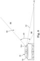
- some embodiments may include a Global Navigational Satellite System (GNSS, e.g., global positioning system or "GPS") receiver 116 (or other position sensor that may provide similar data).
- GNSS Global Navigational Satellite System
- GPS global positioning system
- the GNSS receiver 116 may be adapted to estimate a position of the mower 100 within the work region and provide such information to an electronic controller 120 (described below) associated with the working machine (mower 100).
- the controller is adapted to autonomously control navigation of the machine as the machine traverses the property/work region defined by the property boundary(s).
- one or more of the wheels 106, 108 may include encoders 118 that provide wheel rotation/speed information (odometry) that may be used to estimate mower position (e.g., based upon an initial start position) within a given work region.
- the mower 100 may optionally include a sensor 115 adapted to detect a boundary wire, which could be used in addition to other non-vision-based or vision-based navigational techniques.
- Other sensors such as an inertial measurement unit (IMU) 111, may also be included to assist with machine navigation.
- IMU inertial measurement unit
- An IMU is an electronic device that is capable of measuring and outputting the angular rate, mass-specific force (acceleration) and, optionally, the orientation of a body in space.
- the mower 100 may optionally include one or more front obstacle detection (“bump”) sensors 130 and one or more rear obstacle detection sensors 132, as well as other sensors, such as side obstacle detection sensors (not shown).
- the obstacle detection sensors 130, 132 may be used to detect an obstacle in the path of the mower 100 when travelling in a forward or reverse direction, respectively (the mower 100 may be capable of mowing while moving in both forward and reverse directions).
- the sensors 130, 132 may be located at the front-end portion 134 and rear-end portion 136 of the mower 100, respectively.
- other sensors now known or later developed may also be incorporated into the mower 100.
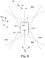
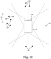
- a partial overhead plan view of 3DPC data e.g., a two-dimensional overhead map of the 3DPC (features 700) for a particular position of the mower 100 within the work region 181, is illustrated.
- the vision system may overlay the relevant horizontal FOVs for each of the cameras 133, wherein: FOV 604-1 corresponds to the horizontal FOV of front-facing camera 133-1; FOV 604-2 corresponds to the horizontal FOV of rear-facing camera 133-2; FOV 604-3 corresponds to the horizontal FOV of left-facing camera 133-3; and FOV 604-4 corresponds to the horizontal FOV of right -facing camera 133-4.
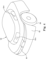
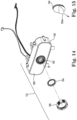
- the lens covering 184 may form a transparent disk incorporating a hydrophilic coating. Hydrophilic coatings were found to perform well in foggy environments. Hydrophobic coatings were also found to provide similar performance benefits. In addition or alternatively, the covering 184 may provide one or more of anti-reflective, anti-glare, and polarizing properties.
Landscapes
- Engineering & Computer Science (AREA)
- Physics & Mathematics (AREA)
- General Physics & Mathematics (AREA)
- Multimedia (AREA)
- Theoretical Computer Science (AREA)
- Computer Vision & Pattern Recognition (AREA)
- Electromagnetism (AREA)
- Environmental Sciences (AREA)
- Life Sciences & Earth Sciences (AREA)
- Aviation & Aerospace Engineering (AREA)
- Radar, Positioning & Navigation (AREA)
- Remote Sensing (AREA)
- Automation & Control Theory (AREA)
- Control Of Position, Course, Altitude, Or Attitude Of Moving Bodies (AREA)
- Guiding Agricultural Machines (AREA)
- Harvester Elements (AREA)
- Navigation (AREA)
Applications Claiming Priority (3)
| Application Number | Priority Date | Filing Date | Title |
|---|---|---|---|
| US202063047423P | 2020-07-02 | 2020-07-02 | |
| EP21742631.1A EP4175455B1 (de) | 2020-07-02 | 2021-06-23 | Autonome maschine mit sichtsystem zur navigation und verfahren zur verwendung davon |
| PCT/US2021/038663 WO2022005840A1 (en) | 2020-07-02 | 2021-06-23 | Autonomous machine having vision system for navigation and method of using same |
Related Parent Applications (2)
| Application Number | Title | Priority Date | Filing Date |
|---|---|---|---|
| EP21742631.1A Division EP4175455B1 (de) | 2020-07-02 | 2021-06-23 | Autonome maschine mit sichtsystem zur navigation und verfahren zur verwendung davon |
| EP21742631.1A Division-Into EP4175455B1 (de) | 2020-07-02 | 2021-06-23 | Autonome maschine mit sichtsystem zur navigation und verfahren zur verwendung davon |
Publications (3)
| Publication Number | Publication Date |
|---|---|
| EP4398202A2 true EP4398202A2 (de) | 2024-07-10 |
| EP4398202A3 EP4398202A3 (de) | 2024-10-16 |
| EP4398202B1 EP4398202B1 (de) | 2026-04-01 |
Family
ID=76943154
Family Applications (2)
| Application Number | Title | Priority Date | Filing Date |
|---|---|---|---|
| EP24169983.4A Active EP4398202B1 (de) | 2020-07-02 | 2021-06-23 | Eine autonome bodenreinigungsmaschine mit einem bildsystem zur navigation und ein verfahren zur autonomen maschinennavigation |
| EP21742631.1A Active EP4175455B1 (de) | 2020-07-02 | 2021-06-23 | Autonome maschine mit sichtsystem zur navigation und verfahren zur verwendung davon |
Family Applications After (1)
| Application Number | Title | Priority Date | Filing Date |
|---|---|---|---|
| EP21742631.1A Active EP4175455B1 (de) | 2020-07-02 | 2021-06-23 | Autonome maschine mit sichtsystem zur navigation und verfahren zur verwendung davon |
Country Status (4)
| Country | Link |
|---|---|
| US (1) | US12593748B2 (de) |
| EP (2) | EP4398202B1 (de) |
| AU (1) | AU2021301131B2 (de) |
| WO (1) | WO2022005840A1 (de) |
Families Citing this family (3)
| Publication number | Priority date | Publication date | Assignee | Title |
|---|---|---|---|---|
| EP4398202B1 (de) | 2020-07-02 | 2026-04-01 | The Toro Company | Eine autonome bodenreinigungsmaschine mit einem bildsystem zur navigation und ein verfahren zur autonomen maschinennavigation |
| US20260099943A1 (en) * | 2022-11-30 | 2026-04-09 | Qualcomm Incorporated | Dynamic camera selection and switching for multi-camera pose estimation |
| US12429875B2 (en) | 2023-04-25 | 2025-09-30 | Textron Innovations Inc. | Providing autonomous mower control via geofencing |
Citations (1)
| Publication number | Priority date | Publication date | Assignee | Title |
|---|---|---|---|---|
| WO2020033522A2 (en) | 2018-08-08 | 2020-02-13 | The Toro Company | Handle and method for training an autonomous vehicle, and methods of storing same |
Family Cites Families (10)
| Publication number | Priority date | Publication date | Assignee | Title |
|---|---|---|---|---|
| EP2199983A1 (de) | 2008-12-22 | 2010-06-23 | Nederlandse Centrale Organisatie Voor Toegepast Natuurwetenschappelijk Onderzoek TNO | Verfahren zur Schätzung einer Bewegung eines Systems mit mehreren Kameras, System mit mehreren Kameras und Computerprogrammprodukt |
| EP3118815B1 (de) | 2009-07-01 | 2018-03-07 | MTD Products Inc. | Visuelle segmentierung von rasengras |
| EP2620050B1 (de) | 2012-01-25 | 2016-07-27 | Honda Research Institute Europe GmbH | System, Verfahren und Vorrichtung zur unbeaufsichtigten Anpassung der Wahrnehmung eines automatischen Mähers |
| EP2884364B1 (de) * | 2013-12-12 | 2018-09-26 | Hexagon Technology Center GmbH | Autonomes Gartenarbeitsfahrzeug mit Kamera |
| US9751210B2 (en) * | 2014-11-26 | 2017-09-05 | Irobot Corporation | Systems and methods for performing occlusion detection |
| EP3232763A1 (de) | 2014-12-17 | 2017-10-25 | Husqvarna AB | Roboterfahrzeug mit automatischer kamerakalibrierung |
| EP4235596A3 (de) | 2014-12-22 | 2023-10-04 | Husqvarna AB | Grasstrukturdetektion durch ein robotisches fahrzeug |
| US9442306B1 (en) | 2015-08-17 | 2016-09-13 | Ripclear Llc | Lens protection systems |
| CN108369420B (zh) | 2015-11-02 | 2021-11-05 | 星船科技私人有限公司 | 用于自主定位的设备和方法 |
| EP4398202B1 (de) | 2020-07-02 | 2026-04-01 | The Toro Company | Eine autonome bodenreinigungsmaschine mit einem bildsystem zur navigation und ein verfahren zur autonomen maschinennavigation |
-
2021
- 2021-06-23 EP EP24169983.4A patent/EP4398202B1/de active Active
- 2021-06-23 AU AU2021301131A patent/AU2021301131B2/en active Active
- 2021-06-23 EP EP21742631.1A patent/EP4175455B1/de active Active
- 2021-06-23 WO PCT/US2021/038663 patent/WO2022005840A1/en not_active Ceased
- 2021-06-23 US US18/011,259 patent/US12593748B2/en active Active
Patent Citations (2)
| Publication number | Priority date | Publication date | Assignee | Title |
|---|---|---|---|---|
| WO2020033522A2 (en) | 2018-08-08 | 2020-02-13 | The Toro Company | Handle and method for training an autonomous vehicle, and methods of storing same |
| US20200050208A1 (en) | 2018-08-08 | 2020-02-13 | The Toro Company | Autonomous machine navigation and training using vision system |
Also Published As
| Publication number | Publication date |
|---|---|
| US12593748B2 (en) | 2026-04-07 |
| EP4175455A1 (de) | 2023-05-10 |
| EP4398202B1 (de) | 2026-04-01 |
| AU2021301131A1 (en) | 2023-02-09 |
| EP4398202A3 (de) | 2024-10-16 |
| EP4175455B1 (de) | 2024-07-24 |
| AU2021301131B2 (en) | 2026-04-16 |
| US20230225241A1 (en) | 2023-07-20 |
| WO2022005840A1 (en) | 2022-01-06 |
Similar Documents
| Publication | Publication Date | Title |
|---|---|---|
| AU2024220020B2 (en) | Autonomous machine navigation and training using vision system | |
| US20250172940A1 (en) | Autonomous machine navigation with object detection and 3d point cloud | |
| US20230236604A1 (en) | Autonomous machine navigation using reflections from subsurface objects | |
| EP4398202B1 (de) | Eine autonome bodenreinigungsmaschine mit einem bildsystem zur navigation und ein verfahren zur autonomen maschinennavigation | |
| AU2020271875B2 (en) | Autonomous machine navigation in lowlight conditions | |
| EP4066076B1 (de) | Autonome maschinennavigation in verschiedenen beleuchtungsumgebungen | |
| AU2025202548B2 (en) | Autonomous Machine Navigation in Lowlight Conditions | |
| AU2024221405A1 (en) | Image notification for autonomous grounds maintenance machines |
Legal Events
| Date | Code | Title | Description |
|---|---|---|---|
| PUAI | Public reference made under article 153(3) epc to a published international application that has entered the european phase |
Free format text: ORIGINAL CODE: 0009012 |
|
| STAA | Information on the status of an ep patent application or granted ep patent |
Free format text: STATUS: THE APPLICATION HAS BEEN PUBLISHED |
|
| AC | Divisional application: reference to earlier application |
Ref document number: 4175455 Country of ref document: EP Kind code of ref document: P |
|
| AK | Designated contracting states |
Kind code of ref document: A2 Designated state(s): AL AT BE BG CH CY CZ DE DK EE ES FI FR GB GR HR HU IE IS IT LI LT LU LV MC MK MT NL NO PL PT RO RS SE SI SK SM TR |
|
| REG | Reference to a national code |
Ref country code: DE Free format text: PREVIOUS MAIN CLASS: G06V0020640000 Ref legal event code: R079 Ref document number: 602021051454 Country of ref document: DE Ipc: A01D0034000000 |
|
| PUAL | Search report despatched |
Free format text: ORIGINAL CODE: 0009013 |
|
| AK | Designated contracting states |
Kind code of ref document: A3 Designated state(s): AL AT BE BG CH CY CZ DE DK EE ES FI FR GB GR HR HU IE IS IT LI LT LU LV MC MK MT NL NO PL PT RO RS SE SI SK SM TR |
|
| RIC1 | Information provided on ipc code assigned before grant |
Ipc: A01D 34/00 20060101AFI20240910BHEP |
|
| STAA | Information on the status of an ep patent application or granted ep patent |
Free format text: STATUS: REQUEST FOR EXAMINATION WAS MADE |
|
| 17P | Request for examination filed |
Effective date: 20250213 |
|
| GRAP | Despatch of communication of intention to grant a patent |
Free format text: ORIGINAL CODE: EPIDOSNIGR1 |
|
| STAA | Information on the status of an ep patent application or granted ep patent |
Free format text: STATUS: GRANT OF PATENT IS INTENDED |
|
| INTG | Intention to grant announced |
Effective date: 20251124 |
|
| GRAS | Grant fee paid |
Free format text: ORIGINAL CODE: EPIDOSNIGR3 |
|
| GRAA | (expected) grant |
Free format text: ORIGINAL CODE: 0009210 |
|
| STAA | Information on the status of an ep patent application or granted ep patent |
Free format text: STATUS: THE PATENT HAS BEEN GRANTED |
|
| P01 | Opt-out of the competence of the unified patent court (upc) registered |
Free format text: CASE NUMBER: UPC_APP_0004124_4398202/2026 Effective date: 20260204 |
|
| AC | Divisional application: reference to earlier application |
Ref document number: 4175455 Country of ref document: EP Kind code of ref document: P |
|
| AK | Designated contracting states |
Kind code of ref document: B1 Designated state(s): AL AT BE BG CH CY CZ DE DK EE ES FI FR GB GR HR HU IE IS IT LI LT LU LV MC MK MT NL NO PL PT RO RS SE SI SK SM TR |
|
| REG | Reference to a national code |
Ref country code: CH Ref legal event code: F10 Free format text: ST27 STATUS EVENT CODE: U-0-0-F10-F00 (AS PROVIDED BY THE NATIONAL OFFICE) Effective date: 20260401 Ref country code: GB Ref legal event code: FG4D |
|
| REG | Reference to a national code |
Ref country code: IE Ref legal event code: FG4D |
|
| REG | Reference to a national code |
Ref country code: DE Ref legal event code: R096 Ref document number: 602021051454 Country of ref document: DE |