EP4398211A1 - Unterhaltungsmaschine - Google Patents
Unterhaltungsmaschine Download PDFInfo
- Publication number
- EP4398211A1 EP4398211A1 EP24150559.3A EP24150559A EP4398211A1 EP 4398211 A1 EP4398211 A1 EP 4398211A1 EP 24150559 A EP24150559 A EP 24150559A EP 4398211 A1 EP4398211 A1 EP 4398211A1
- Authority
- EP
- European Patent Office
- Prior art keywords
- carousel
- ball
- entertainment machine
- operable
- balls
- Prior art date
- Legal status (The legal status is an assumption and is not a legal conclusion. Google has not performed a legal analysis and makes no representation as to the accuracy of the status listed.)
- Withdrawn
Links
Images


Classifications
-
- G—PHYSICS
- G07—CHECKING-DEVICES
- G07F—COIN-FREED OR LIKE APPARATUS
- G07F17/00—Coin-freed apparatus for hiring articles; Coin-freed facilities or services
- G07F17/32—Coin-freed apparatus for hiring articles; Coin-freed facilities or services for games, toys, sports, or amusements
- G07F17/38—Ball games; Shooting apparatus
-
- A—HUMAN NECESSITIES
- A63—SPORTS; GAMES; AMUSEMENTS
- A63F—CARD, BOARD, OR ROULETTE GAMES; INDOOR GAMES USING SMALL MOVING PLAYING BODIES; VIDEO GAMES; GAMES NOT OTHERWISE PROVIDED FOR
- A63F5/00—Roulette games
- A63F5/02—Roulette-like ball games
-
- G—PHYSICS
- G07—CHECKING-DEVICES
- G07F—COIN-FREED OR LIKE APPARATUS
- G07F17/00—Coin-freed apparatus for hiring articles; Coin-freed facilities or services
- G07F17/32—Coin-freed apparatus for hiring articles; Coin-freed facilities or services for games, toys, sports, or amusements
- G07F17/3202—Hardware aspects of a gaming system, e.g. components, construction, architecture thereof
- G07F17/3204—Player-machine interfaces
- G07F17/3211—Display means
- G07F17/3213—Details of moving display elements, e.g. spinning reels, tumbling members
-
- G—PHYSICS
- G07—CHECKING-DEVICES
- G07F—COIN-FREED OR LIKE APPARATUS
- G07F17/00—Coin-freed apparatus for hiring articles; Coin-freed facilities or services
- G07F17/32—Coin-freed apparatus for hiring articles; Coin-freed facilities or services for games, toys, sports, or amusements
- G07F17/3286—Type of games
- G07F17/3297—Fairground games, e.g. Tivoli, coin pusher machines, cranes
-
- G—PHYSICS
- G07—CHECKING-DEVICES
- G07F—COIN-FREED OR LIKE APPARATUS
- G07F17/00—Coin-freed apparatus for hiring articles; Coin-freed facilities or services
- G07F17/32—Coin-freed apparatus for hiring articles; Coin-freed facilities or services for games, toys, sports, or amusements
- G07F17/34—Coin-freed apparatus for hiring articles; Coin-freed facilities or services for games, toys, sports, or amusements depending on the stopping of moving members in a mechanical slot machine, e.g. "fruit" machines
Definitions
- the entertainment machine may comprise a control unit.
- the control unit may comprise a microprocessor.
- the control unit may be operable in response to the sensor arrangement to determine, based on the carousel orientation, that a token, in the form of a ball was received in a particular receiving hole.
- the control unit may be operable to thereby award prize value.
- the awarded prize value may be the same for each receiving hole.
- the awarded prize value may vary for different receiving holes.
- the prize value of each receiving hole may be marked on the upper surface of the carousel in the vicinity of each receiving hole.
- the carousel may be provided with a co-rotating base plate.
- the base plate may be fitted to the lower surface of the carousel.
- the base plate may be provided on a common axle or a common rotation axis to the carousel.
- the base plate may be provided below the platform.
- the base plate may comprise a disc having a toothed outer edge.
- teeth or gaps between teeth may be aligned with the receiving holes.
- each tooth or gap may be aligned with a receiving hole.
- only some teeth or holes are aligned with a receiving hole. This arrangement beneficially allows for variable receiving hole spacing.
- the carousel orientation sensor may be operable to detect the teeth. By maintaining a running count of the detected teeth carousel orientation can be determined.
- the upper surface of the carousel may comprise a central projecting boss.
- the boss may be aligned with the rotational axis of the carousel.
- the boss may have a substantially dome like form. Beneficially, this causes the boss to direct incident balls outwardly towards the receiving holes of the carousel.
- the sensor arrangement may additionally comprise an origin reference sensor.
- the origin reference sensor may be operable to detect a reference marker to determine a reference or origin orientation of the carousel.
- the reference maker may be fitted to the base plate at a refence location.
- the origin reference sensor can be used to reset the running count of the carousel teeth.
- the origin reference sensor may be an optical sensor, infrared sensor, magnetic sensor, camera or radio frequency identification (RFID) sensor as appropriate.
- the origin reference sensor may be an optical or infrared sensor comprising an emitting element operable to output a beam and a receiving element operable to detect the emitted beam. In such embodiments, interruption of the beam by the reference marker may be detected to determine orientation.
- the funnel may be formed from a substantially transparent material. This is beneficial since it allows a user to view the carousel through the funnel.
- the machine may be provided with an entry chute through which a ball is introduced into a playing zone.
- the entry chute may comprise an elongate sloped passage.
- the entry chute may comprise a substantially liner passage or a curved passage.
- the entry chute may slope down to an exit end.
- the entry chute may be an enclosed or partially enclosed passage. In some embodiments, the entry chute is only partially enclosed at the exit end.
- the balls may be formed from a substantially spherical plastic shell with a hollow interior.
- the balls may all be the same size. In other embodiments, the balls be of two, three or more different sizes.
- the balls may all be the same colour and/or have the same surface decoration. In other embodiments, different balls may have different colours and/or surface decoration. If the difference in colour/surface decoration can be detected by the sensor arrangement, the difference can be used to calculate prize value.
- balls may comprise an implanted RFID device. If the ball drop sensor is operable to detect an embedded RFID device this can be used to calculate prize value.
- Tokens dropping through the exit slot may pass to a collection hopper.
- balls may drop directly into said collection hopper.
- balls may pass to the collection hopper through an exit chute.
- a collection chute may be provided around all or part of the outside of the carousel.
- the collection chute may receive balls that are not received in the receiving holes.
- the collection chute may direct balls to the collection hopper.
- each collection hopper may have a separate lift module.
- separate entry chutes may be provided for each lift module. This can allow for balls to be introduced from different chutes so as to increase player engagement and excitement.
- the entertainment machine may be provided with a credit input device.
- the credit input device may be operable to receive user credit input and output a credit signal in response thereto.
- the credit unit may comprise a coin reader, note reader, card reader, barcode reader, QR code reader or ticket reader as appropriate.
- the entertainment machine may be provided with a prize output device.
- the prize output device may be operable in response to the control unit to enable output of prize value to a user.
- the prize output device may be a coin dispenser, note dispenser, ticket printer or other printer as appropriate.
- the entertainment machine may be provided with a prize value display unit.
- the prize value display unit may be operable in response to the control unit to display a value indicative of current user prize value.
- the current user prize value may be calculated by the control unit in response to the machine operation. In particular, this may be calculated in response to detection of balls dropping from receiving holes.
- the current user prize value may include prize value awarded by the bonus game.
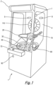
- the ball 3 rolls across the surface of the funnel 20 until it drops through an aperture 21 at the base of the funnel 20.
- the ball 3 subsequently interacts with and moves across the upper surface 32 of carousel 30 until it comes to rest in a receiving hole 31.
- the control unit 100 is operable to control a credit display 8 to display a current sum of user credits.
- the control unit 100 is operable to control a motor 120 (typically mounted below platform 40) to rotate the carousel 30.
- the carousel 30 might be rotated at a pre-set fixed rate in most embodiments, but the skilled person will appreciate that in other examples, the control unit may be operable to control motor 120 to vary the carousel 30 rotation rate.
- the ball dispensing mechanism 12 can be set to automatically dispense balls 3 until no further credit remains.
- the dispensed balls 3 can be dispensed singly at regular intervals or in groups of two or more, at regular intervals or when a previous ball 3 drops through exit slot 41.
- control unit 100 may be operable to cause the ball dispensing mechanism 12 to dispense one or more balls 3 in response to detection of user input via a user actable input means 70.
- the user actuable input means may comprise any suitable element including but not limited to buttons, switches, key pads, pointing devices, touch sensitive panels or displays.
- the sensor arrangement 20 comprises a ball drop sensor 51 operable to output a signal when a ball dropping through the exit slot 41 is detected.
- an orientation sensor 52 outputs a signal indicative of the carousel 30 orientation when the ball drop is detected.
- the sensing arrangement 50 additionally comprises an origin reference sensor 53 operable to detect a reference marker 34 on the carousel 30. This can be used to calibrate and/or rest the orientation sensor 52, if necessary.
- the ball drop sensor 51, orientation sensor 52 and optional origin reference sensor 53 may comprise any suitable form of sensor including but not limited to optical sensors, infrared sensors, magnetic sensors, cameras or radio frequency identification (RFID) sensors as appropriate.
- RFID radio frequency identification
- the control unit 100 When the user credit is exhausted, the control unit 100 is operable to activate a prize output device 90 to enable output of any positive non-zero prize value to a user.
- the prize output device 90 may be of any suitable form known in the art.
- the prize output device 90 may comprise a coin/note dispenser, ticket printer or other device as appropriate.
- the entry chute 10 is offset from the aperture 21 of funnel 20. This causes balls 3 to have a significant tangential velocity component relative to the aperture 21 when dropped on to funnel 20. This causes balls 3 to roll around the surface of the funnel 20 rather than dropping straight through the aperture 21, thereby increasing user engagement and excitement.
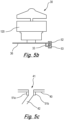
- the funnel 20 is substantially conical with an upper rim 22.
- the rim 22 is attached to a bracket 23.
- the bracket 23 is mounted on a back panel 4 of the entertainment machine.
- the bonus game 110 can able be provided on the back panel 4.
- the funnel 20 is substantially transparent which enables users to see the carousel through the funnel.
- the carousel 30 has an upper surface 39 comprising a bulbous boss 38 aligned with the rotation axis.
- the boss 38 thus helps deflect balls 3 dropping from the funnel 20 towards the receiving holes 31.
- each sector 37 is marked with an associated prise value (or bonus feature start indicia).
- each sector 37 contains a single receiving hole 31.
- sectors 37 may be provided with multiple receiving holes 31.
- the surface of each sector 37 may optionally be shaped to help direct balls 3 to the receiving hole 31.
- a fixed outer wall 60 fits around the carousel 30.
- the outer wall 60 blocks balls 3 from rolling off the outer edge of the carousel 30.
- the receiving holes 31 are sufficiently close to the outer edge of the carousel 30 that a ball 3 in contact with the outer wall 60 will fall into a receiving hole 31 as the carousel 30 rotates.
- a brush rod 65 projects from the outer wall 60. This brush rod 65 is angled so as to urge any balls 3 not securely received in a receiving hole 31 into said receiving hole as it rotates past. In this instance, the brush rod 65 is located over the exit slot 41 so that it further helps balls 3 to drop through the receiving hole 31 and exit slot 41 as the carousel rotates past the brush rod.
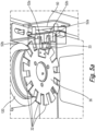
- the carousel 30 is additionally provided with a base plate 36.
- the base plate 36 is fitted about a common rotation axis to the carousel 36 so as to rotate at the same rate as the carousel 30.
- this base plate 36 is provided on the opposite side of motor 120 to the carousel 30 and below platform 40.
- the base plate 36 could be provided in other locations such as directly mounted to the lower surface of carousel 30.
- the fixing plate 36 is provided with a series of teeth 32 around its outer edge.
- the teeth 32 are regularly spaced and each receiving hole 31 is aligned with a particular tooth 32 or gap between successive teeth 32.
- the exemplary orientation sensor 52 comprises an optical emitting element 52a operable to output a light beam and an optical receiving element 52b operable to detect the emitted beam. Successive interruptions of the beam by passage of the teeth 32 between the elements 52a, 52b are detected as carousel 30 rotates. Since the number of teeth 32 on the base plate 36 is known, maintaining a running count of the detected teeth 32 enables the orientation of the carousel to be determined. In the exemplary implementation, the orientation sensor will output a signal in response to each interruption of the emitted beam to the control unit 100. This would then allow the control unit to maintain the count and determine carousel orientation from the maintained count.
- the fixing plate 36 is additionally provided with a reference marker 33 in the form of a projecting finger.
- the exemplary origin reference sensor 53 in this figure comprises an optical emitting element 53a operable to output a light beam and an optical receiving element 53b operable to detect the emitted beam. Passage of the refence marker 33 is detected by interruption of the beam between sensing elements 53a, 53b. When the reference marker 33 is detected, the origin reference sensor 53 can output an indicative signal to the control unit. As the reference marker 33 is provided at only one location on the base plate 36, this provides origin calibration for the count of the orientation sensor 52.
Landscapes
- Physics & Mathematics (AREA)
- General Physics & Mathematics (AREA)
- Engineering & Computer Science (AREA)
- Multimedia (AREA)
- Pinball Game Machines (AREA)
- Vending Machines For Individual Products (AREA)
Applications Claiming Priority (1)
| Application Number | Priority Date | Filing Date | Title |
|---|---|---|---|
| GB2300263.7A GB2626034A (en) | 2023-01-09 | 2023-01-09 | Entertainment Machine |
Publications (1)
| Publication Number | Publication Date |
|---|---|
| EP4398211A1 true EP4398211A1 (de) | 2024-07-10 |
Family
ID=89508904
Family Applications (1)
| Application Number | Title | Priority Date | Filing Date |
|---|---|---|---|
| EP24150559.3A Withdrawn EP4398211A1 (de) | 2023-01-09 | 2024-01-05 | Unterhaltungsmaschine |
Country Status (2)
| Country | Link |
|---|---|
| EP (1) | EP4398211A1 (de) |
| GB (1) | GB2626034A (de) |
Citations (6)
| Publication number | Priority date | Publication date | Assignee | Title |
|---|---|---|---|---|
| GB2284499A (en) * | 1993-12-03 | 1995-06-07 | Mcnally Gaming Limited | Gaming machines |
| US20060019735A1 (en) * | 2002-09-17 | 2006-01-26 | Hirobumi Toyoda | Game machine and program |
| US20070057451A1 (en) * | 2005-09-02 | 2007-03-15 | Benchmark Entertainment L.C. | Ball drop amusement game |
| US20080280661A1 (en) * | 2007-05-10 | 2008-11-13 | Shoemaker Jr Stephen P | Projectile roulette arcade game |
| US20090061979A1 (en) * | 2006-02-13 | 2009-03-05 | Konami Digital Entertainment Co., Ltd. | Gaming device and its control method |
| US10453313B2 (en) * | 2016-03-23 | 2019-10-22 | ACME Game Designs LLC | Parabolic ball launcher amusement game |
Family Cites Families (1)
| Publication number | Priority date | Publication date | Assignee | Title |
|---|---|---|---|---|
| JP4528646B2 (ja) * | 2005-02-14 | 2010-08-18 | 株式会社カプコン | 抽選装置 |
-
2023
- 2023-01-09 GB GB2300263.7A patent/GB2626034A/en active Pending
-
2024
- 2024-01-05 EP EP24150559.3A patent/EP4398211A1/de not_active Withdrawn
Patent Citations (6)
| Publication number | Priority date | Publication date | Assignee | Title |
|---|---|---|---|---|
| GB2284499A (en) * | 1993-12-03 | 1995-06-07 | Mcnally Gaming Limited | Gaming machines |
| US20060019735A1 (en) * | 2002-09-17 | 2006-01-26 | Hirobumi Toyoda | Game machine and program |
| US20070057451A1 (en) * | 2005-09-02 | 2007-03-15 | Benchmark Entertainment L.C. | Ball drop amusement game |
| US20090061979A1 (en) * | 2006-02-13 | 2009-03-05 | Konami Digital Entertainment Co., Ltd. | Gaming device and its control method |
| US20080280661A1 (en) * | 2007-05-10 | 2008-11-13 | Shoemaker Jr Stephen P | Projectile roulette arcade game |
| US10453313B2 (en) * | 2016-03-23 | 2019-10-22 | ACME Game Designs LLC | Parabolic ball launcher amusement game |
Also Published As
| Publication number | Publication date |
|---|---|
| GB2626034A (en) | 2024-07-10 |
Similar Documents
| Publication | Publication Date | Title |
|---|---|---|
| US4869505A (en) | Roulette playing device | |
| US7815187B2 (en) | Roulette board and method for controlling the same | |
| US6899328B2 (en) | Amusement game | |
| EP0267804A2 (de) | Vorrichtung zum Roulettespielen | |
| US8448948B1 (en) | Vertically arranged arcade game | |
| CN102223928B (zh) | 物理抽签装置和具有该物理抽签装置的游戏装置 | |
| US4441515A (en) | Gaming device including coin dispensing means | |
| NZ214737A (en) | Ball return mechanism for roulette wheel | |
| CN102223929B (zh) | 物理抽签装置和具有该物理抽签装置的游戏装置 | |
| US7507152B2 (en) | Ball drop amusement game | |
| CN102223930A (zh) | 物理抽签装置和具有该物理抽签装置的游戏装置 | |
| US20030155367A1 (en) | Optical device for detecting a falling object | |
| WO1995024952A1 (en) | Coin operated amusement device | |
| US20060068878A1 (en) | Roulette revenue method and apparatus | |
| JP4658079B2 (ja) | メダルゲーム機 | |
| EP0615775A2 (de) | Spielvorrichtungen und Maschinen | |
| GB2626034A (en) | Entertainment Machine | |
| US6991230B1 (en) | Revolving target amusement apparatus | |
| WO2006094398A1 (en) | Methods and systems for applying additional randomness in a roulette environment | |
| US7559552B2 (en) | Coin roulette arcade game | |
| GB2284499A (en) | Gaming machines | |
| US8568214B1 (en) | Arcade game with rotating and counter rotating pointer and turntable | |
| WO1987006042A1 (en) | Games apparatus | |
| JP2006527876A (ja) | コイン払出装置 | |
| JP2005287951A (ja) | 遊技機 |
Legal Events
| Date | Code | Title | Description |
|---|---|---|---|
| PUAI | Public reference made under article 153(3) epc to a published international application that has entered the european phase |
Free format text: ORIGINAL CODE: 0009012 |
|
| STAA | Information on the status of an ep patent application or granted ep patent |
Free format text: STATUS: THE APPLICATION HAS BEEN PUBLISHED |
|
| AK | Designated contracting states |
Kind code of ref document: A1 Designated state(s): AL AT BE BG CH CY CZ DE DK EE ES FI FR GB GR HR HU IE IS IT LI LT LU LV MC ME MK MT NL NO PL PT RO RS SE SI SK SM TR |
|
| STAA | Information on the status of an ep patent application or granted ep patent |
Free format text: STATUS: THE APPLICATION IS DEEMED TO BE WITHDRAWN |
|
| 18D | Application deemed to be withdrawn |
Effective date: 20250111 |