EP4398261A1 - Système, dispositif, programme et procédé d'évaluation de capacités stéréognostiques - Google Patents
Système, dispositif, programme et procédé d'évaluation de capacités stéréognostiques Download PDFInfo
- Publication number
- EP4398261A1 EP4398261A1 EP22864390.4A EP22864390A EP4398261A1 EP 4398261 A1 EP4398261 A1 EP 4398261A1 EP 22864390 A EP22864390 A EP 22864390A EP 4398261 A1 EP4398261 A1 EP 4398261A1
- Authority
- EP
- European Patent Office
- Prior art keywords
- stereognostic
- moving object
- ability
- feature value
- subject
- Prior art date
- Legal status (The legal status is an assumption and is not a legal conclusion. Google has not performed a legal analysis and makes no representation as to the accuracy of the status listed.)
- Pending
Links
Images


Classifications
-
- G—PHYSICS
- G16—INFORMATION AND COMMUNICATION TECHNOLOGY [ICT] SPECIALLY ADAPTED FOR SPECIFIC APPLICATION FIELDS
- G16H—HEALTHCARE INFORMATICS, i.e. INFORMATION AND COMMUNICATION TECHNOLOGY [ICT] SPECIALLY ADAPTED FOR THE HANDLING OR PROCESSING OF MEDICAL OR HEALTHCARE DATA
- G16H50/00—ICT specially adapted for medical diagnosis, medical simulation or medical data mining; ICT specially adapted for detecting, monitoring or modelling epidemics or pandemics
- G16H50/30—ICT specially adapted for medical diagnosis, medical simulation or medical data mining; ICT specially adapted for detecting, monitoring or modelling epidemics or pandemics for calculating health indices; for individual health risk assessment
-
- G—PHYSICS
- G01—MEASURING; TESTING
- G01B—MEASURING LENGTH, THICKNESS OR SIMILAR LINEAR DIMENSIONS; MEASURING ANGLES; MEASURING AREAS; MEASURING IRREGULARITIES OF SURFACES OR CONTOURS
- G01B21/00—Measuring arrangements or details thereof, where the measuring technique is not covered by the other groups of this subclass, unspecified or not relevant
-
- A—HUMAN NECESSITIES
- A61—MEDICAL OR VETERINARY SCIENCE; HYGIENE
- A61B—DIAGNOSIS; SURGERY; IDENTIFICATION
- A61B3/00—Apparatus for testing the eyes; Instruments for examining the eyes
- A61B3/02—Subjective types, i.e. testing apparatus requiring the active assistance of the patient
- A61B3/08—Subjective types, i.e. testing apparatus requiring the active assistance of the patient for testing binocular or stereoscopic vision, e.g. strabismus
-
- A—HUMAN NECESSITIES
- A61—MEDICAL OR VETERINARY SCIENCE; HYGIENE
- A61B—DIAGNOSIS; SURGERY; IDENTIFICATION
- A61B3/00—Apparatus for testing the eyes; Instruments for examining the eyes
- A61B3/10—Objective types, i.e. instruments for examining the eyes independent of the patients' perceptions or reactions
- A61B3/113—Objective types, i.e. instruments for examining the eyes independent of the patients' perceptions or reactions for determining or recording eye movement
-
- G—PHYSICS
- G06—COMPUTING OR CALCULATING; COUNTING
- G06F—ELECTRIC DIGITAL DATA PROCESSING
- G06F3/00—Input arrangements for transferring data to be processed into a form capable of being handled by the computer; Output arrangements for transferring data from processing unit to output unit, e.g. interface arrangements
- G06F3/01—Input arrangements or combined input and output arrangements for interaction between user and computer
- G06F3/011—Arrangements for interaction with the human body, e.g. for user immersion in virtual reality
- G06F3/013—Eye tracking input arrangements
-
- G—PHYSICS
- G06—COMPUTING OR CALCULATING; COUNTING
- G06T—IMAGE DATA PROCESSING OR GENERATION, IN GENERAL
- G06T7/00—Image analysis
- G06T7/70—Determining position or orientation of objects or cameras
-
- G—PHYSICS
- G09—EDUCATION; CRYPTOGRAPHY; DISPLAY; ADVERTISING; SEALS
- G09B—EDUCATIONAL OR DEMONSTRATION APPLIANCES; APPLIANCES FOR TEACHING, OR COMMUNICATING WITH, THE BLIND, DEAF OR MUTE; MODELS; PLANETARIA; GLOBES; MAPS; DIAGRAMS
- G09B9/00—Simulators for teaching or training purposes
- G09B9/02—Simulators for teaching or training purposes for teaching control of vehicles or other craft
- G09B9/04—Simulators for teaching or training purposes for teaching control of vehicles or other craft for teaching control of land vehicles
- G09B9/052—Simulators for teaching or training purposes for teaching control of vehicles or other craft for teaching control of land vehicles characterised by provision for recording or measuring trainee's performance
-
- G—PHYSICS
- G16—INFORMATION AND COMMUNICATION TECHNOLOGY [ICT] SPECIALLY ADAPTED FOR SPECIFIC APPLICATION FIELDS
- G16H—HEALTHCARE INFORMATICS, i.e. INFORMATION AND COMMUNICATION TECHNOLOGY [ICT] SPECIALLY ADAPTED FOR THE HANDLING OR PROCESSING OF MEDICAL OR HEALTHCARE DATA
- G16H50/00—ICT specially adapted for medical diagnosis, medical simulation or medical data mining; ICT specially adapted for detecting, monitoring or modelling epidemics or pandemics
- G16H50/20—ICT specially adapted for medical diagnosis, medical simulation or medical data mining; ICT specially adapted for detecting, monitoring or modelling epidemics or pandemics for computer-aided diagnosis, e.g. based on medical expert systems
-
- A—HUMAN NECESSITIES
- A61—MEDICAL OR VETERINARY SCIENCE; HYGIENE
- A61B—DIAGNOSIS; SURGERY; IDENTIFICATION
- A61B5/00—Measuring for diagnostic purposes; Identification of persons
- A61B5/16—Devices for psychotechnics; Testing reaction times ; Devices for evaluating the psychological state
- A61B5/162—Testing reaction times
-
- G—PHYSICS
- G06—COMPUTING OR CALCULATING; COUNTING
- G06T—IMAGE DATA PROCESSING OR GENERATION, IN GENERAL
- G06T2207/00—Indexing scheme for image analysis or image enhancement
- G06T2207/10—Image acquisition modality
- G06T2207/10016—Video; Image sequence
Definitions
- the present disclosure relates to a stereognostic ability evaluation system, a stereognostic ability evaluation device, a stereognostic ability evaluation program, and a stereognostic ability evaluation method.
- Japanese Patent No. 6000968 discloses a system using a portable touch-screen personal computing device as a system for evaluating a cognitive function using a visual measurement.
- the system performs a cognitive assessment for an individual based on a speed of a response to a displayed stimulus for cognitive assessment.
- a cognitive assessment test a response time from when a character is displayed on a display of the personal computing device to a user's response, or when a button is pressed, is measured.
- Japanese National Patent Publication No. 2015-502238 discloses a system for mapping a peripheral vision of a subject for providing a video game, including a test in which the subject finds a visual stimulus presented for a short period of time.
- the display displays a target, and a glaucomatous visual field defect is measured based on a user's response to the target.
- Stereognostic ability is an ability to recognize whether an object is near or far, and to respond appropriately thereto, and may also be represented for example as perspective.
- the stereognostic ability determination unit determines the stereognostic ability from at least one of a first feature value and a second feature value, the first feature value being derived from a value obtained by differentiating a first distance between a reference object and the moving object with time at least once, the reference object preceding the moving object in a direction in which the moving object travels, the second feature value being relevant to a second distance between a reference line and the moving object, the reference line extending in the direction in which the moving object travels.
- the stereognostic ability determination unit determines the stereognostic ability from at least one of a first feature value and a second feature value, the first feature value being derived from a value obtained by differentiating a first distance between a reference object and the moving object with time at least once, the reference object preceding the moving object in a direction in which the moving object travels, the second feature value being relevant to a second distance between a reference line and the moving object, the reference line extending in the direction in which the moving object travels.
- the housing accommodates the behavior acquisition unit and the stereognostic ability determination unit.
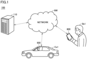
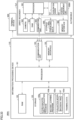
- Fig. 1 is a block diagram showing a configuration of a stereognostic ability evaluation system 100 according to a first embodiment.
- stereognostic ability evaluation system 100 comprises an information processing device 110 (a stereognostic ability evaluation device), a terminal device 800 of a subject Sb1, and a drive recorder 900 (a movement recording device) mounted in an automobile Cs1.
- Information processing device 110, terminal device 800, automobile Cs1, and drive recorder 900 are interconnected via a network NW.
- Network NW includes, for example, the Internet, a LAN (Local Area Network), or a cloud system.
- Subject Sb1 is a subject whose stereognostic ability is measured by stereognostic ability evaluation system 100. Subject Sb1 gets in automobile Cs1 and drives automobile Cs1. Traveling data (or video data) of automobile Cs1 driven by subject Sb1 is recorded by drive recorder 900.
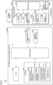
- Processor 101 is processing circuitry for executing a variety of types of functions for controlling an operation of information processing device 110.
- Processor 101 includes a CPU (Central Processing Unit) or a GPU (Graphics Processing Unit) that operates an information device such as a computer.
- CPU Central Processing Unit
- GPU Graphics Processing Unit
- Evaluation model 103c evaluates subject Sb1's stereognostic ability from a feature value derived from the traveling data of subject Sb1.
- Evaluation model 103c may be a classification model that classifies subject Sb1's stereognostic ability into any one of a plurality of predetermined levels, or may be a regression model that outputs a numerical value corresponding to the stereognostic ability.
- Evaluation model 103c is referred to by stereognostic ability evaluation program 103a.
- Evaluation model 103c includes a decision tree DT (Decision Tree).
- Evaluation model 103c may include, for example, a neural network or a support vector machine. Training data 103d is referred to by machine learning program 103b.
- An input/output unit (not shown) that receives an input from a user and displays a processing result of processor 101 to the user may be connected to information processing device 110.
- the input/output unit includes, for example, a display, a touch panel, a keyboard, a speaker, a lamp, and a mouse.
- Drive recorder 900 includes a processor 901, a camera 902, a RAM 903, a communication unit 904, a storage 905, a memory interface 906, and a position measurement unit 907.
- Processor 901, RAM 903, communication unit 904 and memory interface 906 are substantially identical in function to processor 101, RAM 102, communication unit 104 and memory interface 105 of information processing device 110, and accordingly, will not be described in function repeatedly.
- the information about the position of automobile Cs1 includes information that can determine a correspondence between time and automobile Cs1's three-dimensional spatial coordinates, the three-dimensional spatial coordinates of each of at least one reference position, and a reference line in a three-dimensional space.
- stereognostic ability determination unit 101e Based on the information about the position of automobile Cs1, stereognostic ability determination unit 101e derives a feature value derived from at least one of an interval velocity of automobile Cs1, an interval acceleration thereof, a slide amplitude in absolute value thereof, a slide velocity in absolute value thereof, a slide acceleration in absolute value thereof, the slide amplitude, the slide velocity, and the slide acceleration. Stereognostic ability determination unit 101e uses evaluation model 103c to determine subject Sb1's stereognostic ability from the feature value. The information about the reaction received from reaction input unit 101d may be used to determine subject Sb1's stereognostic ability. Stereognostic ability determination unit 101e transmits an evaluation result of the stereognostic ability to terminal device 800 of subject Sb1 via communication unit 104.
- an interval between a reference object and a moving object is defined as a first distance and a distance (a slide amplitude) between a reference line extending in the direction in which the moving object travels and the moving object is defined as a second distance
- the present disclosure includes a manner of implementation in the following scope.
- the stereognostic ability determination unit determines the stereognostic ability of the subject from at least one of a first feature value and a second feature value, the first feature value being relevant to a first distance between a reference object preceding the moving object in the direction in which the moving object travels and the moving object, the second feature value being relevant to a second distance between a reference line extending in the direction in which the moving object travels and the moving object.
- the position acquisition unit acquires information about a position of the moving object, and at least one of the first feature value and the second feature value is derived from the information about the position of the moving object.
- the first feature value may be derived from any one of a value of the first distance, a value obtained by differentiating the first distance with time once, and a value obtained by differentiating the first distance with time twice.
- the second feature value may be derived from any one of a value of the second distance, a value obtained by differentiating the second distance with time once, and a value obtained by differentiating the second distance with time twice.
- Fig. 5 is a diagram for illustrating a distance for automobile Cs1 necessary for deriving a feature value input to evaluation model 103c of Fig. 2 .
- a preceding automobile Ca1 travels before automobile Cs1 driven by subject Sb1.
- Preceding automobile Ca1 and automobile Cs1 travel in a traveling direction Dr1.
- a slide direction Dr2 is orthogonal to traveling direction Dr1.
- Preceding automobile Ca1 includes a reference position Pr1 defined as a position of preceding automobile Ca1.
- Automobile Cs1 includes a reference position Pr0 defined as a position of automobile Cs1.
- a distance (a first distance) between automobile Cs1 and preceding automobile Ca1 is defined as a magnitude of a vector Vc1 from reference position Pr0 to reference position Pr1.
- Fig. 6 is a timing plot in velocity of preceding automobile Ca1 and automobile Cs1 in Fig. 5 .
- a graph Cva represents a correspondence between a velocity of preceding automobile Ca1 measured for each sampling time and the sampling time.
- a graph Cvs represents a correspondence between a velocity of automobile Cs1 measured for each sampling time and the sampling time.
- Fig. 7 is a timing plot representing a result of determining a segment in which preceding automobile Ca1 is traveling with constant velocity in the timing plot of Fig. 6 .
- a segment in which preceding automobile Ca1 is traveling with constant velocity is a segment in which a change in velocity of preceding automobile Ca1 is included in a predetermined range.
- a plurality of segments Sc1, Sc2, Sc3, Sc4, Sc5, and Sc6 are identified as segments in which preceding automobile Ca1 is traveling with constant velocity.
- 5 or less segments may be extracted, or 7 or more segments may be extracted.
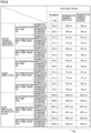
- a segmental mean value D0_m and a segmental standard deviation D0_s are calculated as feature values for inter-vehicle distance D0.
- a segmental mean value D1_m and a segmental standard deviation D1_s are calculated as feature values.
- a segmental mean value D2_m and a segmental standard deviation D2_s are calculated as feature values.
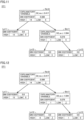
- Fig. 9 is a diagram representing together a traj ectory Tra1 of preceding automobile Ca1 and a traj ectory Trs1 of automobile Cs1 in Fig. 5 when automobile Cs1 is driven by a driver provided with a label indicating that the driver has a high stereognostic ability.
- Fig. 10 is a diagram representing together a trajectory Tra2 of preceding automobile Ca1 and a trajectory Trs2 of automobile Cs1 in Fig. 5 when automobile Cs1 is driven by a driver provided with a label indicating that the driver has a low stereognostic ability. As shown in Fig.
- driver Of 19 drivers (or traveling data as training data) to be classified at root node Rn10, 14 drivers are provided with a label indicating a stereognostic ability (or an objective variable) of a high level ("high”) and 5 drivers are provided with a label indicating a stereognostic ability of a low level (“low”).
- Branch node Bn11 includes feature value D2_ss (a representative segmental standard deviation of segmental standard deviations of interval acceleration D2) as an explanatory variable.
- D2_ss a representative segmental standard deviation of segmental standard deviations of interval acceleration D2
- D2_ss a representative segmental standard deviation of segmental standard deviations of interval acceleration D2
- decision tree DT1 includes feature values D2_ms and D2_ss as explanatory variables. Decision tree DT1 classifies subjects with high stereognostic abilities to leaf nodes Ln11 and Ln13, and classifies subjects with a low stereognostic ability to leaf node Ln12.
- Fig. 12 is a diagram showing a classification result when a driver having a low stereognostic ability is added to be classified according to decision tree DT1 of Fig. 11 .
- 2 drivers with a label "low” are added to be classified at root node Rn10 shown in Fig. 11 .
- the drivers are classified from root node Rn10 through branch node Bn11 to leaf node Ln12, similarly as has been described with reference to Fig. 11 .
- decision tree DT1 has versatility for traveling data other than training data, it can determine a stereognostic ability of a subject with high accuracy.
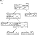
- Branch node Bn22 includes, as an explanatory variable, feature value AS0_ms (a representative segmental standard deviation of segmental mean values of slide amplitude S0 in absolute value AS0).
- AS0_ms a representative segmental standard deviation of segmental mean values of slide amplitude S0 in absolute value AS0.
- AS0_ms a representative segmental standard deviation of segmental mean values of slide amplitude S0 in absolute value AS0.
- Branch node Bn23 includes, as an explanatory variable, feature value AS1_sm (a representative segmental mean value of segmental standard deviations of slide velocity S1 in absolute value AS1).
- AS1_sm a representative segmental mean value of segmental standard deviations of slide velocity S1 in absolute value AS1.
- AS1_sm a representative segmental mean value of segmental standard deviations of slide velocity S1 in absolute value AS1.
- AS1_sm a representative segmental mean value of segmental standard deviations of slide velocity S1 in absolute value AS1
- AS1_sm a representative segmental mean value of segmental standard deviations of slide velocity S1 in absolute value AS1
- decision tree DT2 includes feature values AS0_ss, AS0_ms, AS1_sm, and age as explanatory variables. Decision tree DT2 classifies subjects with high stereognostic abilities to leaf nodes Ln23 and Ln25, and classifies subjects with low stereognostic abilities to leaf nodes Ln21, Ln22 and Ln24.
- Root node Rn30 includes feature value AS0_ss (a representative segmental standard deviation of segmental standard deviations of slide amplitude S0 in absolute value AS0) as an explanatory variable.
- AS0_ss a representative segmental standard deviation of segmental standard deviations of slide amplitude S0 in absolute value AS0
- AS0_ss a representative segmental standard deviation of segmental standard deviations of slide amplitude S0 in absolute value AS0
- the driver is classified to branch node Bn31.
- AS0_ss feature value of 0.093 or less
- AS0_ss of 0.093 or less
- AS0_ss When a driver has feature value AS0_ss larger than 0.093, the driver is classified to leaf node Ln31.
- 16 drivers are classified to branch node Bn31, and 5 drivers are classified to leaf node Ln31. Any driver classified to leaf node Ln31 is labeled "low.”
- 14 drivers are labeled "high” and 2 drivers are labeled "low
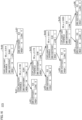
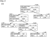
- Fig. 15 is a diagram of another example of decision tree DT of Fig. 2 , showing a decision tree DT4 including, as explanatory variables, feature values derived from slide amplitude S0 in absolute value AS0, slide velocity S1 in absolute value AS1, and slide acceleration S2 in absolute value AS2.
- decision tree DT4 includes a root node Rn40, branch nodes Bn41 and Bn42, and leaf nodes Ln41, Ln42, Ln43 and Ln44.
- 14 drivers are labeled "high” and 7 drivers are labeled "low.”
- Branch node Bn61 includes age as an explanatory variable. When a driver's age is 47 years or younger, the driver is classified to leaf node Ln62. If a driver's age is older than 47 years, the driver is classified to branch node Bn62. Of the 17 drivers to be classified at branch node Bn61, 12 drivers are classified to leaf node Ln62, and 5 drivers are classified to branch node Bn62. Any driver classified to leaf node Ln62 is labeled "high.” Of the 5 drivers classified to branch node Bn62, 2 drivers are labeled "high” and 3 drivers are labeled "low.”
- processor 101 determines whether the driver is changed in S107. When the driver is not changed (NO in S107), processor 101 returns to S102, and writes to storage 103 calculation data including the feature value and/or the like calculated in S105. When the driver is changed (YES in S107), then, in S108, processor 101 writes to storage 103 the calculation data including the feature value and/or the like calculated in S105, and proceeds to S109. In S109, processor 101 uses evaluation model 103c to evaluate subject Sb1's stereognostic ability based on the feature value for the slide amplitude, and proceeds to S114.
- evaluation model 103c trained by machine learning can be used to objectively evaluate a subject's stereognostic ability based on a quantified feature value (see Fig. 8 ).
- the first embodiment has been described a configuration in which information processing device 110 has both a function to evaluate stereognostic ability and a function to train an evaluation model to be a trained evaluation model.
- information processing device 110 has both a function to evaluate stereognostic ability and a function to train an evaluation model to be a trained evaluation model.
- a device has the function to evaluate stereognostic ability and another device has the training function.
- Fig. 19 is a block diagram showing a configuration of a stereognostic ability evaluation system 100A according to an exemplary variation of the first embodiment.
- Stereognostic ability evaluation system 100A is configured such that information processing device 110 shown in Fig. 1 is replaced with an information processing device 110A and a training device 600 is added. Except for this, stereognostic ability evaluation system 100A has a configuration similar to that of stereognostic ability evaluation system 100 of Fig. 1 , and accordingly, will not be described repeatedly for that configuration.
- information processing device 110A, training device 600, terminal device 800, automobile Cs1, and drive recorder 900 are interconnected via network NW.
- Fig. 20 is a diagram showing a hardware configuration of stereognostic ability evaluation system 100A of Fig. 19 .
- Information processing device 110A has a hardware configuration, which is a configuration in which machine learning program 103b and training data 103d are removed from storage 103 in Fig. 2 . Except for this, information processing device 110A has a hardware configuration similar to that of information processing device 110 shown in Fig. 2 , and accordingly, will not be described repeatedly for that hardware configuration.
- Storage 603 stores machine learning program 103b, evaluation model 103c, and training data 103d.
- Processor 601 executes machine learning program 103b to train evaluation model 103c to be a trained evaluation model.
- Processor 601 provides the trained evaluation model 103c to information processing device 110A via communication unit 604.
- a subject's stereognostic ability is evaluated based on a positional change of a moving object operated by the subject in the real world.
- a second embodiment will be described a configuration for evaluating a subject's stereognostic ability based on a positional change of a moving object operated by the subject in a virtual reality (or a virtual space). While, as well as the first embodiment, the second embodiment will also be described with a moving object as an automobile, the moving object is not limited to an automobile. Any moving object may be used insofar as it is positionally changed in response to an operation by the subject, and the moving object may for example be a motorcycle, a bicycle, an airplane, or a ship.
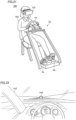
- Fig. 21 is a diagram showing a state in which a subject Sb2 has his/her stereognostic ability measured in a measurement test through a drive simulation in a stereognostic ability evaluation system 200 according to the second embodiment.
- stereognostic ability evaluation system 200 comprises a stereognostic ability evaluation device 210 and a control device Cd.
- Stereognostic ability evaluation device 210 and control device Cd are interconnected wirelessly or by wire.
- Control device Cd includes a handle Hd, an accelerator pedal Ap, and a brake pedal Bp.
- Fig. 22 is a diagram showing an example of a screen displayed for subject Sb2 via stereognostic ability evaluation device 210 in the drive simulation by stereognostic ability evaluation system 200 of Fig. 21 .
- a scenery is displayed as viewed at the driver's seat of an automobile Cs2 (or a moving object) driven by subject Sb2 in a virtual space.
- a preceding automobile Ca2 (or a reference object) traveling in front of automobile Cs2 is displayed.
- Automobile Cs2 moves in the virtual space in response to an input by subject Sb2 to the control device shown in Fig. 21 .
- preceding automobile Ca2 may not be displayed when subject Sb2's stereognostic ability is evaluated by using a feature value for a slide amplitude of automobile Cs2.
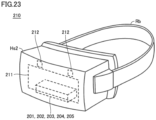
- Stereognostic ability evaluation device 210 is typically a head mounted display (or a goggle) comprising an electronic display that displays a video representing a three-dimensional virtual reality, and is in the form of a virtual reality headset.
- An attachment band Rb such as a rubber band is typically attached to stereognostic ability evaluation device 210.
- a user wears stereognostic ability evaluation device 210 around his/her eyes by placing stereognostic ability evaluation device 210 so as to cover around the eyes and winding attachment band Rb on his/her head.
- Fig. 24 is a diagram showing a hardware configuration of stereognostic ability evaluation device 210 of Fig. 23 .
- stereognostic ability evaluation device 210 includes a processor 201, a RAM 202, a storage 203, a communication unit 204, a memory interface 205, an electronic display 211, and a line-of-sight/pupil sensor 212.
- Processor 201, RAM 202, storage 203, communication unit 204, and memory interface 205 have functions similar to those of the Fig. 2 processor 101, RAM 102, storage 103, communication unit 104, and memory interface 105, respectively, and accordingly, will not be described repeatedly for the functions.
- Storage 203 stores an OS (an operating system) a program (not shown), a stereognostic ability evaluation program 203a, a machine learning program 203b, an evaluation model 203c (a specific model), and training data 203d.
- Electronic display 211 includes, for example, a flat panel display such as a liquid crystal display (LCD) or an organic electro luminescence (EL) display.
- Electronic display 211 displays a video of a moving object moving in a virtual space for a subject wearing stereognostic ability evaluation device 210 around the eyes via an eyepiece disposed on the subject's side.
- LCD liquid crystal display
- EL organic electro luminescence
- Electronic display 211 reads data of image from the data buffer area and displays the video represented by the data.
- Electronic display 211 has an electronic display for the right eye and an electronic display for the left eye independently, and the user sees them through their respective eyepieces.
- the object When the position of an object displayed on electronic display 211 is at infinity, the object is displayed at the same position on electronic displays 211 for the right and left eyes. As a result, no parallax is caused between the right and left eyes, and the right and left eyes are diverged, whereby a sense of presence at infinity can be given to the subject. As the position of the object approaches the user, the object is displayed inward on electronic display 211 for the right eye and electronic display 211 for the left eye. As a result, a parallax is caused between the right and left eyes, and the right and left eyes are converged, whereby a sense of presence close to the subject can be given to the subject.
- Line-of-sight/pupil sensor 212 is disposed on an upper side of electronic display 211 toward the subject and senses the direction of the line of sight of each of the right and left eyes as well as the pupillary size of each eye.
- Line-of-sight/pupil sensor 212 acquires images of the right and left eyes by an image acquisition means such as a camera, determines a pupillary position and size in the images to determine a direction of a line of sight and a pupillary size, and outputs them as line-of-sight information to processor 201.
- the camera can be a visible light camera or an infrared camera. In order to determine that the subject visually recognizes the moving object, first of all, the direction of a line of sight is important data.
- a pupillary diameter can be additionally used in order to determine that the subject is continuously visually recognizing a moving object approaching the subject.
- the subject's pupils become gradually smaller in diameter due to near pupillary reflex, and by detecting it, it can be confirmed whether the subject visually recognizes the moving object.
- Stereognostic ability is predicated on a normal function of an eye (e.g., pupillary accommodation or eye movement) for acquisition of visual information. Therefore, a stereognostic ability is defined for example as an ability of a subject who observes a moving object to cerebrally, accurately understand a positional relationship of the moving object from visual information of the moving object and perform an operation corresponding to the moving object appropriately and accurately based on the understood positional relationship.
- a stereognostic ability also includes an ability to ocularly, accurately track a moving object, correctly recognize its position, and accurately respond thereto, in particular.
- measuring pupillary accommodation and convergence response is considered particularly useful.
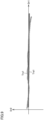
- Fig. 25 is a diagram representing a concept of a visual target used for measuring a function of eyes.
- the visual target (or preceding automobile Ca2) moves between a direction in which it moves away from the subject's eyes and a direction in which it approaches the subject's eyes such that it is visually recognized by the subject in front of his/her eyes. It is desirable to check the state of the eyes of the subject whenever the visual target is moved back and forth.
- Fig. 26 is a diagram representing a relationship between a visual target's distance (a distance between an eye of a subject and the visual target) and pupillary diameter through near pupillary reflex.
- Fig. 26(A) shows that pupillary diameter decreases when the visual target's distance is short.
- Fig. 26(B) shows that pupillary diameter increases when the visual target's distance is long.
- Fig. 26(C) is a graph when the horizontal axis represents the visual target's distance and the vertical axis represents pupillary diameter.
- a solid line represents a graph of the left eye
- a dot-and-dash line represents a graph of the right eye.
- Fig. 27 is a diagram representing a relationship between a visual target's distance and pupillary position (or vergence).
- Fig. 27(A) shows that the right and left eyes turned inward or converged when the visual target's distance is short.
- Fig. 27(B) shows that the right and left eyes turned outward or diverged when the visual target's distance is long.
- Fig. 27(C) is a graph when the horizontal axis represents the visual target's distance and the vertical axis represents pupillary position.
- a solid line represents a graph of the left eye
- a dot-and-dash line represents a graph of the right eye.
- Stereognostic ability evaluation system 200 can dispense with a large-sized device to move a visual target to be near/far, and thus be miniaturized.
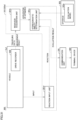
- Fig. 28 is a functional block diagram showing a configuration of a function of processor 201 of Fig. 24 to evaluate stereognostic ability.
- processor 201 executes a stereognostic ability evaluation program 203a stored in storage 203 to configure a module forming functional blocks of a moving-object display unit 201a, a position acquisition unit 201b, a visual recognition determination unit 201c, a reaction input unit 201d, and a stereognostic ability determination unit 201e. Therefore, in place of processor 201 and stereognostic ability evaluation program 203a of Fig. 24 , Fig. 28 shows functional blocks implemented thereby. These functional blocks will now be described below.
- Moving-object display unit 201a continuously generates images of a scenery in front as viewed by subject Sb2 at the driver's seat of automobile Cs2 by three-dimensional rendering as automobile Cs2 proceeds, and transfers the images as video data to a data buffer area of electronic display 211.
- the video data is data for each of the right eye and the left eye for electronic display 211.
- the video data causes a parallax between the video data for the right eye and the video data for the left eye at a position in the scenery seen by subject Sb2 from automobile Cs2. Therefore, the subject who views the video data on electronic display 211 can view a ball with a realistic perspective.
- Moving-object display unit 201a transmits traveling data of automobile Cs2 based on the video data to position acquisition unit 201b.
- Position acquisition unit 201b acquires traveling data of subject Sb2 from moving-object display unit 201a. Position acquisition unit 201b acquires information about a position of automobile Cs2 from the traveling data. Position acquisition unit 201b outputs the information about the position of automobile Cs2 to visual recognition determination unit 201c and stereognostic ability determination unit 201e.
- Visual recognition determination unit 201c determines whether the subject's line of sight is in a direction correctly corresponding to the position of automobile Cs2 to determine whether subject Sb2 visually, spatially recognizes automobile Cs2.
- Visual recognition determination unit 201c receives the data of the directions of the lines of sight of the right and left eyes of subject Sb2 as sensed by line-of-sight/pupil sensor 212, and determines whether the directions of the lines of sight of the right and left eyes correspond to the position of automobile Cs2 as transmitted from moving-object display unit 201a to determine whether subject Sb2 spatially recognizes automobile Cs2.
- Visual recognition determination unit 201c may further receive data of the pupillary diameters of the right and left eyes of subject Sb2 as sensed by line-of-sight/pupil sensor 212. Visual recognition determination unit 201c may operate to determine that the subject spatially recognizes an object when it is further determined that the subject's both eyes have a gradually decreasing pupillary diameter while preceding automobile Ca2 positionally approaches a predetermined viewpoint and thus has a smaller distance to the subject (that is, when near pupillary reflex occurs in response to a reduced distance). Visual recognition determination unit 201c outputs the determination result as visual recognition information to stereognostic ability determination unit 201e.
- Reaction input unit 201d receives an input of an active reaction made by subject Sb2 to correspond to a three-dimensional position of automobile Cs2 as recognized by subject Sb2 in a virtual space. Based on the information input by subject Sb2 to control device Cd, reaction input unit 201d determines the reaction of subject Sb2 driving automobile Cs2. Reaction input unit 201d outputs information about the reaction to stereognostic ability determination unit 201e.
- stereognostic ability determination unit 201e Based on the information about the position of automobile Cs2, stereognostic ability determination unit 201e derives a feature value derived from at least one of an interval velocity of automobile Cs2, an interval acceleration thereof, a slide amplitude in absolute value thereof, a slide velocity in absolute value thereof, a slide acceleration in absolute value thereof, the slide amplitude, the slide velocity, and the slide acceleration.
- Stereognostic ability determination unit 201e uses evaluation model 203c to determine the stereognostic ability of subject Sb2 from the feature value and the visual recognition information received from visual recognition determination unit 201c.
- the visual recognition information may not be used to determine the stereognostic ability of subject Sb2.
- the information received from reaction input unit 201d about the reaction may be used to determine the stereognostic ability of subject Sb2.
- Stereognostic ability determination unit 201e transmits an evaluation result of the stereognostic ability to a terminal device 820 of subject Sb2 via communication unit 204.
- stereognostic ability evaluation device 210 when machine learning program 203b is executed by processor 201, stereognostic ability evaluation device 210 functions as a training device to train evaluation model 203c to be a trained evaluation model. As well as in the exemplary variation of the first embodiment, a training device separate from stereognostic ability evaluation device 210 may subject evaluation model 203c to machine learning.
- Fig. 29 is a flowchart of a process in a stereognostic ability evaluation method performed by processor 201 executing stereognostic ability evaluation program 203a of Fig. 24 .
- the flowchart of the process shown in Fig. 29 corresponds to that shown in Fig. 18 with S204 added between S103 and S105, and S109 and S113 replaced with S209 and S213, respectively.
- processor 201 acquires line-of-sight information from line-of-sight/pupil sensor 212 in S204, and proceeds to S105.
- processor 201 uses evaluation model 203c to evaluate subject Sb2's stereognostic ability in each of S209 and S213 based on a feature value for a slide amplitude and visual recognition information, and proceeds to S 114.
- processor 201 performs S 114 and ends the process.
- a feature value is calculated from a position of a moving object as measured by a position measurement unit of a drive recorder.
- a third embodiment will be described a configuration in which a feature value is directly measured by an acceleration sensor of a drive recorder.
- Fig. 30 is a diagram showing a hardware configuration of a stereognostic ability evaluation system 300 according to the third embodiment.
- An information processing device 310 shown in Fig. 30 has a configuration in which the Fig. 2 stereognostic ability evaluation program 103a, machine learning program 103b, evaluation model 103c, and training data 103d are replaced with a stereognostic ability evaluation program 303a, a machine learning program 303b, an evaluation model 303c, and training data 303d, respectively.
- a drive recorder 930 shown in Fig. 30 has a configuration in which position measurement unit 907 shown in Fig. 2 is replaced with an acceleration sensor 937.
- Acceleration sensor 937 measures, for example, an acceleration of automobile Cs1 in a direction (a lateral direction) orthogonal to a reference line extending in a direction in which automobile Cs1 travels. Acceleration sensor 937 may measure an acceleration of automobile Cs1 in a direction along the reference line. Except for this, stereognostic ability evaluation system 300 has a configuration similar to that of stereognostic ability evaluation system 100, and accordingly, will not be described repeatedly for that configuration.
- Reaction input unit 301d receives an input of an active reaction made by the subject to correspond to a three-dimensional position of automobile Cs1 as recognized by the subject. Reaction input unit 301d determines the reaction of the subject driving automobile Cs1, based on information input by the subject to the handle, accelerator pedal, brake pedal, etc. of automobile Cs1. Reaction input unit 301d outputs information about the reaction to stereognostic ability determination unit 301e.
- Stereognostic ability determination unit 301e uses evaluation model 303c to determine the stereognostic ability of the subject from the acceleration of automobile Cs1. The information received from reaction input unit 301d about the reaction may be used to determine the stereognostic ability of the subject. As well as stereognostic ability determination unit 101e of the first embodiment, stereognostic ability determination unit 301e transmits an evaluation result of the stereognostic ability to terminal device 800 of the subject via communication unit 104.
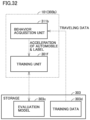
- Fig. 32 is a functional block diagram of processor 101 of Fig. 30 showing a configuration of a machine learning function.
- processor 101 executes machine learning program 303b to configure a module forming functional blocks referred to as a behavior acquisition unit 311b and a training unit 301f. Accordingly, in place of processor 101 and machine learning program 303b shown in Fig. 30 , Fig. 32 shows functional blocks implemented thereby. The functional blocks will now be described below.
- Training unit 301f uses the acceleration and the label received from behavior acquisition unit 311b to subject evaluation model 303c to machine learning to train evaluation model 303c.
- Table 1 below indicates an example of correlation coefficients between each of feature values S0_s, S1_s and S2_s derived from a slide acceleration obtained by acceleration sensor 937 and each of feature values S0_s and AS1_s derived from a slide amplitude in a virtual space as obtained by the stereognostic ability evaluation system according to the second embodiment for a plurality of subjects. Note that each feature value indicated in Table 1 corresponds to a feature value indicated in Fig. 8 that is the same character string as the feature value. [Table 1] acceleration sensor S0_s S1_s S2_s virtual space S0_s 0.73 0.35 0.14 AS1_s 0.87 0.56 0.38
- feature value S2_s is a segmental standard deviation of the slide acceleration acquired by acceleration sensor 937.
- Feature value S1_s is a segmental standard deviation of slide velocity, and is derived by integrating feature value S2_s over time once.
- Feature value S0_s is a segmental standard deviation of slide amplitude, and is derived by integrating feature value S1_s over time once (or integrating feature value S2_s over time twice).
- the slide acceleration acquired by acceleration sensor 937 can be obtained, for example, from a drive recorder of an automobile running a course of a driving school including an S-curve, a dogleg, a straight line, and the like.
- the presently disclosed stereognostic ability evaluation system evaluates a subject's stereognostic ability based on a behavioral change of a moving object moving as operated by the subject.
- the stereognostic ability evaluation system comprises a behavior acquisition unit and a stereognostic ability determination unit.
- the stereognostic ability determination unit determines the stereognostic ability of the subject from at least one of a first feature value and a second feature value, the first feature value being relevant to a first distance between a reference object preceding the moving object in the direction in which the moving object travels and the moving object, the second feature value being relevant to a second distance between a reference line extending in the direction in which the moving object travels and the moving object. Further, the behavior acquisition unit acquires information about an acceleration of the moving object.
- the first feature value and/or the second feature value are feature values derived from the information about the acceleration of the moving object.
- the first feature value for the first distance may be derived from any one of a value of the acceleration in the direction of the first distance, a value obtained by integrating the acceleration in the direction of the first distance over time once, and a value obtained by integrating the acceleration in the direction of the first distance over time twice.
- the second feature value for the second distance may be derived from any one of a value of the acceleration in the direction of the second distance, a value obtained by integrating the acceleration in the direction of the second distance over time once, and a value obtained by integrating the acceleration in the direction of the second distance over time twice.
- a gyro sensor (or an angular velocity sensor) may be used in place of the acceleration sensor, or both the acceleration sensor and the gyro sensor may be used together.
- a feature value for determining a stereognostic ability may be derived from any one of a value of an angular velocity, a value obtained by integrating the angular velocity over time once, and a value obtained by integrating the angular velocity over time twice.
- stereognostic ability evaluation system stereognostic ability evaluation device, stereognostic ability evaluation program, and stereognostic ability evaluation method according to the third embodiment and the exemplary variation thereof can implement objective evaluation of stereognostic ability.
- stereognostic ability evaluation system can implement objective evaluation of stereognostic ability.
- stereognostic ability described in implementations of the present disclosure can be utilized in a variety of scenes.
- the evaluation can be used as an indicator for development of higher cerebral functions in a human growth process.
- a stereognostic ability has been evaluated based on solving a problem in a quiz format or on empirical rules in sports or the like.
- quantitatively evaluating a stereognostic ability using the stereognostic ability evaluation system, stereognostic ability evaluation device, stereognostic ability evaluation program, and stereognostic ability evaluation method described herein allows a more precise evaluation of stereognostic ability.
- 100, 100A, 200, 300, 300A stereognostic ability evaluation system 101, 201, 601, 901 processor, 101b, 111b, 201b position acquisition unit, 101d, 201d, 301d reaction input unit, 101e, 201e, 301e stereognostic ability determination unit, 101f, 301f training unit, 102, 202, 602, 903 RAM, 103, 203, 603, 905 storage, 103a, 203a, 303a stereognostic ability evaluation program, 103b, 203b, 303b machine learning program, 103c, 203c, 303c evaluation model, 103d, 203d, 303d training data, 104, 204, 604, 904 communication unit, 105, 205, 605, 906 memory interface, 110, 110A, 310 information processing device, 201a moving-object display unit, 201c visual recognition determination unit, 210 stereognostic ability evaluation device, 211 electronic display, 212 pupil sensor, 301b, 311b behavior acquisition unit
Landscapes
- Engineering & Computer Science (AREA)
- Theoretical Computer Science (AREA)
- Health & Medical Sciences (AREA)
- Physics & Mathematics (AREA)
- General Physics & Mathematics (AREA)
- General Engineering & Computer Science (AREA)
- Public Health (AREA)
- Medical Informatics (AREA)
- Life Sciences & Earth Sciences (AREA)
- Biomedical Technology (AREA)
- Human Computer Interaction (AREA)
- General Health & Medical Sciences (AREA)
- Heart & Thoracic Surgery (AREA)
- Aviation & Aerospace Engineering (AREA)
- Educational Administration (AREA)
- Biophysics (AREA)
- Business, Economics & Management (AREA)
- Molecular Biology (AREA)
- Surgery (AREA)
- Animal Behavior & Ethology (AREA)
- Educational Technology (AREA)
- Ophthalmology & Optometry (AREA)
- Veterinary Medicine (AREA)
- Primary Health Care (AREA)
- Data Mining & Analysis (AREA)
- Databases & Information Systems (AREA)
- Pathology (AREA)
- Epidemiology (AREA)
- Computer Vision & Pattern Recognition (AREA)
- Image Analysis (AREA)
Applications Claiming Priority (3)
| Application Number | Priority Date | Filing Date | Title |
|---|---|---|---|
| JP2021141500 | 2021-08-31 | ||
| JP2022030855 | 2022-03-01 | ||
| PCT/JP2022/032035 WO2023032806A1 (fr) | 2021-08-31 | 2022-08-25 | Système, dispositif, programme et procédé d'évaluation de capacités stéréognostiques |
Publications (2)
| Publication Number | Publication Date |
|---|---|
| EP4398261A1 true EP4398261A1 (fr) | 2024-07-10 |
| EP4398261A4 EP4398261A4 (fr) | 2025-08-13 |
Family
ID=85412661
Family Applications (1)
| Application Number | Title | Priority Date | Filing Date |
|---|---|---|---|
| EP22864390.4A Pending EP4398261A4 (fr) | 2021-08-31 | 2022-08-25 | Système, dispositif, programme et procédé d'évaluation de capacités stéréognostiques |
Country Status (5)
| Country | Link |
|---|---|
| US (1) | US20240377192A1 (fr) |
| EP (1) | EP4398261A4 (fr) |
| JP (1) | JP7602706B2 (fr) |
| CA (1) | CA3230535A1 (fr) |
| WO (1) | WO2023032806A1 (fr) |
Families Citing this family (1)
| Publication number | Priority date | Publication date | Assignee | Title |
|---|---|---|---|---|
| WO2025121417A1 (fr) * | 2023-12-07 | 2025-06-12 | 株式会社do.Sukasu | Système d'évaluation de capacité cognitive tridimensionnelle, dispositif d'évaluation de capacité cognitive tridimensionnelle, programme d'évaluation de capacité cognitive tridimensionnelle et procédé d'évaluation de capacité cognitive tridimensionnelle |
Family Cites Families (6)
| Publication number | Priority date | Publication date | Assignee | Title |
|---|---|---|---|---|
| JPH1165418A (ja) * | 1997-08-26 | 1999-03-05 | Tasuku Net Kk | 運転シミュレータ装置および運転シミュレート方法 |
| ES2831648T3 (es) | 2010-11-24 | 2021-06-09 | Digital Artefacts Llc | Sistemas y métodos para evaluar la función cognitiva |
| EP2793682A1 (fr) | 2011-12-20 | 2014-10-29 | ICheck Health Connection Inc. | Jeu vidéo pour contrôler une perte de champ visuel due à un glaucome |
| JP2018124789A (ja) | 2017-01-31 | 2018-08-09 | 富士通株式会社 | 運転評価装置、運転評価方法及び運転評価システム |
| DE112019004143T5 (de) | 2018-08-17 | 2021-06-10 | Sony Corporation | Informationsverarbeitungsvorrichtung, informationsverarbeitungssystem, informationsverarbeitungsverfahren und programm |
| CN112434573A (zh) | 2020-11-10 | 2021-03-02 | 易显智能科技有限责任公司 | 一种评价驾驶员空间感知能力的方法及装置 |
-
2022
- 2022-08-25 WO PCT/JP2022/032035 patent/WO2023032806A1/fr not_active Ceased
- 2022-08-25 CA CA3230535A patent/CA3230535A1/fr active Pending
- 2022-08-25 JP JP2023513771A patent/JP7602706B2/ja active Active
- 2022-08-25 EP EP22864390.4A patent/EP4398261A4/fr active Pending
- 2022-08-25 US US18/688,259 patent/US20240377192A1/en active Pending
Also Published As
| Publication number | Publication date |
|---|---|
| WO2023032806A1 (fr) | 2023-03-09 |
| US20240377192A1 (en) | 2024-11-14 |
| JPWO2023032806A1 (fr) | 2023-03-09 |
| EP4398261A4 (fr) | 2025-08-13 |
| JP7602706B2 (ja) | 2024-12-19 |
| CA3230535A1 (fr) | 2023-03-09 |
Similar Documents
| Publication | Publication Date | Title |
|---|---|---|
| US10568502B2 (en) | Visual disability detection system using virtual reality | |
| EP3042152B1 (fr) | Procédé de navigation basé sur un dispositif transparent monté sur la tête | |
| CN110022835B (zh) | 康复支援系统、康复支援方法及存储介质 | |
| JP6774975B2 (ja) | 眼球回転検出装置、電子機器及びシステム | |
| US20130171596A1 (en) | Augmented reality neurological evaluation method | |
| US11826160B2 (en) | Nerve disorder diagnosis apparatus and method using virtual reality | |
| WO2019208450A1 (fr) | Dispositif d'aide à la conduite, procédé d'aide à la conduite et programme | |
| US20180206773A1 (en) | Dynamic assessment and rehabilitation system for vertigo patients and the application method thereof | |
| CN107092314A (zh) | 一种提供驾驶适宜性检测的头戴式显示设备及检测方法 | |
| JP2019076290A (ja) | リハビリテーション支援システム、リハビリテーション支援方法およびリハビリテーション支援プログラム | |
| EP4398261A1 (fr) | Système, dispositif, programme et procédé d'évaluation de capacités stéréognostiques | |
| AU2017402745B2 (en) | Visual performance assessment | |
| JP7099377B2 (ja) | 情報処理装置及び情報処理方法 | |
| Sessner et al. | Multimodal feedback to support the navigation of visually impaired people | |
| US20240362951A1 (en) | Augmented reality device for providing guide for user's activity, and operating method thereof | |
| Kono et al. | Suppression of vestibulo-ocular reflex with increased mental workload while driving | |
| JP2019076703A (ja) | リハビリテーション支援システム、リハビリテーション支援方法およびリハビリテーション支援プログラム | |
| CN117882147A (zh) | 立体认知能力评价系统、立体认知能力评价装置、立体认知能力评价程序以及立体认知能力评价方法 | |
| JP7218978B2 (ja) | リハビリテーション支援システム、リハビリテーション支援方法およびリハビリテーション支援プログラム | |
| US11270451B2 (en) | Motion parallax in object recognition | |
| HK40105013A (zh) | 立体认知能力评价系统、立体认知能力评价装置、立体认知能力评价程序以及立体认知能力评价方法 | |
| WO2025121417A1 (fr) | Système d'évaluation de capacité cognitive tridimensionnelle, dispositif d'évaluation de capacité cognitive tridimensionnelle, programme d'évaluation de capacité cognitive tridimensionnelle et procédé d'évaluation de capacité cognitive tridimensionnelle | |
| CN113325991A (zh) | 显示界面调整方法、装置、设备、介质及程序产品 | |
| JP7149658B2 (ja) | リハビリテーション支援システム、リハビリテーション支援方法およびリハビリテーション支援プログラム | |
| JP7164917B1 (ja) | リハビリテーション支援システム及びリハビリテーション支援方法 |
Legal Events
| Date | Code | Title | Description |
|---|---|---|---|
| STAA | Information on the status of an ep patent application or granted ep patent |
Free format text: STATUS: THE INTERNATIONAL PUBLICATION HAS BEEN MADE |
|
| PUAI | Public reference made under article 153(3) epc to a published international application that has entered the european phase |
Free format text: ORIGINAL CODE: 0009012 |
|
| STAA | Information on the status of an ep patent application or granted ep patent |
Free format text: STATUS: REQUEST FOR EXAMINATION WAS MADE |
|
| 17P | Request for examination filed |
Effective date: 20240228 |
|
| AK | Designated contracting states |
Kind code of ref document: A1 Designated state(s): AL AT BE BG CH CY CZ DE DK EE ES FI FR GB GR HR HU IE IS IT LI LT LU LV MC MK MT NL NO PL PT RO RS SE SI SK SM TR |
|
| DAV | Request for validation of the european patent (deleted) | ||
| DAX | Request for extension of the european patent (deleted) | ||
| RAP1 | Party data changed (applicant data changed or rights of an application transferred) |
Owner name: FRONTACT CO., LTD. |
|
| A4 | Supplementary search report drawn up and despatched |
Effective date: 20250710 |
|
| RIC1 | Information provided on ipc code assigned before grant |
Ipc: G16H 50/30 20180101AFI20250704BHEP Ipc: G06F 3/01 20060101ALI20250704BHEP Ipc: G06F 3/04815 20220101ALI20250704BHEP |