EP4398334A1 - Positivelektrodenmaterial für eine elektrische vorrichtung und positivelektrode für eine elektrische vorrichtung und elektrische vorrichtung damit - Google Patents
Positivelektrodenmaterial für eine elektrische vorrichtung und positivelektrode für eine elektrische vorrichtung und elektrische vorrichtung damit Download PDFInfo
- Publication number
- EP4398334A1 EP4398334A1 EP21955283.3A EP21955283A EP4398334A1 EP 4398334 A1 EP4398334 A1 EP 4398334A1 EP 21955283 A EP21955283 A EP 21955283A EP 4398334 A1 EP4398334 A1 EP 4398334A1
- Authority
- EP
- European Patent Office
- Prior art keywords
- positive electrode
- active material
- electrode active
- electric device
- solid electrolyte
- Prior art date
- Legal status (The legal status is an assumption and is not a legal conclusion. Google has not performed a legal analysis and makes no representation as to the accuracy of the status listed.)
- Withdrawn
Links
Images


Classifications
-
- H—ELECTRICITY
- H01—ELECTRIC ELEMENTS
- H01M—PROCESSES OR MEANS, e.g. BATTERIES, FOR THE DIRECT CONVERSION OF CHEMICAL ENERGY INTO ELECTRICAL ENERGY
- H01M4/00—Electrodes
- H01M4/02—Electrodes composed of, or comprising, active material
- H01M4/13—Electrodes for accumulators with non-aqueous electrolyte, e.g. for lithium-accumulators; Processes of manufacture thereof
- H01M4/136—Electrodes based on inorganic compounds other than oxides or hydroxides, e.g. sulfides, selenides, tellurides, halogenides or LiCoFy
-
- H—ELECTRICITY
- H01—ELECTRIC ELEMENTS
- H01M—PROCESSES OR MEANS, e.g. BATTERIES, FOR THE DIRECT CONVERSION OF CHEMICAL ENERGY INTO ELECTRICAL ENERGY
- H01M10/00—Secondary cells; Manufacture thereof
- H01M10/05—Accumulators with non-aqueous electrolyte
- H01M10/052—Li-accumulators
- H01M10/0525—Rocking-chair batteries, i.e. batteries with lithium insertion or intercalation in both electrodes; Lithium-ion batteries
-
- H—ELECTRICITY
- H01—ELECTRIC ELEMENTS
- H01M—PROCESSES OR MEANS, e.g. BATTERIES, FOR THE DIRECT CONVERSION OF CHEMICAL ENERGY INTO ELECTRICAL ENERGY
- H01M10/00—Secondary cells; Manufacture thereof
- H01M10/05—Accumulators with non-aqueous electrolyte
- H01M10/056—Accumulators with non-aqueous electrolyte characterised by the materials used as electrolytes, e.g. mixed inorganic/organic electrolytes
- H01M10/0561—Accumulators with non-aqueous electrolyte characterised by the materials used as electrolytes, e.g. mixed inorganic/organic electrolytes the electrolyte being constituted of inorganic materials only
- H01M10/0562—Solid materials
-
- H—ELECTRICITY
- H01—ELECTRIC ELEMENTS
- H01M—PROCESSES OR MEANS, e.g. BATTERIES, FOR THE DIRECT CONVERSION OF CHEMICAL ENERGY INTO ELECTRICAL ENERGY
- H01M4/00—Electrodes
- H01M4/02—Electrodes composed of, or comprising, active material
- H01M4/13—Electrodes for accumulators with non-aqueous electrolyte, e.g. for lithium-accumulators; Processes of manufacture thereof
-
- H—ELECTRICITY
- H01—ELECTRIC ELEMENTS
- H01M—PROCESSES OR MEANS, e.g. BATTERIES, FOR THE DIRECT CONVERSION OF CHEMICAL ENERGY INTO ELECTRICAL ENERGY
- H01M4/00—Electrodes
- H01M4/02—Electrodes composed of, or comprising, active material
- H01M4/36—Selection of substances as active materials, active masses, active liquids
- H01M4/38—Selection of substances as active materials, active masses, active liquids of elements or alloys
- H01M4/381—Alkaline or alkaline earth metals elements
- H01M4/382—Lithium
-
- H—ELECTRICITY
- H01—ELECTRIC ELEMENTS
- H01M—PROCESSES OR MEANS, e.g. BATTERIES, FOR THE DIRECT CONVERSION OF CHEMICAL ENERGY INTO ELECTRICAL ENERGY
- H01M4/00—Electrodes
- H01M4/02—Electrodes composed of, or comprising, active material
- H01M4/36—Selection of substances as active materials, active masses, active liquids
- H01M4/58—Selection of substances as active materials, active masses, active liquids of inorganic compounds other than oxides or hydroxides, e.g. sulfides, selenides, tellurides, halogenides or LiCoFy; of polyanionic structures, e.g. phosphates, silicates or borates
- H01M4/581—Chalcogenides or intercalation compounds thereof
- H01M4/5815—Sulfides
-
- H—ELECTRICITY
- H01—ELECTRIC ELEMENTS
- H01M—PROCESSES OR MEANS, e.g. BATTERIES, FOR THE DIRECT CONVERSION OF CHEMICAL ENERGY INTO ELECTRICAL ENERGY
- H01M4/00—Electrodes
- H01M4/02—Electrodes composed of, or comprising, active material
- H01M4/62—Selection of inactive substances as ingredients for active masses, e.g. binders, fillers
- H01M4/624—Electric conductive fillers
- H01M4/625—Carbon or graphite
-
- H—ELECTRICITY
- H01—ELECTRIC ELEMENTS
- H01M—PROCESSES OR MEANS, e.g. BATTERIES, FOR THE DIRECT CONVERSION OF CHEMICAL ENERGY INTO ELECTRICAL ENERGY
- H01M4/00—Electrodes
- H01M4/02—Electrodes composed of, or comprising, active material
- H01M4/62—Selection of inactive substances as ingredients for active masses, e.g. binders, fillers
- H01M4/624—Electric conductive fillers
- H01M4/626—Metals
-
- H—ELECTRICITY
- H01—ELECTRIC ELEMENTS
- H01M—PROCESSES OR MEANS, e.g. BATTERIES, FOR THE DIRECT CONVERSION OF CHEMICAL ENERGY INTO ELECTRICAL ENERGY
- H01M4/00—Electrodes
- H01M4/02—Electrodes composed of, or comprising, active material
- H01M2004/026—Electrodes composed of, or comprising, active material characterised by the polarity
- H01M2004/028—Positive electrodes
-
- H—ELECTRICITY
- H01—ELECTRIC ELEMENTS
- H01M—PROCESSES OR MEANS, e.g. BATTERIES, FOR THE DIRECT CONVERSION OF CHEMICAL ENERGY INTO ELECTRICAL ENERGY
- H01M2220/00—Batteries for particular applications
- H01M2220/20—Batteries in motive systems, e.g. vehicle, ship, plane
-
- H—ELECTRICITY
- H01—ELECTRIC ELEMENTS
- H01M—PROCESSES OR MEANS, e.g. BATTERIES, FOR THE DIRECT CONVERSION OF CHEMICAL ENERGY INTO ELECTRICAL ENERGY
- H01M2300/00—Electrolytes
- H01M2300/0017—Non-aqueous electrolytes
- H01M2300/0065—Solid electrolytes
- H01M2300/0068—Solid electrolytes inorganic
- H01M2300/008—Halides
-
- Y—GENERAL TAGGING OF NEW TECHNOLOGICAL DEVELOPMENTS; GENERAL TAGGING OF CROSS-SECTIONAL TECHNOLOGIES SPANNING OVER SEVERAL SECTIONS OF THE IPC; TECHNICAL SUBJECTS COVERED BY FORMER USPC CROSS-REFERENCE ART COLLECTIONS [XRACs] AND DIGESTS
- Y02—TECHNOLOGIES OR APPLICATIONS FOR MITIGATION OR ADAPTATION AGAINST CLIMATE CHANGE
- Y02E—REDUCTION OF GREENHOUSE GAS [GHG] EMISSIONS, RELATED TO ENERGY GENERATION, TRANSMISSION OR DISTRIBUTION
- Y02E60/00—Enabling technologies; Technologies with a potential or indirect contribution to GHG emissions mitigation
- Y02E60/10—Energy storage using batteries
Definitions
- a secondary battery for motor driving is required to have extremely high output characteristics and high energy as compared with a lithium secondary battery for consumer use used in a mobile phone, a notebook computer, and the like. Therefore, a lithium secondary battery having the highest theoretical energy among all practical batteries has attracted attention, and is currently being rapidly developed.
- lithium secondary batteries that are currently widespread use a combustible organic electrolyte solution as an electrolyte.
- safety measures against liquid leakage, short circuit, overcharge, and the like are more strictly required than other batteries.
- the solid electrolyte is a material mainly made of an ion conductor that enables ion conduction in a solid. For this reason, in an all solid lithium secondary battery, in principle, various problems caused by combustible organic electrolyte solution do not occur unlike the conventional liquid-based lithium secondary battery.
- use of a high-potential and large-capacity positive electrode material and a large-capacity negative electrode material can achieve significant improvement in output density and energy density of a battery.
- elemental sulfur (S 8 ) has an extremely large theoretical capacity of about 1670 mAh/g, and has the advantage of being abundant in resources at low cost.
- JP 2014-17241 A discloses a method for producing a thin-film sulfur-coated conductive carbon including immersing a conductive carbon having a predetermined specific surface area in a sulfur solution and then separating the conductive carbon from the sulfur solution.
- the obtained thin-film sulfur-coated conductive carbon tends to diffuse electrons and lithium ions inside sulfur, and thus can be used as a positive electrode mixture to provide an all-solid-state lithium sulfur battery having excellent discharge capacity and rate characteristics.
- the laminate type battery 10a of the present embodiment has a structure in which the flat and substantially rectangular power-generating element 21 in which a charge and discharge reaction actually proceeds is sealed inside the laminate film 29 as the battery outer casing material.
- the power-generating element 21 has a configuration in which a positive electrode, a solid electrolyte layer 17, and a negative electrode are laminated.
- the positive electrode has a structure in which a positive electrode active material layer 15 containing a positive electrode active material is disposed on both surfaces of a positive electrode current collector 11".
- the negative electrode has a structure in which a negative electrode active material layer 13 containing a negative electrode active material is disposed on both surfaces of a negative electrode current collector 11'.
- the positive electrode, solid electrolyte layer, and negative electrode that are adjacent constitute one single battery layer 19.
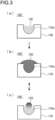
- the inside of the pores 110a is filled with an electronic conductor 130 (e.g., carbon fiber) together with the positive electrode active material 120 (state of (a) in Fig. 4 ).
- the positive electrode active material 120 expands by storing lithium ions.
- a part of the positive electrode active material 120 and a part of the electronic conductor 130 that are filled in the pores 110a are both pushed out of the pores 110a (state of (b) in Fig. 4 ).
- the positive electrode active material 120 contracts by releasing lithium ions.
- the positive electrode material according to the present embodiment essentially contains a positive electrode active material containing sulfur as the positive electrode active material.
- the type of the positive electrode active material containing sulfur is not particularly limited, and examples thereof include particles or a thin film of an organic sulfur compound or an inorganic sulfur compound in addition to sulfur simple substance (S) and lithium sulfide (Li 2 S). Any material may be used as long as the material can release lithium ions during charging and occlude lithium ions during discharging by utilizing the oxidation-reduction reaction of sulfur.
- the inorganic sulfur compound is preferred because it is excellent in stability, and specific examples thereof include sulfur simple substance (S), TiS 2 , TiS 3 , TiS 4 , NiS, NiS 2 , CuS, FeS 2 , Li 2 S, MoS 2 , MoS 3 , MnS, MnS 2 , CoS, CoS 2 , and the like.
- examples of the alloy include stainless steel (SUS), Inconel (registered trademark), Hastelloy (registered trademark), other Fe-Cr-based alloys, and Ni-Cr alloys.
- the metal oxide include titanium oxide (TiO 2 ), zinc oxide (ZnO), indium oxide (In 2 O 3 ), tin oxide (SnO 2 ), and indium tin oxide (Indium Tin Oxide; ITO), vanadium oxide (V 2 O 5 ), triiron tetraoxide (Fe 3 O 4 ), zirconium oxide (ZrO 2 ), tungsten oxide (IV) (WO 2 ), and the like.
- the thickness of the positive electrode active material layer varies depending on the configuration of the intended lithium secondary battery, but is preferably, for example, within a range of 0.1 to 1000 um.
- the laminate type battery according to the present embodiment has a configuration in which a plurality of single battery layers is connected in parallel, and thus has a high capacity and excellent cycle durability. Therefore, the laminate type battery according to the present embodiment is suitably used as a power source for driving EV and HEV.
- the type of electric device to which the positive electrode material according to the present embodiment is applied is a bipolar type (bipolar type) battery including a bipolar electrode having a positive electrode active material layer electrically coupled to one surface of a current collector and a negative electrode active material layer electrically coupled to an opposite surface of the current collector.
- bipolar type bipolar type
- An assembled battery is one configured by connecting a plurality of batteries.
- the assembled battery is one configured by serializing, parallelizing, or both serializing and parallelizing at least two or more batteries. It is possible to freely adjust the capacity and the voltage by serializing and parallelizing the batteries.
- a plurality of batteries may be connected in series or in parallel to form an attachable and detachable compact assembled battery. Further, a plurality of such attachable and detachable compact assembled batteries may be connected in series or in parallel to form an assembled battery (such as a battery module or a battery pack) having a large capacity and a large output suitable for a power source for driving a vehicle and an auxiliary power source which require a high volume energy density and a high volume output density. How many batteries are connected to produce an assembled battery and how many stages of compact assembled batteries are laminated to produce a large-capacity assembled battery may be determined according to a battery capacity or output of a vehicle (electric vehicle) on which the assembled battery is to be mounted.
- a vehicle electric vehicle
- the battery was prepared in a glove box with an argon atmosphere at a dew point of -68°C or lower.
- a cylindrical convex punch (10 mm diameter) made of SUS was inserted into one side of a cylindrical tube jig (tube inner diameter of 10 mm, outer diameter of 23 mm, height of 20 mm) made of MACOL, and 80 mg of a sulfide solid electrolyte (Li 6 PS 5 Cl manufactured by Ampcera Inc.) was placed in from the upper side of the cylindrical tube jig.
- the cylindrical convex punch inserted from the upper side was once removed, 7.5 mg of the positive electrode mixture prepared above was added to one side surface of the solid electrolyte layer in the cylindrical tube, and the cylindrical convex punch (also serving as a positive electrode current collector) was inserted again from the upper side and pressed at a pressure of 300 MPa for 3 minutes to form a positive electrode active material layer having a diameter of 10 mm and a thickness of about 0.06 mm on one side surface of the solid electrolyte layer.
- the lower cylindrical convex punch (also serving as a negative electrode current collector) was removed, and a lithium foil (manufactured by The Nilaco Corporation, thickness of 0.20 mm) punched to a diameter of 8 mm and an indium foil (manufactured by The Nilaco Corporation, thickness of 0.30 mm) punched to a diameter of 9 mm were laminated as a negative electrode and put in from the lower side of the cylindrical tube jig so that the indium foil was located on the solid electrolyte layer side. Then, the cylindrical convex punch was inserted again and pressed at a pressure of 75 MPa for 3 minutes to form a lithium-indium negative electrode.
- test cell all solid lithium secondary battery in which the negative electrode current collector (punch), the lithium-indium negative electrode, the solid electrolyte layer, the positive electrode active material layer, and the positive electrode current collector (punch) were laminated in this order was prepared.
- the test cell was prepared by the same method as in Example 1 described above, except that activated carbon B (BET specific surface area of more than 1000 m 2 /g, average particle size of 6 um, pore size of 0.8 nm, electron conductivity of 0.0002 S/m) was used instead of activated carbon A as the porous conductive material.
- activated carbon B BET specific surface area of more than 1000 m 2 /g, average particle size of 6 um, pore size of 0.8 nm, electron conductivity of 0.0002 S/m
- the test cell was prepared by the same method as in Example 1 described above, except that carbon black (Ketjen Black (registered trademark) manufactured by Lion Corporation, average particle size of 12 um, pore size of 2.4 nm, electron conductivity of 0.01 S/m) was used instead of activated carbon A as the porous conductive material.
- carbon black Ketjen Black (registered trademark) manufactured by Lion Corporation, average particle size of 12 um, pore size of 2.4 nm, electron conductivity of 0.01 S/m
- the test cell was prepared by the same method as in Example 1 described above, except that mesoporous carbon A (P(3)010 manufactured by Toyo Tanso Co., Ltd., average particle size of 5 um, pore size of 10 nm, electron conductivity of 0.125 S/m) was used instead of activated carbon A as the porous conductive material.
- mesoporous carbon A P(3)010 manufactured by Toyo Tanso Co., Ltd., average particle size of 5 um, pore size of 10 nm, electron conductivity of 0.125 S/m
- test cell was prepared by the same method as in Example 4 described above, except that graphene (thickness of less than 0.01 um, electron conductivity of 7.5 ⁇ 10 5 S/m) was used instead of carbon fiber as the electronic conductor.
- test cell was prepared by the same method as in Example 4 described above, except that carbon nanotube (fiber diameter of less than 0.1 um, electron conductivity of 5 ⁇ 10 5 S/m) was used instead of carbon fiber as the electronic conductor.
- test cell was prepared by the same method as in Example 4 described above, except that ZnO (particle size of 0.2 um, electron conductivity of 0.66667 S/m) was used as the electronic conductor instead of carbon fiber, and that the amounts of the porous conductive material, sulfur, and electronic conductor were 9.5 parts by mass of porous conductive material, 47.6 parts by mass of sulfur, and 4.8 parts by mass of electronic conductor.
- ZnO particle size of 0.2 um, electron conductivity of 0.66667 S/m
- test cell was prepared by the same method as in Example 8 described above, except that SnO 2 (particle size of 0.2 um, electron conductivity of 100 S/m) was used instead of ZnO as the electronic conductor.
- test cell was prepared by the same method as in Example 8 described above, except that V 2 O 5 (particle size of 0.2 um, electron conductivity of 1 S/m) was used instead of ZnO as the electronic conductor.
- test cell was prepared by the same method as in Example 8 described above, except that FeS (particle size of 0.2 um, electron conductivity of 0.2 S/m) was used instead of ZnO as the electronic conductor.
- test cell was prepared by the same method as in Example 8 described above, except that carbon polysulfide (particle size of 0.2 um, electron conductivity of 1.5 ⁇ 10 -6 S/m) was used instead of ZnO as the electronic conductor.
- test cell was prepared by the same method as in Example 4 described above, except that the amounts of the porous conductive material, sulfur, and electronic conductor were 9.5 parts by mass of porous conductive material, 47.6 parts by mass of sulfur, and 4.8 parts by mass of electronic conductor.
- test cell was prepared by the same method as in Example 4 described above, except that the amounts of the porous conductive material, sulfur, and electronic conductor were 9.1 parts by mass of porous conductive material, 45.5 parts by mass of sulfur, and 9.1 parts by mass of electronic conductor.
- test cell was prepared by the same method as in Example 4 described above, except that the amounts of the porous conductive material, sulfur, and electronic conductor were 8.7 parts by mass of porous conductive material, 43.5 parts by mass of sulfur, and 13.0 parts by mass of electronic conductor.
- test cell was prepared by the same method as in Example 4 described above, except that (Preparation of Positive Electrode Material) was performed by the following method.
- mesoporous carbon A (P(3)010 manufactured by Toyo Tanso Co., Ltd., average particle size of 5 um, pore size of 10 nm, electron conductivity of 0.125 S/m) as a porous conductive material was added, and well stirred to sufficiently disperse the porous conductive material in the solution.
- the container containing the dispersion liquid was connected to a vacuum apparatus, and the inside of the container was depressurized to less than 1 Pa by an oil rotary pump while stirring the dispersion in the container with a magnetic stirrer.
- test cell was prepared by the same method as in Example 4 described above, except that the amounts of the porous conductive material, sulfur, and electronic conductor were 10.0 parts by mass of porous conductive material, 49.8 parts by mass of sulfur, and 0.5 parts by mass of electronic conductor.
- test cell was prepared by the same method as in Example 1 described above, except that carbon fiber as an electronic conductor was not used, and that the amounts of the porous conductive material (activated carbon A) and sulfur were 10 parts by mass of porous conductive material and 50 parts by mass of sulfur.
- the test cell was placed in the thermostat bath, and after the cell temperature became constant, constant current discharge was performed to a cell voltage of 0.5 V at a current density of 0.2 mA/cm 2 . Subsequently, 2.5 V constant-current constant-voltage charging was performed at the same current density with a cutoff current set to 0.01 mA/cm 2 . For this charge-discharge cycle, the capacity retention rate was determined from the ratio of the 100th discharge capacity to the second discharge capacity. The results are shown in Table 1 below.
- the capacity retention rate can be sufficiently improved. This is considered to be because the amount of sulfur that can contribute to the charge-discharge reaction is increased by the presence of the electronic conductor dispersed in sulfur even if the amount of the electronic conductor is small. Note that when the amount of the electronic conductor is in the range of 5 to 30 mass%, there is no large difference in the effect of improving the capacity retention rate. This is considered to be because the effect of improving the utilization efficiency of sulfur is saturated by the presence of the electronic conductor when the amount of the electronic conductor is equal to or more than a certain value.
Landscapes
- Chemical & Material Sciences (AREA)
- Electrochemistry (AREA)
- General Chemical & Material Sciences (AREA)
- Chemical Kinetics & Catalysis (AREA)
- Engineering & Computer Science (AREA)
- Materials Engineering (AREA)
- Manufacturing & Machinery (AREA)
- Inorganic Chemistry (AREA)
- Physics & Mathematics (AREA)
- Condensed Matter Physics & Semiconductors (AREA)
- General Physics & Mathematics (AREA)
- Battery Electrode And Active Subsutance (AREA)
- Secondary Cells (AREA)
Applications Claiming Priority (1)
| Application Number | Priority Date | Filing Date | Title |
|---|---|---|---|
| PCT/IB2021/000603 WO2023031639A1 (ja) | 2021-09-02 | 2021-09-02 | 電気デバイス用正極材料ならびにこれを用いた電気デバイス用正極および電気デバイス |
Publications (2)
| Publication Number | Publication Date |
|---|---|
| EP4398334A1 true EP4398334A1 (de) | 2024-07-10 |
| EP4398334A4 EP4398334A4 (de) | 2025-03-12 |
Family
ID=85411994
Family Applications (1)
| Application Number | Title | Priority Date | Filing Date |
|---|---|---|---|
| EP21955283.3A Withdrawn EP4398334A4 (de) | 2021-09-02 | 2021-09-02 | Positivelektrodenmaterial für eine elektrische vorrichtung und positivelektrode für eine elektrische vorrichtung und elektrische vorrichtung damit |
Country Status (5)
| Country | Link |
|---|---|
| US (1) | US20240356038A1 (de) |
| EP (1) | EP4398334A4 (de) |
| JP (1) | JPWO2023031639A1 (de) |
| CN (1) | CN117882208A (de) |
| WO (1) | WO2023031639A1 (de) |
Families Citing this family (2)
| Publication number | Priority date | Publication date | Assignee | Title |
|---|---|---|---|---|
| JP7493054B2 (ja) * | 2020-10-26 | 2024-05-30 | 日産自動車株式会社 | 電気デバイス用正極材料並びにこれを用いた電気デバイス用正極および電気デバイス |
| WO2025196468A1 (ja) * | 2024-03-21 | 2025-09-25 | 日産自動車株式会社 | リチウム二次電池用正極およびこれを用いたリチウム二次電池 |
Family Cites Families (13)
| Publication number | Priority date | Publication date | Assignee | Title |
|---|---|---|---|---|
| JP6160951B2 (ja) | 2012-06-13 | 2017-07-12 | ナガセケムテックス株式会社 | 薄膜硫黄被覆導電性カーボンの製造方法、薄膜硫黄被覆導電性カーボン、正極合材及び全固体型リチウム硫黄電池 |
| JP6314382B2 (ja) * | 2013-07-25 | 2018-04-25 | 株式会社村田製作所 | リチウム−硫黄二次電池用の電極材料及びリチウム−硫黄二次電池並びにリチウム−硫黄二次電池用の電極材料の製造方法 |
| KR20150143224A (ko) * | 2014-06-13 | 2015-12-23 | 주식회사 엘지화학 | 리튬-황 전지용 양극 활물질, 이의 제조방법 및 이를 포함한 리튬-황 전지 |
| KR101583948B1 (ko) * | 2014-06-24 | 2016-01-08 | 현대자동차주식회사 | 리튬황 전지용 양극 |
| CN108886136A (zh) * | 2016-01-20 | 2018-11-23 | 康奈尔大学 | 多区域的硫电极及其制造方法 |
| CN105810915B (zh) * | 2016-05-16 | 2018-05-25 | 北京化工大学 | 一种石墨烯包覆嵌硫有序介孔碳球复合材料的制备及作为锂硫电池正极材料的应用 |
| KR102244916B1 (ko) * | 2018-04-30 | 2021-04-27 | 주식회사 엘지화학 | 리튬-황 전지용 양극 활물질 및 그 제조방법 |
| KR102543246B1 (ko) * | 2018-07-03 | 2023-06-14 | 주식회사 엘지에너지솔루션 | 황-탄소 복합체, 이를 포함하는 리튬-황 전지용 양극 및 리튬-황 전지 |
| KR102268184B1 (ko) * | 2018-08-08 | 2021-06-22 | 주식회사 엘지화학 | 황-탄소 복합체, 이의 제조방법, 이를 포함하는 양극 및 리튬 이차전지 |
| JP7383254B2 (ja) * | 2019-02-25 | 2023-11-20 | 日産自動車株式会社 | 硫黄活物質含有電極組成物、並びにこれを用いた電極および電池 |
| JP7283657B2 (ja) * | 2019-03-26 | 2023-05-30 | 東京電力ホールディングス株式会社 | 硫黄正極合材およびその製造方法、硫黄正極、リチウム硫黄固体電池 |
| KR102225821B1 (ko) * | 2019-08-06 | 2021-03-10 | 고려대학교 산학협력단 | 양극 활물질 제조 방법 및 양극 활물질 |
| JP2021136126A (ja) * | 2020-02-26 | 2021-09-13 | 学校法人 関西大学 | 複合材料、リチウム硫黄電池用の正極、リチウム硫黄電池、及び複合材料の製造方法 |
-
2021
- 2021-09-02 WO PCT/IB2021/000603 patent/WO2023031639A1/ja not_active Ceased
- 2021-09-02 CN CN202180101948.4A patent/CN117882208A/zh active Pending
- 2021-09-02 JP JP2023544787A patent/JPWO2023031639A1/ja active Pending
- 2021-09-02 EP EP21955283.3A patent/EP4398334A4/de not_active Withdrawn
- 2021-09-02 US US18/688,560 patent/US20240356038A1/en active Pending
Also Published As
| Publication number | Publication date |
|---|---|
| WO2023031639A1 (ja) | 2023-03-09 |
| JPWO2023031639A1 (de) | 2023-03-09 |
| EP4398334A4 (de) | 2025-03-12 |
| US20240356038A1 (en) | 2024-10-24 |
| CN117882208A (zh) | 2024-04-12 |
Similar Documents
| Publication | Publication Date | Title |
|---|---|---|
| JP7788265B2 (ja) | 正極材料の製造方法 | |
| Kim et al. | Ultrahigh‐energy‐density flexible lithium‐metal full cells based on conductive fibrous skeletons | |
| JP7662988B2 (ja) | 電気デバイス用正極材料並びにこれを用いた電気デバイス用正極および電気デバイス | |
| EP4398334A1 (de) | Positivelektrodenmaterial für eine elektrische vorrichtung und positivelektrode für eine elektrische vorrichtung und elektrische vorrichtung damit | |
| US20240006608A1 (en) | Micron- and submicron-sized lithium iron phosphate particles and method of producing same | |
| JP7799432B2 (ja) | 正極材料およびこれを用いた二次電池 | |
| JP7752042B2 (ja) | 硫化物固体電解質複合体およびこれを用いた電気デバイス | |
| JP7493054B2 (ja) | 電気デバイス用正極材料並びにこれを用いた電気デバイス用正極および電気デバイス | |
| JP7615762B2 (ja) | 電気デバイス用正極材料並びにこれを用いた全固体リチウム二次電池 | |
| JP7722449B2 (ja) | 電気デバイス用正極材料並びにこれを用いた電気デバイス用正極および電気デバイス | |
| EP4398336A1 (de) | Positivelektrodenmaterial für elektrische vorrichtungen und positivelektrode für elektrische vorrichtungen und elektrische vorrichtung damit | |
| EP4503183A1 (de) | Positivelektrodenmaterial und sekundärbatterie damit | |
| US12548851B2 (en) | Separator coating materials for rechargeable batteries | |
| CN119895624A (zh) | 全固态电池用正极以及包含该正极的全固态电池 | |
| JP7788264B2 (ja) | 正極材料およびこれを用いた二次電池 | |
| US20240154156A1 (en) | Electrode for all-solid-state lithium sulfur electrochemical element comprising ionically and electronically conductive sulfide electrolyte | |
| Loupe et al. | Electrochemical energy storage: current and emerging technologies | |
| JP2023086518A (ja) | 全固体リチウム二次電池の製造方法 | |
| JP2022090295A (ja) | 二次電池用正極材料およびこれを用いた二次電池 | |
| Jian et al. | MXene@ Montmorillonite heterostructure with fast lithium-ion transport and polysulfide conversion kinetics assisting high-capacitive lithium-sulfur batteries: H.-L. Jian et al. | |
| JP7799544B2 (ja) | 全固体電池 | |
| JP2021131966A (ja) | 全固体リチウムイオン二次電池 | |
| JP2023109264A (ja) | 正極材料およびこれを用いた二次電池 | |
| WO2021069951A1 (ja) | リチウムイオンニ次電池用正極活物質 | |
| JP2024084965A (ja) | 全固体電池 |
Legal Events
| Date | Code | Title | Description |
|---|---|---|---|
| STAA | Information on the status of an ep patent application or granted ep patent |
Free format text: STATUS: UNKNOWN |
|
| STAA | Information on the status of an ep patent application or granted ep patent |
Free format text: STATUS: THE INTERNATIONAL PUBLICATION HAS BEEN MADE |
|
| PUAI | Public reference made under article 153(3) epc to a published international application that has entered the european phase |
Free format text: ORIGINAL CODE: 0009012 |
|
| STAA | Information on the status of an ep patent application or granted ep patent |
Free format text: STATUS: REQUEST FOR EXAMINATION WAS MADE |
|
| 17P | Request for examination filed |
Effective date: 20240228 |
|
| AK | Designated contracting states |
Kind code of ref document: A1 Designated state(s): AL AT BE BG CH CY CZ DE DK EE ES FI FR GB GR HR HU IE IS IT LI LT LU LV MC MK MT NL NO PL PT RO RS SE SI SK SM TR |
|
| DAV | Request for validation of the european patent (deleted) | ||
| DAX | Request for extension of the european patent (deleted) | ||
| A4 | Supplementary search report drawn up and despatched |
Effective date: 20250210 |
|
| RIC1 | Information provided on ipc code assigned before grant |
Ipc: H01M 4/02 20060101ALN20250204BHEP Ipc: H01M 4/13 20100101ALI20250204BHEP Ipc: H01M 10/052 20100101ALI20250204BHEP Ipc: H01M 4/62 20060101ALI20250204BHEP Ipc: H01M 10/0525 20100101ALI20250204BHEP Ipc: H01M 4/38 20060101ALI20250204BHEP Ipc: H01M 4/134 20100101ALI20250204BHEP Ipc: H01M 10/0562 20100101ALI20250204BHEP Ipc: H01M 4/58 20100101ALI20250204BHEP Ipc: H01M 4/36 20060101ALI20250204BHEP Ipc: H01M 4/136 20100101AFI20250204BHEP |
|
| STAA | Information on the status of an ep patent application or granted ep patent |
Free format text: STATUS: THE APPLICATION IS DEEMED TO BE WITHDRAWN |
|
| 18D | Application deemed to be withdrawn |
Effective date: 20250828 |