EP4398355A1 - Pile bouton - Google Patents
Pile bouton Download PDFInfo
- Publication number
- EP4398355A1 EP4398355A1 EP23208775.9A EP23208775A EP4398355A1 EP 4398355 A1 EP4398355 A1 EP 4398355A1 EP 23208775 A EP23208775 A EP 23208775A EP 4398355 A1 EP4398355 A1 EP 4398355A1
- Authority
- EP
- European Patent Office
- Prior art keywords
- cap plate
- case
- electrode
- button cell
- bonding layer
- Prior art date
- Legal status (The legal status is an assumption and is not a legal conclusion. Google has not performed a legal analysis and makes no representation as to the accuracy of the status listed.)
- Pending
Links
Images


Classifications
-
- H—ELECTRICITY
- H01—ELECTRIC ELEMENTS
- H01M—PROCESSES OR MEANS, e.g. BATTERIES, FOR THE DIRECT CONVERSION OF CHEMICAL ENERGY INTO ELECTRICAL ENERGY
- H01M50/00—Constructional details or processes of manufacture of the non-active parts of electrochemical cells other than fuel cells, e.g. hybrid cells
- H01M50/10—Primary casings; Jackets or wrappings
- H01M50/102—Primary casings; Jackets or wrappings characterised by their shape or physical structure
- H01M50/109—Primary casings; Jackets or wrappings characterised by their shape or physical structure of button or coin shape
-
- H—ELECTRICITY
- H01—ELECTRIC ELEMENTS
- H01M—PROCESSES OR MEANS, e.g. BATTERIES, FOR THE DIRECT CONVERSION OF CHEMICAL ENERGY INTO ELECTRICAL ENERGY
- H01M10/00—Secondary cells; Manufacture thereof
- H01M10/04—Construction or manufacture in general
- H01M10/0422—Cells or battery with cylindrical casing
- H01M10/0427—Button cells
-
- H—ELECTRICITY
- H01—ELECTRIC ELEMENTS
- H01M—PROCESSES OR MEANS, e.g. BATTERIES, FOR THE DIRECT CONVERSION OF CHEMICAL ENERGY INTO ELECTRICAL ENERGY
- H01M10/00—Secondary cells; Manufacture thereof
- H01M10/04—Construction or manufacture in general
- H01M10/0431—Cells with wound or folded electrodes
-
- H—ELECTRICITY
- H01—ELECTRIC ELEMENTS
- H01M—PROCESSES OR MEANS, e.g. BATTERIES, FOR THE DIRECT CONVERSION OF CHEMICAL ENERGY INTO ELECTRICAL ENERGY
- H01M50/00—Constructional details or processes of manufacture of the non-active parts of electrochemical cells other than fuel cells, e.g. hybrid cells
- H01M50/10—Primary casings; Jackets or wrappings
- H01M50/147—Lids or covers
- H01M50/148—Lids or covers characterised by their shape
- H01M50/153—Lids or covers characterised by their shape for button or coin cells
-
- H—ELECTRICITY
- H01—ELECTRIC ELEMENTS
- H01M—PROCESSES OR MEANS, e.g. BATTERIES, FOR THE DIRECT CONVERSION OF CHEMICAL ENERGY INTO ELECTRICAL ENERGY
- H01M50/00—Constructional details or processes of manufacture of the non-active parts of electrochemical cells other than fuel cells, e.g. hybrid cells
- H01M50/10—Primary casings; Jackets or wrappings
- H01M50/147—Lids or covers
- H01M50/166—Lids or covers characterised by the methods of assembling casings with lids
- H01M50/169—Lids or covers characterised by the methods of assembling casings with lids by welding, brazing or soldering
-
- H—ELECTRICITY
- H01—ELECTRIC ELEMENTS
- H01M—PROCESSES OR MEANS, e.g. BATTERIES, FOR THE DIRECT CONVERSION OF CHEMICAL ENERGY INTO ELECTRICAL ENERGY
- H01M50/00—Constructional details or processes of manufacture of the non-active parts of electrochemical cells other than fuel cells, e.g. hybrid cells
- H01M50/10—Primary casings; Jackets or wrappings
- H01M50/147—Lids or covers
- H01M50/166—Lids or covers characterised by the methods of assembling casings with lids
- H01M50/171—Lids or covers characterised by the methods of assembling casings with lids using adhesives or sealing agents
-
- H—ELECTRICITY
- H01—ELECTRIC ELEMENTS
- H01M—PROCESSES OR MEANS, e.g. BATTERIES, FOR THE DIRECT CONVERSION OF CHEMICAL ENERGY INTO ELECTRICAL ENERGY
- H01M50/00—Constructional details or processes of manufacture of the non-active parts of electrochemical cells other than fuel cells, e.g. hybrid cells
- H01M50/10—Primary casings; Jackets or wrappings
- H01M50/172—Arrangements of electric connectors penetrating the casing
- H01M50/174—Arrangements of electric connectors penetrating the casing adapted for the shape of the cells
- H01M50/181—Arrangements of electric connectors penetrating the casing adapted for the shape of the cells for button or coin cells
-
- H—ELECTRICITY
- H01—ELECTRIC ELEMENTS
- H01M—PROCESSES OR MEANS, e.g. BATTERIES, FOR THE DIRECT CONVERSION OF CHEMICAL ENERGY INTO ELECTRICAL ENERGY
- H01M50/00—Constructional details or processes of manufacture of the non-active parts of electrochemical cells other than fuel cells, e.g. hybrid cells
- H01M50/10—Primary casings; Jackets or wrappings
- H01M50/183—Sealing members
- H01M50/186—Sealing members characterised by the disposition of the sealing members
- H01M50/188—Sealing members characterised by the disposition of the sealing members the sealing members being arranged between the lid and terminal
-
- H—ELECTRICITY
- H01—ELECTRIC ELEMENTS
- H01M—PROCESSES OR MEANS, e.g. BATTERIES, FOR THE DIRECT CONVERSION OF CHEMICAL ENERGY INTO ELECTRICAL ENERGY
- H01M50/00—Constructional details or processes of manufacture of the non-active parts of electrochemical cells other than fuel cells, e.g. hybrid cells
- H01M50/50—Current conducting connections for cells or batteries
- H01M50/543—Terminals
- H01M50/552—Terminals characterised by their shape
- H01M50/559—Terminals adapted for cells having curved cross-section, e.g. round, elliptic or button cells
-
- H—ELECTRICITY
- H01—ELECTRIC ELEMENTS
- H01M—PROCESSES OR MEANS, e.g. BATTERIES, FOR THE DIRECT CONVERSION OF CHEMICAL ENERGY INTO ELECTRICAL ENERGY
- H01M50/00—Constructional details or processes of manufacture of the non-active parts of electrochemical cells other than fuel cells, e.g. hybrid cells
- H01M50/50—Current conducting connections for cells or batteries
- H01M50/572—Means for preventing undesired use or discharge
- H01M50/584—Means for preventing undesired use or discharge for preventing incorrect connections inside or outside the batteries
- H01M50/586—Means for preventing undesired use or discharge for preventing incorrect connections inside or outside the batteries inside the batteries, e.g. incorrect connections of electrodes
-
- Y—GENERAL TAGGING OF NEW TECHNOLOGICAL DEVELOPMENTS; GENERAL TAGGING OF CROSS-SECTIONAL TECHNOLOGIES SPANNING OVER SEVERAL SECTIONS OF THE IPC; TECHNICAL SUBJECTS COVERED BY FORMER USPC CROSS-REFERENCE ART COLLECTIONS [XRACs] AND DIGESTS
- Y02—TECHNOLOGIES OR APPLICATIONS FOR MITIGATION OR ADAPTATION AGAINST CLIMATE CHANGE
- Y02E—REDUCTION OF GREENHOUSE GAS [GHG] EMISSIONS, RELATED TO ENERGY GENERATION, TRANSMISSION OR DISTRIBUTION
- Y02E60/00—Enabling technologies; Technologies with a potential or indirect contribution to GHG emissions mitigation
- Y02E60/10—Energy storage using batteries
Definitions
- aspects of embodiments of the present disclosure relate to a button cell.
- a rechargeable battery is a battery that can be charged and discharged.
- buttons cell which is a micro-sized rechargeable battery mounted in a wearable device.
- Such a button cell accommodates an electrode assembly, and includes a case connected to a first electrode of the electrode assembly, a cap plate welded to the case, and a terminal plate insulated and bonded to the cap plate by a bonding layer and connected to a second electrode of the electrode assembly.
- a button cell in which a short circuit between a cap plate and a terminal plate is prevented or substantially prevented by positioning a side welded portion between a case and the cap plate at a side of the button cell.
- a button cell is provided in which welding between a case and a cap plate is easily performed and interference of a side welded portion is suppressed.
- a button cell which includes an electrode assembly configured to include a first electrode, a second electrode, a separator positioned between the first electrode and the second electrode, a first electrode tab extending from the first electrode, and a second electrode tab extending from the second electrode. Further, the button cell includes a case connected to the first electrode tab and accommodating the electrode assembly and including an opening exposing the electrode assembly. Further, the button cell includes a cap plate coupled to the case to cover an outer region of the opening and including a through hole exposing a central region of the opening. Said cap plate further includes a step portion recessed to correspond to a sidewall of the case and in which the sidewall of the case is inserted.
- the button cell includes a terminal plate connected to the second electrode tab, insulatively bonded to the cap plate, and covering the through hole. Further, the button cell includes a bonding layer between the cap plate and the terminal plate and insulatively bonding between the cap plate and the terminal plate. Further, the button cell includes a side welded portion between the step portion of the cap plate and the sidewall of the case. This has the advantage that the side welded portion does not cause problems, such as delamination of the bonding layer and consequently short circuits, with the bonding layer being arranged between the cap plate and the terminal plate, since the welded portion does not directly contact the bonding layer.
- the bonding layer may protrude from the terminal plate toward the step portion of the cap plate.
- the side welded portion may be positioned inside the first welding groove and the second welding groove. In other words, the side welded portion may be accessible from inside the second welding groove.
- the cap plate may further include a third welding groove recessed from a surface of an edge of the cap plate, which advantageously prevents damage of e.g. the bonding layer, when the side welded portion between the step portion and the sidewall of the case is formed in a welding process.
- the cap plate may further include a third welding groove defined by a recess in a surface of an edge of the cap plate belonging to the step portion and the sidewall of the case.
- the side welded portion may be positioned inside the third groove. In other words, the side welded portion may be accessible from inside the third welding groove.
- the step portion may be recessed from a rear surface of the cap plate.
- the terminal plate may include a flange portion covering the through hole and contacting the bonding layer, and a protrusion extending through the through hole from the flange portion and connected to the second electrode tab.
- the bonding layer may contact the flange portion, and the bonding layer may not contact the protrusion.
- the case and the cap plate may have a same polarity as that of the first electrode, and the terminal plate may have a same polarity as that of the second electrode.
- a ratio (height/diameter) of a height to a diameter of the button cell may be 1 or less.
- a button cell in which a short circuit between a cap plate and a terminal plate may be prevented or substantially prevented by positioning a side welded portion between a case and the cap plate at a side of the button cell.
- a button cell is provided in which welding between a case and a cap plate is easily performed and interference of a side welded portion is suppressed.
- buttons cell according to an embodiment will be described with reference to FIG. 1 to FIG. 3 .
- a button cell according to an embodiment which is a micro secondary battery, may include a coin cell, but the present disclosure is not limited thereto, and may include a cylindrical or pin-type battery.
- a button cell which may be a battery in the form of a thin coin or button, may indicate a battery having a height-to-diameter ratio (height/diameter) of 1 or less, but the present disclosure is not limited thereto.
- the button cell is preferably (mainly) cylindrical, such that a horizontal cross-section thereof is circular, but the present disclosure is not limited thereto, and the horizontal cross-section may have an oval or polygonal shape.
- a diameter may indicate a maximum distance based on a horizontal direction of the battery
- a height may indicate a maximum distance (distance from a flat bottom surface to a flat top surface) based on a vertical direction of the battery.
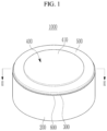
- FIG. 1 illustrates a perspective view showing a button cell according to an embodiment
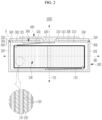
- FIG. 2 illustrates a cross-sectional view taken along the line II-II of FIG. 1 .
- a button cell 1000 which is a rechargeable battery capable of charging and discharging, includes an electrode assembly 100, a case 200, a cap plate 300, a terminal plate 400, a bonding layer 500, and a side welded portion 600.
- the electrode assembly 100 is accommodated in the case 200.
- a lower portion of the electrode assembly 100 faces a bottom portion of the case 200, and an upper portion of the electrode assembly 100 faces the terminal plate 400 and the cap plate 300 covering an opening 210 of the case 200.
- upper and lower portions of the electrode assembly 100 may have planes parallel to each other, but the present disclosure is not limited thereto.
- the electrode assembly 100 includes a first electrode 110, a second electrode 120, a separator 130, a first electrode tab 140, and a second electrode tab 150.
- the first electrode 110 and the second electrode 120 are spaced apart from each other, and a separator 130 including an insulating material is positioned between the first electrode 110 and the second electrode 120.
- the first electrode 110 may be an anode
- the second electrode 120 may be a cathode, but the present disclosure is not limited thereto, and, in another embodiment, the first electrode 110 may be the cathode, and the second electrode 120 may be the anode.
- the first electrode 110 has a band shape extending in a direction, and includes an anode coated region, which is an area where an anode active material layer is applied to a current collector of a metal foil (e.g., a Cu foil), and an anode uncoated region, which is a region where no active material is applied.
- the anode uncoated region may be positioned at an end of the first electrode 110 in an extension direction.
- the second electrode 120 has a band shape extending in a direction while being spaced apart from the first electrode 110 with the separator 130 provided therebetween, and includes a cathode coated region, which is a region where a cathode active material layer is applied to a current collector of a metal foil (e.g., an Al foil), and a cathode uncoated region, which is a region where no active material is applied.
- the cathode uncoated region may be positioned at an end of the second electrode 120 in an extension direction.
- the separator 130 extends in a direction between the first electrode 110 and the second electrode 120 to prevent or substantially prevent a short circuit between the first electrode 110 and the second electrode 120.
- the first electrode 110, the separator 130, and the second electrode 120 are sequentially stacked and wound to have a jelly roll shape with a vertical direction VD as a center thereof, but the present disclosure is not limited thereto, and the first electrode 110, the separator 130, and the second electrode 120 may be formed in any of various known shapes.
- the vertical direction VD includes, but is not limited to, a thickness direction of the button cell 1000.
- the first electrode tab 140 extends from the first electrode 110 of the electrode assembly 100 to a bottom portion of the case 200.
- the first electrode tab 140 is coupled to the bottom portion of the case 200 to connect the first electrode 110 and the case 200.
- the first electrode tab 140 is in contact with the first electrode 110 and the case 200.
- the first electrode tab 140 may be welded to the bottom portion of the case 200, but the present disclosure is not limited thereto, and the first electrode tab 140 may be in contact with the bottom portion of the case 200.
- the case 200 and the cap plate 300 have a same polarity as that of the first electrode 110 by the first electrode tab 140.
- the second electrode tab 150 extends from the second electrode 120 of the electrode assembly 100 to the terminal plate 400.
- the second electrode tab 150 is coupled to a protrusion 420 of the terminal plate 400 to connect the second electrode 120 and the terminal plate 400.
- the second electrode tab 150 is in contact with the second electrode 120 and the terminal plate 400.
- the second electrode tab 150 may be welded to a surface of the protrusion 420 of the terminal plate 400, but the present disclosure is not limited thereto, and may come into contact with the surface of the protrusion 420.
- the terminal plate 400 has a same polarity as that of the second electrode 120 by the second electrode tab 150.
- a center pin penetrating a center of the electrode assembly 100 in the vertical direction VD may be positioned at a central portion of the electrode assembly 100, and the center pin may support the first electrode tab 140 and the second electrode tab 150, but the present disclosure is not limited thereto.
- the case 200 is connected to the first electrode 110 of the electrode assembly 100 and accommodates the electrode assembly 100.
- the case 200 includes an opening 210 exposing the upper portion of the electrode assembly 100.
- the opening 210 of the case 200 may be formed by a sidewall 201 that is bent or extends in the vertical direction VD from the bottom portion of the case 200 to extend, but the present disclosure is not limited thereto.
- the case 200 may have a same polarity as that of the first electrode 110.
- the case 200 has a cylindrical can shape for accommodating the electrode assembly 100 having a form of a jelly roll, but the present disclosure is not limited thereto, and may have any of various known shapes.
- the case 200 may accommodate any of various known electrolyte solutions together with the electrode assembly 100.
- An outer surface of the case 200 and an outer surface of the cap plate 300 may be a first electrode terminal of the button cell 1000, but the present disclosure is not limited thereto.
- an upper surface of a flange portion 410 which is an outer surface of the terminal plate 400, may be a second electrode terminal of the button cell 1000, but the present disclosure is not limited thereto.
- a plating layer may be coated on an outer surface of the case 200, but the present disclosure is not limited thereto, and any of various well-known coating layers may be coated on the outer surface of the case 200.
- the case 200 may include stainless steel, but the present disclosure is not limited thereto, and may include any of various known metals.
- the opening 210 of the case 200 is covered by the cap plate 300 and the terminal plate 400.
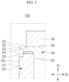
- FIG. 3 illustrates an enlarged view of a region "A" of FIG. 2 .
- the cap plate 300 is coupled to the case 200 to cover an outer area of the opening 210.
- the cap plate 300 includes a through hole 310 exposing a central region of the opening 210 and a step portion 320 welded to the sidewall 201 of the case 200.
- the through hole 310 is covered by the terminal plate 400, and the protrusion 420 of the terminal plate 400 extends through the through hole 310 to face the electrode assembly 100 accommodated in the case 200.
- the step portion 320 is recessed to correspond to the sidewall 201 of the case 200.
- the step portion 320 of the cap plate may have a thinner thickness in vertical direction VD compared to the thickness in vertical direction VD of the cap plate 300.
- the step portion 320 of the cap plate may have a length in horizontal direction HD, which corresponds to the thickness of the sidewall 201 of the case 200 in horizontal direction HD.
- the step portion 320 may be recessed from a rear surface 301 of the cap plate 300 facing the electrode assembly 100.
- the step portion 320 is recessed in a ring shape in a plan view along an edge 303 of the cap plate 300, but the present disclosure is not limited thereto.
- the sidewall 201 of the case 200 is inserted into the step portion 320.
- the edge 303 of the cap plate 300 covers (e.g., completely covers) the sidewall 201 of the case 200 in the vertical direction VD.
- the sidewall 201 of the case 200 is inserted into the step portion 320 of the cap plate 300 to allow the edge 303 of the cap plate 300 to cover (e.g., completely cover) the sidewall 201 of the case 200 in the vertical direction VD, and, thus, the sidewall 201 of the case 200 does not protrude in a horizontal direction HD, which is outside the edge 303 of the cap plate 300. Accordingly, the sidewall 201 of the case 200 is suppressed from being interfered with by another external element.
- the horizontal direction HD is a direction crossing the vertical direction VD and is a radial direction of the button cell 1000.
- the step portion 320 and the sidewall 201 are directly coupled by the side welded portion 600 formed by a side welding process using a welding means such as a laser beam irradiated in the horizontal direction HD in a state in which the sidewall 201 of the case 200 is inserted into the step portion 320 of the cap plate 300.
- the step portion 320 of the cap plate 300 and the sidewall 201 of the case 200 are directly coupled by the side welded portion 600, and, thus, an outer area of the opening 210 of the case 200 is covered by the cap plate 300.
- the cap plate 300 has a ring shape by the through-hole 310 formed in the center, but the present disclosure is not limited thereto.
- the cap plate 300 is coupled to the case 200 by the side welded portion 600 to have a same polarity as that of the first electrode 110. Accordingly, the cap plate 300 and the case 200 have the same polarity as that of the first electrode 110.
- the outer surface of the cap plate 300 may be a first electrode terminal of the button cell 1000, but the present disclosure is not limited thereto.
- the cap plate 300 is insulatingly bonded to the terminal plate 400 with the bonding layer 500 positioned on a front surface 302 of the cap plate 300, which is opposite to the rear surface 301 of the cap plate 300, provided therebetween.
- the cap plate 300 includes stainless steel, but the present disclosure is not limited thereto, and the cap plate 300 may include any of various known metals.
- the terminal plate 400 is connected to the second electrode 120 to be insulated from and bonded to the cap plate 300 by the bonding layer 500.
- the terminal plate 400 covers the through hole 310 of the cap plate 300.
- the terminal plate 400 is positioned on the front surface 302 of the cap plate 300.
- the terminal plate 400 covers a central area of the opening 210 of the case 200 exposed by the through hole 310 of the cap plate 300. Since the terminal plate 400 covers the central area of the opening 210 and the cap plate 300 covers an outer area of the opening 210, the opening 210 of the case 200 is completely covered by the terminal plate 400 and the cap plate 300.
- the terminal plate 400 firmly seals the electrode assembly 100 together with the case 200, the cap plate 300, and the bonding layer 500.
- the terminal plate 400 is coupled to the second electrode tab 150 of the electrode assembly 100 to be connected to the second electrode 120 of the electrode assembly 100.
- the terminal plate 400 has a same polarity as that of the second electrode 120.
- the terminal plate 400 includes the flange portion 410 and the protrusion 420.
- the flange portion 410 is positioned on the cap plate 300, and overlaps the cap plate 300 to cover the through hole 310.
- the flange portion 410 has a larger area than that of the protrusion 420.
- the flange portion 410 may have a larger diameter than that of the protrusion 420.
- the flange portion 410 has a thinner thickness than that of the protrusion 420, but the present disclosure is not limited thereto.
- a rear surface of the flange portion 410 contacts the bonding layer 500, and the flange portion 410 is insulatively bonded to the cap plate 300 by the bonding layer 500.
- a front surface of the flange portion 410 may be a second electrode terminal of the button cell 1000.
- the protrusion 420 protrudes from the flange portion 410 to extend through the through hole 310.
- the protrusion 420 is connected to the second electrode 120 through the through hole 310 from the flange portion 410.
- a surface of the protrusion 420 is coupled to the second electrode tab 150.
- the surface of the protrusion 420 may be welded to the second electrode tab 150, but the present disclosure is not limited thereto.
- the protrusion 420 and the flange portion 410 of the terminal plate 400 have a same polarity as that of the second electrode 120.
- the surface of the protrusion 420 coupled with the second electrode tab 150 may have a smaller diameter than that of the front surface of the flange portion 410, which may be an electrode terminal.
- the protrusion 420 and the flange portion 410 are integrally formed using a forging process, but the present disclosure is not limited thereto, and different materials may be combined to form the terminal plate 400.
- a plating layer may be coated on the outer surface of the terminal plate 400, but the present disclosure is not limited thereto, and various known coating layers may be coated on the outer surface of the terminal plate 400.
- the terminal plate 400 includes aluminum, but the present disclosure is not limited thereto, and the terminal plate 400 may include any of various known metals.
- the bonding layer 500 is positioned between the cap plate 300 and the flange portion 410 of the terminal plate 400.
- the bonding layer 500 insulates and bonds between the cap plate 300 and the terminal plate 400.
- the bonding layer 500 protrudes from the terminal plate 400 toward the step portion 320 of the cap plate 300.
- the bonding layer 500 protrudes in the horizontal direction HD from between the cap plate 300 and the terminal plate 400 to be exposed on the front surface 302 of the cap plate 300.
- the bonding layer 500 protrudes from the terminal plate 400 in the horizontal direction HD, which is a direction of the step portion 320 of the cap plate 300, and overlaps the step portion 320 in the vertical direction VD.
- the bonding layer 500 may include an insulating material and insulates between the cap plate 300 and the terminal plate 400.
- the bonding layer is (electrically) insulative and positioned between the cap plate and the terminal plate, and is configured to bind the cap plate and the terminal plate.
- the bonding layer 500 is thermally fused between the cap plate 300 and the flange portion 410 of the terminal plate 400 by using heat or a laser beam.
- the bonding layer 500 includes, but is not limited to, polypropylene, polyimide, etc., and may include any of various known resins for insulative bonding between the cap plate 300 and the terminal plate 400.
- the bonding layer 500 may include a thermosetting resin and a thermoplastic resin.
- the thermosetting resin and the thermoplastic resin of the bonding layer 500 may be stacked to include a plurality of layers, but the present disclosure is not limited thereto.
- the thermosetting resin of the bonding layer 500 is cured by heat, and may include any of various known thermosetting resins, such as a phenol resin, a urea resin, a melamine resin, an epoxy resin, and a polyester resin.
- the thermoplastic resin of the bonding layer 500 includes, but is not limited to, a polypropylene resin that melts at a certain temperature (e.g., a predetermined temperature), and may include any of various known thermoplastic resins, such as polystyrene, polyethylene, and a polyvinyl chloride resin.
- the side welded portion 600 welds and couples the cap plate 300 and the case 200.
- the annular side welded portion 600 welds between the step portion 320 of the cap plate 300 and the sidewall 201 of the case 200 inserted into the step portion 320.
- the side welded portion 600 is formed between the step portion 320 of the cap plate 300 and the sidewall 201 of the case 200 by using a welding means, such as a laser beam, irradiated in the horizontal direction HD.
- the side welded portion 600 has a circular ring shape along a planar shape of the step portion 320 of the cap plate 300 and the sidewall 201 of the case 200, but the present disclosure is not limited thereto, and, corresponding to planar shapes of the step portion 320 of the cap plate 300 and the sidewall 201 of the case 200, the side welded portion 600 may have any of various ring shapes, such as a polygonal shape, an elliptical shape, or a closed loop shape.
- a welding means such as a laser beam
- buttons cell according to another embodiment will be described with respect to differences from the button cell according to the above-described embodiment.
- FIG. 4 illustrates a cross-sectional view showing a portion of a button cell corresponding to the region "A" of FIG. 2 , according to another embodiment.
- buttons cell according to another embodiment will be described with respect to differences from the button cell according to the above-described embodiments.
- FIG. 5 illustrates a cross-sectional view showing a portion of a button cell corresponding to the region "A" of FIG. 2 , according to another embodiment.
- the side welded portion 600 welding between the step portion 320 of the cap plate 300 and the sidewall 201 of the case 200 is positioned inside the first welding groove 220 of the case 200 recessed from the outer surface 201a of the sidewall 201 of the case 200 and the second welding groove 330 of the cap plate 300 recessed from the surface of the edge 303 of the cap plate 300, and, thus, during a side welding process, an area to be welded by the first welding groove 220 and the second welding groove 330 may be easily checked, such that welding between the case 200 and the cap plate 300 may be easily performed by the side welded portion 600, and even when the side welded portion 600 protrudes from inside of the first welding groove 220 and the second welding groove 330 by the welding process, external interference may be suppressed.
Landscapes
- Chemical & Material Sciences (AREA)
- Chemical Kinetics & Catalysis (AREA)
- Electrochemistry (AREA)
- General Chemical & Material Sciences (AREA)
- Engineering & Computer Science (AREA)
- Manufacturing & Machinery (AREA)
- Sealing Battery Cases Or Jackets (AREA)
- Connection Of Batteries Or Terminals (AREA)
Applications Claiming Priority (1)
| Application Number | Priority Date | Filing Date | Title |
|---|---|---|---|
| KR1020230002444A KR20240110400A (ko) | 2023-01-06 | 2023-01-06 | 버튼 전지 |
Publications (1)
| Publication Number | Publication Date |
|---|---|
| EP4398355A1 true EP4398355A1 (fr) | 2024-07-10 |
Family
ID=88779495
Family Applications (1)
| Application Number | Title | Priority Date | Filing Date |
|---|---|---|---|
| EP23208775.9A Pending EP4398355A1 (fr) | 2023-01-06 | 2023-11-09 | Pile bouton |
Country Status (4)
| Country | Link |
|---|---|
| US (1) | US20240234883A1 (fr) |
| EP (1) | EP4398355A1 (fr) |
| KR (1) | KR20240110400A (fr) |
| CN (1) | CN118315738A (fr) |
Families Citing this family (5)
| Publication number | Priority date | Publication date | Assignee | Title |
|---|---|---|---|---|
| USD1096608S1 (en) * | 2020-06-29 | 2025-10-07 | Zhuhai Cosmx Battery Co., Ltd. | Button cell |
| USD1093278S1 (en) * | 2021-01-25 | 2025-09-16 | Zhuhai Cosmx Battery Co., Ltd. | Battery |
| USD1104945S1 (en) * | 2021-02-23 | 2025-12-09 | Zhuhai Cosmx Battery Co., Ltd. | Battery |
| USD1119756S1 (en) * | 2024-08-15 | 2026-03-24 | Broadata Communications, Inc. | Battery pack for wireless cart |
| CN120998749B (zh) * | 2025-10-23 | 2026-04-07 | 浙江中贝能源科技有限公司 | 具有小投影面积的熔断器 |
Citations (4)
| Publication number | Priority date | Publication date | Assignee | Title |
|---|---|---|---|---|
| WO2021230250A1 (fr) * | 2020-05-13 | 2021-11-18 | 株式会社村田製作所 | Batterie secondaire et son procédé de fabrication |
| WO2021244618A1 (fr) * | 2020-06-03 | 2021-12-09 | 珠海冠宇电池股份有限公司 | Pile bouton et son procédé de fabrication, et dispositif électronique |
| WO2022080722A1 (fr) * | 2020-10-12 | 2022-04-21 | 주식회사 엘지에너지솔루션 | Batterie secondaire de type bouton |
| CN216563341U (zh) * | 2021-12-22 | 2022-05-17 | 珠海冠宇电池股份有限公司 | 电池及电子设备 |
Family Cites Families (2)
| Publication number | Priority date | Publication date | Assignee | Title |
|---|---|---|---|---|
| JP2000090893A (ja) * | 1998-09-17 | 2000-03-31 | Japan Storage Battery Co Ltd | 電池及び電池の製造方法 |
| CN111900276A (zh) * | 2020-08-28 | 2020-11-06 | 珠海冠宇电池股份有限公司 | 一种电池外壳及电池 |
-
2023
- 2023-01-06 KR KR1020230002444A patent/KR20240110400A/ko active Pending
- 2023-10-17 US US18/488,891 patent/US20240234883A1/en active Pending
- 2023-11-09 EP EP23208775.9A patent/EP4398355A1/fr active Pending
- 2023-12-29 CN CN202311850222.8A patent/CN118315738A/zh active Pending
Patent Citations (4)
| Publication number | Priority date | Publication date | Assignee | Title |
|---|---|---|---|---|
| WO2021230250A1 (fr) * | 2020-05-13 | 2021-11-18 | 株式会社村田製作所 | Batterie secondaire et son procédé de fabrication |
| WO2021244618A1 (fr) * | 2020-06-03 | 2021-12-09 | 珠海冠宇电池股份有限公司 | Pile bouton et son procédé de fabrication, et dispositif électronique |
| WO2022080722A1 (fr) * | 2020-10-12 | 2022-04-21 | 주식회사 엘지에너지솔루션 | Batterie secondaire de type bouton |
| CN216563341U (zh) * | 2021-12-22 | 2022-05-17 | 珠海冠宇电池股份有限公司 | 电池及电子设备 |
Also Published As
| Publication number | Publication date |
|---|---|
| CN118315738A (zh) | 2024-07-09 |
| KR20240110400A (ko) | 2024-07-15 |
| US20240234883A1 (en) | 2024-07-11 |
Similar Documents
| Publication | Publication Date | Title |
|---|---|---|
| EP4398355A1 (fr) | Pile bouton | |
| US11545709B2 (en) | Rechargeable battery | |
| EP4376144A1 (fr) | Pile bouton | |
| US20240291078A1 (en) | Button cell | |
| US20240113370A1 (en) | Button cell | |
| EP4418388A1 (fr) | Pile bouton | |
| CN113851689B (zh) | 可再充电电池 | |
| US20240170775A1 (en) | Button cell | |
| US20250046922A1 (en) | Rechargeable battery | |
| CN113922006B (zh) | 可再充电电池 | |
| US20220336897A1 (en) | Rechargeable battery | |
| EP4030538A1 (fr) | Batterie rechargeable | |
| KR20210156607A (ko) | 이차 전지 | |
| US20240347827A1 (en) | Button cell | |
| CN114342137B (zh) | 可再充电电池 | |
| US20260074382A1 (en) | Rechargeable battery |
Legal Events
| Date | Code | Title | Description |
|---|---|---|---|
| PUAI | Public reference made under article 153(3) epc to a published international application that has entered the european phase |
Free format text: ORIGINAL CODE: 0009012 |
|
| STAA | Information on the status of an ep patent application or granted ep patent |
Free format text: STATUS: REQUEST FOR EXAMINATION WAS MADE |
|
| 17P | Request for examination filed |
Effective date: 20231109 |
|
| AK | Designated contracting states |
Kind code of ref document: A1 Designated state(s): AL AT BE BG CH CY CZ DE DK EE ES FI FR GB GR HR HU IE IS IT LI LT LU LV MC ME MK MT NL NO PL PT RO RS SE SI SK SM TR |