EP4398376A1 - Système de batterie et système d'alimentation électrique - Google Patents
Système de batterie et système d'alimentation électrique Download PDFInfo
- Publication number
- EP4398376A1 EP4398376A1 EP22880217.9A EP22880217A EP4398376A1 EP 4398376 A1 EP4398376 A1 EP 4398376A1 EP 22880217 A EP22880217 A EP 22880217A EP 4398376 A1 EP4398376 A1 EP 4398376A1
- Authority
- EP
- European Patent Office
- Prior art keywords
- switch
- battery pack
- time period
- battery
- turned
- Prior art date
- Legal status (The legal status is an assumption and is not a legal conclusion. Google has not performed a legal analysis and makes no representation as to the accuracy of the status listed.)
- Pending
Links
Images





Classifications
-
- H—ELECTRICITY
- H01—ELECTRIC ELEMENTS
- H01M—PROCESSES OR MEANS, e.g. BATTERIES, FOR THE DIRECT CONVERSION OF CHEMICAL ENERGY INTO ELECTRICAL ENERGY
- H01M10/00—Secondary cells; Manufacture thereof
- H01M10/42—Methods or arrangements for servicing or maintenance of secondary cells or secondary half-cells
- H01M10/425—Structural combination with electronic components, e.g. electronic circuits integrated to the outside of the casing
- H01M10/4264—Structural combination with electronic components, e.g. electronic circuits integrated to the outside of the casing with capacitors
-
- H—ELECTRICITY
- H01—ELECTRIC ELEMENTS
- H01M—PROCESSES OR MEANS, e.g. BATTERIES, FOR THE DIRECT CONVERSION OF CHEMICAL ENERGY INTO ELECTRICAL ENERGY
- H01M10/00—Secondary cells; Manufacture thereof
- H01M10/42—Methods or arrangements for servicing or maintenance of secondary cells or secondary half-cells
- H01M10/44—Methods for charging or discharging
- H01M10/448—End of discharge regulating measures
-
- H—ELECTRICITY
- H01—ELECTRIC ELEMENTS
- H01M—PROCESSES OR MEANS, e.g. BATTERIES, FOR THE DIRECT CONVERSION OF CHEMICAL ENERGY INTO ELECTRICAL ENERGY
- H01M10/00—Secondary cells; Manufacture thereof
- H01M10/42—Methods or arrangements for servicing or maintenance of secondary cells or secondary half-cells
- H01M10/425—Structural combination with electronic components, e.g. electronic circuits integrated to the outside of the casing
-
- H—ELECTRICITY
- H01—ELECTRIC ELEMENTS
- H01M—PROCESSES OR MEANS, e.g. BATTERIES, FOR THE DIRECT CONVERSION OF CHEMICAL ENERGY INTO ELECTRICAL ENERGY
- H01M10/00—Secondary cells; Manufacture thereof
- H01M10/05—Accumulators with non-aqueous electrolyte
- H01M10/052—Li-accumulators
- H01M10/0525—Rocking-chair batteries, i.e. batteries with lithium insertion or intercalation in both electrodes; Lithium-ion batteries
-
- H—ELECTRICITY
- H01—ELECTRIC ELEMENTS
- H01M—PROCESSES OR MEANS, e.g. BATTERIES, FOR THE DIRECT CONVERSION OF CHEMICAL ENERGY INTO ELECTRICAL ENERGY
- H01M10/00—Secondary cells; Manufacture thereof
- H01M10/05—Accumulators with non-aqueous electrolyte
- H01M10/054—Accumulators with insertion or intercalation of metals other than lithium, e.g. with magnesium or aluminium
-
- H—ELECTRICITY
- H01—ELECTRIC ELEMENTS
- H01M—PROCESSES OR MEANS, e.g. BATTERIES, FOR THE DIRECT CONVERSION OF CHEMICAL ENERGY INTO ELECTRICAL ENERGY
- H01M10/00—Secondary cells; Manufacture thereof
- H01M10/42—Methods or arrangements for servicing or maintenance of secondary cells or secondary half-cells
- H01M10/44—Methods for charging or discharging
-
- H—ELECTRICITY
- H01—ELECTRIC ELEMENTS
- H01M—PROCESSES OR MEANS, e.g. BATTERIES, FOR THE DIRECT CONVERSION OF CHEMICAL ENERGY INTO ELECTRICAL ENERGY
- H01M10/00—Secondary cells; Manufacture thereof
- H01M10/42—Methods or arrangements for servicing or maintenance of secondary cells or secondary half-cells
- H01M10/44—Methods for charging or discharging
- H01M10/441—Methods for charging or discharging for several batteries or cells simultaneously or sequentially
-
- H—ELECTRICITY
- H01—ELECTRIC ELEMENTS
- H01M—PROCESSES OR MEANS, e.g. BATTERIES, FOR THE DIRECT CONVERSION OF CHEMICAL ENERGY INTO ELECTRICAL ENERGY
- H01M10/00—Secondary cells; Manufacture thereof
- H01M10/42—Methods or arrangements for servicing or maintenance of secondary cells or secondary half-cells
- H01M10/46—Accumulators structurally combined with charging apparatus
-
- H—ELECTRICITY
- H01—ELECTRIC ELEMENTS
- H01M—PROCESSES OR MEANS, e.g. BATTERIES, FOR THE DIRECT CONVERSION OF CHEMICAL ENERGY INTO ELECTRICAL ENERGY
- H01M10/00—Secondary cells; Manufacture thereof
- H01M10/42—Methods or arrangements for servicing or maintenance of secondary cells or secondary half-cells
- H01M10/48—Accumulators combined with arrangements for measuring, testing or indicating the condition of cells, e.g. the level or density of the electrolyte
-
- H—ELECTRICITY
- H01—ELECTRIC ELEMENTS
- H01M—PROCESSES OR MEANS, e.g. BATTERIES, FOR THE DIRECT CONVERSION OF CHEMICAL ENERGY INTO ELECTRICAL ENERGY
- H01M10/00—Secondary cells; Manufacture thereof
- H01M10/42—Methods or arrangements for servicing or maintenance of secondary cells or secondary half-cells
- H01M10/48—Accumulators combined with arrangements for measuring, testing or indicating the condition of cells, e.g. the level or density of the electrolyte
- H01M10/486—Accumulators combined with arrangements for measuring, testing or indicating the condition of cells, e.g. the level or density of the electrolyte for measuring temperature
-
- H—ELECTRICITY
- H01—ELECTRIC ELEMENTS
- H01M—PROCESSES OR MEANS, e.g. BATTERIES, FOR THE DIRECT CONVERSION OF CHEMICAL ENERGY INTO ELECTRICAL ENERGY
- H01M10/00—Secondary cells; Manufacture thereof
- H01M10/60—Heating or cooling; Temperature control
- H01M10/61—Types of temperature control
- H01M10/615—Heating or keeping warm
-
- H—ELECTRICITY
- H01—ELECTRIC ELEMENTS
- H01M—PROCESSES OR MEANS, e.g. BATTERIES, FOR THE DIRECT CONVERSION OF CHEMICAL ENERGY INTO ELECTRICAL ENERGY
- H01M10/00—Secondary cells; Manufacture thereof
- H01M10/60—Heating or cooling; Temperature control
- H01M10/62—Heating or cooling; Temperature control specially adapted for specific applications
- H01M10/625—Vehicles
-
- H—ELECTRICITY
- H01—ELECTRIC ELEMENTS
- H01M—PROCESSES OR MEANS, e.g. BATTERIES, FOR THE DIRECT CONVERSION OF CHEMICAL ENERGY INTO ELECTRICAL ENERGY
- H01M10/00—Secondary cells; Manufacture thereof
- H01M10/60—Heating or cooling; Temperature control
- H01M10/63—Control systems
-
- H—ELECTRICITY
- H02—GENERATION; CONVERSION OR DISTRIBUTION OF ELECTRIC POWER
- H02J—ELECTRIC POWER NETWORKS; CIRCUIT ARRANGEMENTS OR SYSTEMS FOR SUPPLYING OR DISTRIBUTING ELECTRIC POWER; SYSTEMS FOR STORING ELECTRIC ENERGY
- H02J7/00—Circuit arrangements for charging or discharging batteries or for supplying loads from batteries
- H02J7/865—Battery or charger load switching, e.g. concurrent charging and load supply
-
- H—ELECTRICITY
- H02—GENERATION; CONVERSION OR DISTRIBUTION OF ELECTRIC POWER
- H02J—ELECTRIC POWER NETWORKS; CIRCUIT ARRANGEMENTS OR SYSTEMS FOR SUPPLYING OR DISTRIBUTING ELECTRIC POWER; SYSTEMS FOR STORING ELECTRIC ENERGY
- H02J7/00—Circuit arrangements for charging or discharging batteries or for supplying loads from batteries
- H02J7/90—Regulation of charging or discharging current or voltage
- H02J7/971—Regulation of charging or discharging current or voltage the charge cycle being controlled or terminated in response to non-electric parameters
- H02J7/975—Regulation of charging or discharging current or voltage the charge cycle being controlled or terminated in response to non-electric parameters in response to temperature
- H02J7/977—Regulation of charging or discharging current or voltage the charge cycle being controlled or terminated in response to non-electric parameters in response to temperature of the battery
-
- H—ELECTRICITY
- H01—ELECTRIC ELEMENTS
- H01M—PROCESSES OR MEANS, e.g. BATTERIES, FOR THE DIRECT CONVERSION OF CHEMICAL ENERGY INTO ELECTRICAL ENERGY
- H01M10/00—Secondary cells; Manufacture thereof
- H01M10/42—Methods or arrangements for servicing or maintenance of secondary cells or secondary half-cells
- H01M10/46—Accumulators structurally combined with charging apparatus
- H01M10/465—Accumulators structurally combined with charging apparatus with solar battery as charging system
-
- H—ELECTRICITY
- H01—ELECTRIC ELEMENTS
- H01M—PROCESSES OR MEANS, e.g. BATTERIES, FOR THE DIRECT CONVERSION OF CHEMICAL ENERGY INTO ELECTRICAL ENERGY
- H01M10/00—Secondary cells; Manufacture thereof
- H01M10/42—Methods or arrangements for servicing or maintenance of secondary cells or secondary half-cells
- H01M10/425—Structural combination with electronic components, e.g. electronic circuits integrated to the outside of the casing
- H01M2010/4271—Battery management systems including electronic circuits, e.g. control of current or voltage to keep battery in healthy state, cell balancing
-
- H—ELECTRICITY
- H01—ELECTRIC ELEMENTS
- H01M—PROCESSES OR MEANS, e.g. BATTERIES, FOR THE DIRECT CONVERSION OF CHEMICAL ENERGY INTO ELECTRICAL ENERGY
- H01M2220/00—Batteries for particular applications
- H01M2220/10—Batteries in stationary systems, e.g. emergency power source in plant
-
- H—ELECTRICITY
- H01—ELECTRIC ELEMENTS
- H01M—PROCESSES OR MEANS, e.g. BATTERIES, FOR THE DIRECT CONVERSION OF CHEMICAL ENERGY INTO ELECTRICAL ENERGY
- H01M2220/00—Batteries for particular applications
- H01M2220/20—Batteries in motive systems, e.g. vehicle, ship, plane
-
- H—ELECTRICITY
- H02—GENERATION; CONVERSION OR DISTRIBUTION OF ELECTRIC POWER
- H02J—ELECTRIC POWER NETWORKS; CIRCUIT ARRANGEMENTS OR SYSTEMS FOR SUPPLYING OR DISTRIBUTING ELECTRIC POWER; SYSTEMS FOR STORING ELECTRIC ENERGY
- H02J2207/00—Details of circuit arrangements for charging or discharging batteries or supplying loads from batteries
- H02J2207/20—Charging or discharging characterised by the power electronics converter
-
- Y—GENERAL TAGGING OF NEW TECHNOLOGICAL DEVELOPMENTS; GENERAL TAGGING OF CROSS-SECTIONAL TECHNOLOGIES SPANNING OVER SEVERAL SECTIONS OF THE IPC; TECHNICAL SUBJECTS COVERED BY FORMER USPC CROSS-REFERENCE ART COLLECTIONS [XRACs] AND DIGESTS
- Y02—TECHNOLOGIES OR APPLICATIONS FOR MITIGATION OR ADAPTATION AGAINST CLIMATE CHANGE
- Y02E—REDUCTION OF GREENHOUSE GAS [GHG] EMISSIONS, RELATED TO ENERGY GENERATION, TRANSMISSION OR DISTRIBUTION
- Y02E60/00—Enabling technologies; Technologies with a potential or indirect contribution to GHG emissions mitigation
- Y02E60/10—Energy storage using batteries
Definitions
- Duration of the first cycle, a quantity of first cycles, duration of the second cycle, and a quantity of second cycles are determined by the battery parameters and the voltage and the current limit value of the DC/DC conversion unit, and the charge/discharge current limit value may be determined by the battery parameters (for example, a battery voltage and a battery temperature).
- the at least one consecutive first cycle may be earlier or later than the at least one consecutive second cycle. This may be specifically determined based on an actual application scenario, and is not limited herein.
- the average charge/discharge current value may indicate a difference between discharge energy of the battery pack in the at least one consecutive first cycle and charge energy of the battery pack in the at least one consecutive second cycle.
- the charge/discharge current limit value may include a charge current limit value (that is, a maximum charge current) or a discharge current limit value (that is, a maximum discharge current).
- the battery pack When the average charge/discharge current value is less than or equal to the charge current limit value (that is, the discharge energy is less than the charge energy), the battery pack can be charged while the battery pack is heated (that is, the battery pack is in a heating and charging state). When the average charge/discharge current value is less than or equal to the discharge current limit value (that is, the discharge energy is greater than the charge energy), discharging of the battery pack can be controlled while the battery pack is heated (that is, the battery pack is in a heating and discharging state).
- the battery pack when the battery pack is in a safe state (that is, the average charge/discharge current value is less than or equal to the charge/discharge current limit value), the battery pack can be fast charged and discharged to the maximum extent, to ensure energy maximization, higher energy utilization, higher safety, and high applicability.
- the sampling control unit may be configured to obtain a switching duty cycle and a switching frequency of each of a plurality of switches in each DC/DC conversion circuit based on the battery parameters and the voltage and the current limit value that are of the DC/DC conversion unit.
- the sampling control unit may control turn-on or turn-off of each switch in each DC/DC conversion circuit based on the switching duty cycle and the switching frequency of each of the first switch and the second switch in the DC/DC conversion circuit, to fast charge and discharge the battery pack in the at least one consecutive first cycle and the at least one consecutive second cycle. In this way, heating efficiency and a heating speed of the battery pack are improved, and energy utilization is high.
- the second cycle includes a first charging time period and a second charging time period later than the first charging time period.
- the sampling control unit may be configured to: based on the switching duty cycle and the switching frequency of each switch, control, in the first charging time period, the first switch to be turned off and the second switch to be turned on, and control, in the second charging time period, the second switch to be turned off and the first switch to be turned on, to fast charge the battery pack.
- the DC/DC conversion circuit when the circuit topology of the DC/DC conversion circuit is the bidirectional DC/DC H-bridge circuit, the DC/DC conversion circuit includes a fifth switch, a sixth switch, a seventh switch, an eighth switch, and a third inductor; the energy storage unit includes a capacitor; the fifth switch and the sixth switch may be connected in series and then connected in parallel to the battery pack; the seventh switch and the eighth switch may be connected in series and then connected in parallel to the capacitor; and a series connection point of the fifth switch and the sixth switch may be connected to a series connection point of the seventh switch and the eighth switch by using the third inductor.
- the fifth switch and the sixth switch are alternately turned on.
- the sampling control unit may control turn-on or turn-off of each switch in each DC/DC conversion circuit based on the switching duty cycle and the switching frequency of each of the fifth switch, the sixth switch, the seventh switch, and the eighth switch in the DC/DC conversion circuit, to fast charge and discharge the battery pack in the at least one consecutive first cycle and the at least one consecutive second cycle. In this way, heating efficiency and a heating speed of the battery pack are improved, and energy utilization is high.
- the first cycle includes a first discharging time period, a second discharging time period, and a third discharging time period, the first discharging time period is earlier than the second discharging time period, and the second discharging time period is earlier than the third discharging time period.
- the second cycle includes a first charging time period, a second charging time period, and a third charging time period, the first charging time period is earlier than the second charging time period, and the second charging time period is earlier than the third charging time period.
- the sampling control unit may be configured to: based on the switching duty cycle and the switching frequency of each switch, control, in the first charging time period, the fifth switch and the eighth switch to be turned off and the sixth switch and the seventh switch to be turned on; control, in the second charging time period, the sixth switch and the eighth switch to be turned off and the fifth switch and the seventh switch to be turned on; and control, in the third charging time period, the sixth switch and the seventh switch to be turned off and the fifth switch and the eighth switch to be turned on, to fast charge the battery pack.
- this application provides a power supply system.
- the power supply system includes a DC/DC conversion module and at least one battery system provided in any one of the first aspect to the eleventh possible implementation of the first aspect. Battery systems may be connected in parallel and then connected to the DC/DC conversion module.
- the battery system can still work normally in a low-temperature environment. In this way, power supply efficiency of the system is improved, and applicability is high.
- the power supply system further includes a power supply module and a power conversion module connected to the power supply module.
- the power supply module includes a photovoltaic array, and the power conversion module may be a DC/DC conversion module.
- the power supply module includes a generator, and the power conversion module may be an alternating current (alternating current, AC)/DC conversion module.
- the power supply system further includes a direct current bus and a DC/AC conversion module, the DC/DC conversion module and the power conversion module may be separately connected to an input end of the DC/AC conversion module through the direct current bus, and an output end of the DC/AC conversion module may be connected to an alternating current load or an alternating current power grid.
- the power supply system may further include an on-grid/off-grid connection box, and the output end of the DC/AC conversion module may be connected to the alternating current load or the alternating current power grid by using the on-grid/off-grid connection box.
- a specific connection manner between functional modules in the power supply system provided in this application may be determined based on an actual application scenario. This is not limited herein.
- the battery pack can be fast charged and discharged in the at least one consecutive first cycle and the at least one consecutive second cycle, to perform pulse heating on the battery pack. This avoids a lithium precipitation phenomenon, and reduces a risk of a battery short circuit.
- the battery pack is self-heated from inside to outside by using a Joule thermal effect of the battery pack, to uniformly heat the battery pack. In this way, heating efficiency is improved, a heating speed is higher, a system structure is simple, costs are low, and applicability is high.
- a battery system provided in this application is applicable to a plurality of application fields such as the new energy intelligent microgrid field, the power transmission and distribution field, the new energy field (for example, the photovoltaic on-grid field or the wind on-grid field), the photovoltaic energy storage and power generation field (for example, power supply to an electric device (for example, a refrigerator or an air conditioner) or a power grid), the wind energy storage and power generation field, or the high-power converter field (for example, converting a direct current into a high-power high-voltage alternating current).
- the new energy field for example, the photovoltaic on-grid field or the wind on-grid field
- the photovoltaic energy storage and power generation field for example, power supply to an electric device (for example, a refrigerator or an air conditioner) or a power grid
- the wind energy storage and power generation field for example, converting a direct current into a high-power high-voltage alternating current.
- This may be specifically determined based on an actual application scenario
- the battery system provided in this application may be adapted to different application scenarios, for example, an application scenario of photovoltaic energy storage and power supply, an application scenario of wind energy storage and power supply, an application scenario of energy storage and power supply, or another application scenario.
- application scenario of energy storage and power supply for example, an application scenario of photovoltaic energy storage and power supply, an application scenario of wind energy storage and power supply, an application scenario of energy storage and power supply, or another application scenario.
- the following uses the application scenario of energy storage and power supply as an example for description, and details are not described below again.
- FIG. 1 is a schematic diagram of an application scenario of a battery system according to this application.
- the power supply system includes a battery system and a DC/AC converter.
- the battery system includes a battery pack and a battery management system.
- the battery pack may be connected to the DC/AC converter by using the battery management system.
- the battery management system may convert a direct current voltage provided by the battery pack into a target direct current voltage, and output the target direct current voltage to the DC/AC converter.
- the DC/AC converter may convert the target direct current voltage input by the battery management system into an alternating current voltage, and supply power to a power grid and an electric device based on the alternating current voltage.
- the DC/AC converter may convert the target direct current voltage input by the battery management system into an alternating current voltage, and supply power to a power grid and an electric device based on the alternating current voltage.
- FIG. 1 when the battery system is in a low-temperature environment, because a discharge capacity of the battery pack is reduced due to an excessively low temperature, a lithium dendrite is formed on a diaphragm of the battery pack when the battery pack is charged, and consequently, thermal runaway of the battery pack is caused, and the power supply system cannot work normally. Therefore, charging and discharging of the battery pack in the low-temperature environment are particularly important.
- the battery management system may fast charge and discharge the battery pack by using an internal circuit, to heat the battery pack to enable the battery pack to work normally, so as to avoid thermal runaway of the battery pack, improve heating efficiency of the battery pack, further improve power supply efficiency of the power supply system, and improve applicability.
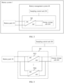
- FIG. 2 is a schematic structural diagram of a battery system according to this application.
- the battery system 1 includes a battery pack 10 (which may also be referred to as an electrochemical cell pack) and a battery management system 20.
- the battery management system 20 may be connected to the battery pack 10 to perform charging and discharging control on the battery pack 10.
- the battery pack 10 may include but is not limited to a plurality of secondary batteries such as a lithium-ion battery and a sodium-ion battery.
- the battery pack 10 and the battery management system 20 herein may form a battery module, and may be applied to a plurality of battery use fields such as the communication field (for example, a communication and energy storage battery) and the electric vehicle field (for example, a power battery).
- the battery management system 20 may include a sampling control unit 201, a DC/DC conversion unit 202, and an energy storage unit 203.
- the DC/DC conversion unit 202 and the energy storage unit 203 may be connected in parallel.
- the battery management system 20 herein may be a board integrated with the sampling control unit 201, the DC/DC conversion unit 202, and the energy storage unit 203.
- one or more functional modules that are in the battery management system and that are configured to collect data and control the DC/DC conversion unit may be collectively referred to as a sampling control unit, for example, a controller (micro controller unit, MCU for short).
- the sampling control unit 201 may collect a battery temperature of the battery pack 10 in real time by using a temperature monitor, and when the battery temperature is greater than a preset temperature threshold, determine that the battery pack 10 does not need to be heated.
- the preset temperature threshold herein may be a battery temperature that is preset when the battery pack needs to be heated, heated and charged, or heated and discharged.
- the preset temperature threshold may be determined by an electrochemical cell material of the battery pack 10 and a state (for example, a charging/discharging state or an offline state) of the battery pack 10.
- the sampling control unit 201 may control switching transistors in the DC/DC conversion unit 202 to be synchronously turned off, or reduce a negative current in the DC/DC conversion unit 202, or increase a switching frequency of a switch in the DC/DC conversion unit 202, so that a switching loss in a charging/discharging condition can be reduced, and applicability is higher.
- the sampling control unit 201 determines that the battery pack 10 needs to be heated.
- the battery pack 10 is fast charged or discharged to heat the battery pack 10.
- the at least one consecutive first cycle may be earlier or later than the at least one consecutive second cycle. This may be specifically determined based on an actual application scenario, and is not limited herein.
- Duration of the first cycle, a quantity of first cycles, duration of the second cycle, and a quantity of second cycles may be determined by the battery parameters and the voltage and the current limit value of the DC/DC conversion unit 202.
- the current limit value herein may be understood as a maximum current that can be borne by the DC/DC conversion unit 202.
- the maximum current is a limit value of a current that can be borne by the DC/DC conversion unit 202 in a safe state without affecting the DC/DC conversion unit 202, and may be determined by a specific circuit topology of the DC/DC conversion unit 202.
- the battery parameters may include but are not limited to a battery voltage, a battery temperature, and a current required for heating the battery pack 10 (that is, a heating requirement capability of the battery pack 10).
- a difference between a battery voltage and the voltage of the DC/DC conversion unit 202, an inductance amount corresponding to an inductor in the DC/DC conversion unit 202, and another parameter may also determine the quantity of first cycles, the duration of the first cycle, the quantity of second cycles, and the duration of the second cycle.
- the sampling control unit 201 may fast charge and discharge the battery pack 10 in the at least one consecutive first cycle and the at least one consecutive second cycle, to perform pulse heating on the battery pack 10. This avoids a lithium precipitation phenomenon, and reduces a risk of a battery short circuit.
- the battery pack 10 is self-heated from inside to outside by using a Joule thermal effect of the battery pack 10, to uniformly heat the battery pack 10. In this way, heating efficiency is improved, a heating speed is higher, a system structure is simple, and costs are lower.
- the sampling control unit 201 may fast charge and discharge the battery pack 10 to the maximum extent, to ensure energy maximization, higher energy utilization, higher safety, and higher applicability.
- the average charge/discharge current value may indicate a difference between discharge energy of the battery pack 10 in the at least one consecutive first cycle and charge energy of the battery pack 10 in the at least one consecutive second cycle.
- the charge/discharge current limit value of the battery pack 10 may be determined by the battery parameters (for example, the battery temperature and the battery voltage) of the battery pack 10, and the charge/discharge current limit value may include a charge current limit value (that is, a maximum charge current) or a discharge current limit value (that is, a maximum discharge current).
- the sampling control unit 201 may control, based on the battery parameters of the battery pack 10 and the voltage and the current limit value of the DC/DC conversion unit 202, the average charge/discharge current value to be equal to 0 (that is, the charge/discharge current limit value is 0, and the discharge energy is equal to the charge energy), to heat the battery pack 10 (that is, the battery pack 10 is in a heating state).
- the sampling control unit 201 may control, based on the battery parameters of the battery pack 10 and the voltage and the current limit value of the DC/DC conversion unit 202, the average charge/discharge current value to be less than or equal to the discharge current limit value (that is, the discharge energy is greater than the charge energy), so that the battery pack 10 can be controlled to discharge while the battery pack 10 is heated (that is, the battery pack 10 is in a heating and discharging state).
- the sampling control unit 201 may heat the battery pack 10, charge the battery pack 10 while heating the battery pack 10, or control discharging of the battery pack 10 when heating the battery pack 10, to improve a charging rate and a power backup capability of the battery pack in a low-temperature environment, and reduce system application costs.
- the battery pack 10 when the battery pack 10 is in a safe state, the battery pack 10 can be fast charged and discharged to the maximum extent, to ensure energy maximization, higher energy utilization, higher safety, and high applicability.
- the sampling control unit 201 may control, in each of the at least two consecutive first cycles, the battery pack 10 to discharge to the energy storage unit 203 by using the DC/DC conversion unit 202; control, in each of the at least two consecutive second cycles, the energy storage unit 203 to charge the battery pack 10 by using the DC/DC conversion unit 202; and control, in the at least two consecutive first cycles and the at least two consecutive second cycles, the average charge/discharge current value of the battery pack 10 to be less than or equal to the charge/discharge current limit value.
- the sampling control unit 201 may fast charge and discharge the battery pack 10 in the at least two consecutive first cycles and the at least two consecutive second cycles, so that a heating speed of the battery pack 10 is further improved while the battery pack 10 is uniformly heated, and heating efficiency is higher.
- the average charge/discharge current value of the battery pack 10 may be controlled to be less than or equal to the charge/discharge current limit value, to ensure energy maximization, higher energy utilization, and higher safety.
- the battery parameters of the battery pack 10 may include the battery voltage and the battery temperature.
- the battery system 1 may further include a temperature detector (not shown) and a voltage detector (not shown).
- the temperature detector and the voltage detector may separately communicate with the sampling control unit 201 to transmit temperature data (for example, the battery temperature) and voltage data (for example, the battery voltage).
- the temperature detector and the voltage detector may be directly integrated into the sampling control unit 201, and specific locations of the temperature detector and the voltage detector may be determined based on an actual application scenario.
- the temperature detector may collect the battery temperature of the battery pack 10 in real time
- the voltage detector may collect the battery voltage of the battery pack 10 in real time.
- the sampling control unit 201 may obtain a first charge/discharge current limit value of the battery pack 10 based on the battery voltage; obtain a second charge/discharge current limit value of the battery pack 10 based on the battery temperature; and obtain the charge/discharge current limit value of the battery pack 10 based on the smaller one of the first charge/discharge current limit value and the second charge/discharge current limit value.
- a case in which the battery parameters do not include the battery voltage may exist.
- the sampling control unit 201 may collect the battery temperature of the battery pack 10 in real time by using the temperature detector, obtain the first charge/discharge current limit value of the battery pack 10 based on the battery temperature, and use the first charge/discharge current limit value as the charge/discharge current limit value of the battery pack 10.
- the sampling control unit 201 may obtain the first charge/discharge current limit value from a prestored database based on the battery voltage, obtain the second charge/discharge current limit value from the prestored database based on the battery temperature, and use the smaller one of (that is, a smaller charge/discharge current limit value) of the two as the charge/discharge current limit value of the battery pack 10.
- the prestored database herein stores a correspondence between a battery voltage and a first charge/discharge current limit value and a correspondence between a battery temperature and a second charge/discharge current limit value.
- the first charge/discharge current limit value may include a first charge current limit value or a first discharge current limit value
- the second charge/discharge current limit value may include a second charge current limit value or a second discharge current limit value
- the charge/discharge current limit value includes the charge current limit value or the discharge current limit value.
- the sampling control unit 201 may use the smaller one of the first charge current limit value and the second charge current limit value as the charge current limit value, or use the smaller one of the first discharge current limit value and the second discharge current limit value as the discharge current limit value.
- the sampling control unit 201 may indirectly determine the charge/discharge current limit value (for example, the charge current limit value or the discharge current limit value) of the battery pack 10 based on the battery voltage and the battery temperature, so that the battery pack 10 can be fast charged and discharged to the maximum extent when the battery pack 10 is in a safe state, to ensure energy maximization, higher energy utilization, higher safety, and higher applicability.
- the charge/discharge current limit value for example, the charge current limit value or the discharge current limit value
- the DC/DC conversion unit 202 may include at least one DC/DC conversion circuit (that is, one or more DC/DC conversion circuits).
- FIG. 3 is another schematic structural diagram of a battery system according to this application. As shown in FIG. 3 , the DC/DC conversion unit 202 shown in FIG. 2 includes a DC/DC conversion circuit 2021 to a DC/DC conversion circuit 202n, first input/output ends of the DC/DC conversion circuit 2021 to the DC/DC conversion circuit 202n are connected in parallel and then connected to the battery pack 10, and second input/output ends of the DC/DC conversion circuit 2021 to the DC/DC conversion circuit 202n are connected in parallel and then connected to the energy storage unit 203.
- the DC/DC conversion unit 202 may further include a switching circuit, an AD/DC conversion circuit, and a corresponding auxiliary drive circuit. This may be specifically determined based on an actual application scenario, and is not limited herein.
- the first input/output ends of the DC/DC conversion circuit 2021 to the DC/DC conversion circuit 202n may be used as input ends, and the second input/output ends may be used as output ends.
- the first input/output ends of the DC/DC conversion circuit 2021 to the DC/DC conversion circuit 202n may be used as output ends, and the second input/output ends may be used as input ends.
- the sampling control unit 201 may also obtain a wave-emitting mode of and a wave-emitting coefficient of each switch based on the battery parameters and the voltage and the current limit value that are of the DC/DC conversion unit 202. This may be specifically determined based on an actual application scenario, and is not limited herein.
- the wave-emitting mode herein may include but is not limited to a square wave, a triangular wave, a trapezoidal wave (or an irregular trapezoidal wave), a sine wave, or a combination of the foregoing waveforms.
- FIG. 4 is another schematic structural diagram of a battery system according to this application.
- the DC/DC conversion circuit 2021 shown in FIG. 3 includes a first switch Q1, a second switch Q2, and a first inductor L1; the energy storage unit 203 shown in FIG.
- FIG. 5 is a schematic diagram of a discharge current flow direction of a battery system according to this application.
- the first cycle includes a first discharging time period and a second discharging time period later than the first discharging time period, as shown in 5a in FIG.
- the sampling control unit 201 may control, in a second discharging time period of the 1 st first cycle, the first switch Q1 to be turned off and the second switch Q2 to be turned on, so that the capacitor C0 may be charged through freewheeling of the first inductor L1, until the current of the first inductor L1 decreases to 0.
- the battery pack 10 can be controlled, in the 1 st first cycle, to discharge to the energy storage unit 203 by using the DC/DC conversion circuit 2021.
- FIG. 6 is a schematic diagram of a charge current flow direction of a battery system according to this application.
- the second cycle includes a first charging time period and a second charging time period later than the first charging time period, as shown in 6a in FIG.
- sampling control unit 201 controls charging of the battery pack 10 in the 2 nd second cycle to an N2 th second cycle
- the sampling control unit 201 controls charging of the battery pack 10 in the 1 st second cycle. Details are not described below again.
- the sampling control unit 201 may perform alternate control on the first switch Q1 and the second switch Q2 beyond dead time, so that a switching ripple current flows in and out of the battery pack 10 in the N1 consecutive first cycles and the N2 consecutive second cycles, to fast charge and discharge the battery pack 10.
- a time interval is extremely short and a frequency is high, and lithium ions do not accumulate on a battery SEI film. Therefore, a lithium precipitation phenomenon can be avoided, and a risk of a short circuit of the battery pack 10 is reduced.
- the average charge/discharge current value I00 of the battery pack 10 in a complete cycle that is, N1*(t1+t2)+N2*(t3+t4)) is 0.
- the average charge/discharge current value I10 of the battery pack 10 in a complete cycle (that is, N1*(t1+t2)+N2*(t3+t4)) is less than or equal to the charge current limit value. In this way, the battery pack 10 can be charged by using the average charge/discharge current value I10 while the battery pack 10 is heated.
- the average charge/discharge current value I00 of the battery pack 10 in a complete cycle that is, t1+t2+t3+t4) is 0. In this way, the battery pack 10 is heated.
- the average charge/discharge current value I00 of the battery pack 10 in each of the plurality of complete cycles (that is, t1+t2+t3+t4) is 0.
- FIG. 9 is another schematic structural diagram of a battery system according to this application.
- the DC/DC conversion circuit 2021 shown in FIG. 3 includes a third switch Q3, a fourth switch Q4, and a second inductor L2; the energy storage unit 203 shown in FIG.
- the preset current value herein may be determined by the battery parameters, the voltage and the current limit value of the DC/DC conversion unit 201, and an inductance amount of the second inductor L2.
- the sampling control unit 201 may control, in a second charging time period of the 1 st second cycle, the third switch Q3 to be turned off and the fourth switch Q4 to be turned on, so that the battery pack 10 is charged through freewheeling of the second inductor L2 until the current of the second inductor L2 decreases to 0.
- the energy storage unit 203 can be controlled, in the 1 st second cycle, to charge the battery pack 10 by using the DC/DC conversion circuit 2021.
- FIG. 11 is a schematic diagram of another discharge current flow direction of a battery system according to this application.
- the first cycle includes a first discharging time period and a second discharging time period later than the first discharging time period, as shown in 11a in FIG.
- the sampling control unit 201 may control, in a first discharging time period of the 1 st first cycle, the third switch Q3 to be turned off and the fourth switch Q4 to be turned on, so that the battery pack 10 can be boosted (boosted) by the fourth switch Q4 to discharge outwards, and the second inductor L2 stores energy (in this case, a current of the second inductor L2 increases in a negative direction), until the current of the second inductor L2 reaches a preset current value or the first discharging time period ends. After the second inductor L2 stores energy, as shown in 11b in FIG.
- the sampling control unit 201 may control, in a second discharging time period of the 1 st first cycle, the fourth switch Q4 to be turned off and the third switch Q3 to be turned on, so that the battery pack 10 and the second inductor L2 discharge, by using the third switch Q3, to the capacitor C0 and/or the external power supply connected to the input/output end, until the current of the second inductor L2 decreases to 0.
- the battery pack 10 can be controlled, in the 1 st first cycle, to discharge to the energy storage unit 203 by using the DC/DC conversion circuit 2021.
- the sampling control unit 201 may perform alternate control on the third switch Q3 and the fourth switch Q4 beyond dead time, and generate alternate and repeated pulse currents between the energy storage unit 203 and the battery pack 10, so that a self-heating function of the battery pack 10 can be implemented based on heat generated based on internal impedance of the battery pack 10, to further improve heating efficiency and a heating speed of the battery pack 10.
- the battery pack 10 may be further heated and charged or heated and discharged, so that a charging rate and a power backup capability of the battery pack 10 in a low-temperature environment are improved, and applicability is higher.
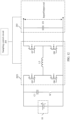
- the third inductor L3 includes a capacitor C0; the fifth switch Q5 and the sixth switch Q6 may be connected in series and then connected in parallel to the battery pack 10; the seventh switch Q7 and the eighth switch Q8 may be connected in series and then connected in parallel to the capacitor C0; and a series connection point of the fifth switch Q5 and the sixth switch Q6 may be connected to a series connection point between the seventh switch Q7 and the eighth switch Q8 by using the third inductor L3.
- the fifth switch Q5 and the sixth switch Q6 are alternately turned on. To be specific, when the fifth switch Q5 is turned on, the sixth switch Q6 is turned off, or when the fifth switch Q5 is turned off, the sixth switch Q6 is turned on. The seventh switch Q7 and the eighth switch Q8 are alternately turned on.
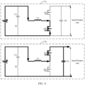
- FIG. 13 is a schematic diagram of another discharge current flow direction of a battery system according to this application.
- the first cycle includes a first discharging time period, a second discharging time period, and a third discharging time period
- the first discharging time period is earlier than the second discharging time period
- the second discharging time period is earlier than the third discharging time period, as shown in 13a in FIG.
- the sampling control unit 201 may control, in a first discharging time period of the 1 st first cycle, the sixth switch Q6 and the seventh switch Q7 to be turned off and the fifth switch Q5 and the eighth switch Q8 to be turned on, so that the battery pack 10 is discharged outwards, and the third inductor L3 stores energy. After the third inductor L3 stores energy, as shown in 13b in FIG.
- the sampling control unit 201 may control, in a second discharging time period of the 1 st first cycle, the sixth switch Q6 and the eighth switch Q8 to be turned off and the fifth switch Q5 and the seventh switch Q7 to be turned on, so that the battery pack 10 and the third inductor L3 can be discharged to the capacitor C0 and/or the external power supply connected to the input/output end. Further, as shown in 13c in FIG.
- the sampling control unit 201 may control, in a third discharging time period of the 1 st first cycle, the fifth switch Q5 and the eighth switch Q8 to be turned off and the sixth switch Q6 and the seventh switch Q7 to be turned on, to discharge to the capacitor C0 and/or the external power supply connected to the input/output end through freewheeling of the third inductor L3, until the current of the first inductor L1 decreases to 0.
- the battery pack 10 can be controlled, in the 1 st first cycle, to discharge to the energy storage unit 203 by using the DC/DC conversion circuit 2021.
- sampling control unit 201 controls discharging of the battery pack 10 in the 2 nd first cycle to an N1 th first cycle. Details are not described below again.
- FIG. 14 is a schematic diagram of still another charge current flow direction of a battery system according to this application.
- the second cycle includes a first charging time period, a second charging time period, and a third charging time period
- the first charging time period is earlier than the second charging time period
- the second charging time period is earlier than the third charging time period, as shown in 14a in FIG.
- the sampling control unit 201 may control, in a first charging time period of the 1 st second cycle, the fifth switch Q5 and the eighth switch Q8 to be turned off and the sixth switch Q6 and the seventh switch Q7 to be turned on, so that the third inductor L3 can store energy by using the capacitor C0 and/or the external power supply connected to the input/output end. After the third inductor L3 stores energy, as shown in 14b in FIG.
- the sampling control unit 201 may control, in a second charging time period of the 1 st second cycle, the sixth switch Q6 and the eighth switch Q8 to be turned off and the fifth switch Q5 and the seventh switch Q7 to be turned on, so that the battery pack 10 can be charged by using the capacitor C0 and/or the external power supply connected to the input/output end, and the third inductor L3. Further, as shown in 14c in FIG.
- the sampling control unit 201 may control, in a third charging time period of the 1 st second cycle, the sixth switch Q6 and the seventh switch Q7 to be turned off and the fifth switch Q5 and the eighth switch Q8 to be turned on, so that a current of the third inductor L3 freewheels to charge the battery pack 10 by using the fifth switch Q5 and the seventh switch Q7.
- the energy storage unit 203 can be controlled, in the 1 st second cycle, to charge the battery pack 10 by using the DC/DC conversion circuit 2021.
- sampling control unit 201 controls charging of the battery pack 10 in the 2 nd second cycle to an N2 th second cycle
- the sampling control unit 201 controls charging of the battery pack 10 in the 1 st second cycle. Details are not described below again.
- the sampling control unit 201 may perform alternate control on the fifth switch Q5 and the sixth switch Q6 or the seventh switch Q7 and the eighth switch Q8 beyond dead time, and generate alternate and repeated pulse currents between the energy storage unit 203 and the battery pack 10, to improve heating efficiency and a heating speed of the battery pack 10.
- a total amount of charge that flows in or out of the battery pack 10 in a complete switching cycle (that is, the N1 consecutive first cycles and the N2 consecutive second cycles) may be further controlled, so that the battery pack 10 is heated, heated and charged or heated and discharged, a charging rate and a power backup capability of the battery pack 10 in a low-temperature environment are improved, and applicability is higher.
- FIG. 15 is a schematic diagram of another inductor current waveform of a battery system according to this application.
- the first cycle is t5+t6+t7 and the second cycle is t8+t9+t0 for description. Details are not described below again.
- a current waveform of the third inductor L3 is shown in 15a in FIG. 15 .
- the average charge/discharge current value I00 of the battery pack 10 in a complete cycle (that is, N1 *(t5+t6+t7)+N2*(t8+t9+t0)) is 0.
- the battery pack 10 is heated.
- a current waveform of the third inductor L3 is shown in 15b in FIG. 15 .
- An area corresponding to a current waveform of the third inductor L3 in N2*(t8+t9+t0) minus an area corresponding to a current waveform of the third inductor L3 in N1*(t5+t6+t7) is equal to an average charge/discharge current value I10, and I10 is less than or equal to the charge current limit value (that is, the maximum charge current).
- the average charge/discharge current value I10 of the battery pack 10 in a complete cycle that is, N1 *(t5+t6+t7)+N2*(t8+t9+t0)
- the battery pack 10 can be charged by using the average charge/discharge current value I10 while the battery pack 10 is heated.
- a current waveform of the third inductor L3 is shown in 15c in FIG. 15 .
- An area corresponding to a current waveform of the third inductor L3 in N1*(t5+t6+t7) minus an area corresponding to a current waveform of the third inductor L3 in N2*(t8+t9+t0) is equal to an average charge/discharge current value I20, and I20 is less than or equal to the discharge current limit value (that is, the maximum discharge current).
- the battery pack 10 can be heated, heated or charged, or heated and discharged, to meet a customer requirement for a charge/discharge capacity and time-effective use.
- the battery pack 10 when the battery pack 10 is in a safe state, the battery pack 10 can be fast charged and discharged to the maximum extent, to ensure energy maximization, higher energy utilization, higher safety, and higher applicability.
- FIG. 16 is a schematic diagram of another inductor current waveform of a battery system according to this application.
- a current waveform of the third inductor L3 is shown in 16a in FIG. 16 .
- the battery pack 10 is heated. It may be understood that, when the process of heating the battery pack 10 includes a plurality of complete cycles, the average charge/discharge current value I00 of the battery pack 10 in each of the plurality of complete cycles (that is, t5+t6+t7+t8+t9+t0) is 0.
- the average charge/discharge current value I20 of the battery pack 10 in a complete cycle (that is, t5+t6+t7+t8+t9+t0) is less than or equal to the discharge current limit value.
- the battery pack 10 can be discharged outwards by using the average charge/discharge current value I20 while the battery pack 10 is heated. It may be understood that, when the process of heating the battery pack 10 and discharging the battery pack 10 outwards includes a plurality of complete cycles, the average charge/discharge current value I20 of the battery pack 10 in each of the plurality of complete cycles (that is, t5+t6+t7+t8+t9+t0) is less than or equal to the discharge current limit value.
- the power generation component may generate electric energy and store the electric energy in the battery system 30a to the battery system 30n, so that the battery system 30a to the battery system 30n normally supply power.
- the power generation component 30 herein may include but is not limited to a solar power generation component, a wind power generation component, a hydrogen power generation component, or a diesel power generation component. This may be specifically determined based on an actual application scenario, and is not limited herein.
- the DC/DC conversion module 31 may convert direct current energy provided by the battery system 30a to the battery system 30n into target direct current energy, and supply power to the direct current load based on the target direct current energy, to improve power supply efficiency in the low-temperature environment.
- the power supply module 32 may include a generator, and the power conversion module 31 may be an AC/DC conversion module.
- the DC/DC conversion module 31 may supply power to the direct current load based on direct current energy provided by the battery system 30a to the battery system 30n
- the power conversion module 33 may supply power to the direct current load based on direct current energy provided by the photovoltaic array or alternating current energy provided by the generator, to further improve power supply efficiency in the low-temperature environment.
- the power supply system 3 may further include an on-grid/off-grid connection box (not shown), and the output end of the DC/AC conversion module 35 may be connected to the alternating current load or the alternating current power grid by using the on-grid connection box.
- the DC/AC conversion module 35 may convert direct current energy input by the DC/DC conversion module 31 and direct current energy input by the power conversion module 33 into alternating current energy, and supply power to the alternating current load or the alternating current power grid based on the alternating current energy, to improve power supply efficiency of the power supply system.
- a specific connection manner between functional modules in the power supply system provided in this application may be determined based on an actual application scenario. This is not limited herein.
- the battery pack can be fast charged and discharged in the at least one consecutive first cycle and the at least one consecutive second cycle, to perform pulse heating on the battery pack. This avoids a lithium precipitation phenomenon, and reduces a risk of a battery short circuit.
- the battery pack is self-heated from inside to outside by using a Joule thermal effect of the battery pack, to uniformly heat the battery pack. In this way, heating efficiency is improved, a heating speed is higher, a system structure is simple, costs are low, and applicability is high.
Landscapes
- Engineering & Computer Science (AREA)
- Chemical & Material Sciences (AREA)
- General Chemical & Material Sciences (AREA)
- Manufacturing & Machinery (AREA)
- Chemical Kinetics & Catalysis (AREA)
- Electrochemistry (AREA)
- Microelectronics & Electronic Packaging (AREA)
- Power Engineering (AREA)
- Materials Engineering (AREA)
- Life Sciences & Earth Sciences (AREA)
- Sustainable Development (AREA)
- Sustainable Energy (AREA)
- Automation & Control Theory (AREA)
- Charge And Discharge Circuits For Batteries Or The Like (AREA)
- Secondary Cells (AREA)
Applications Claiming Priority (2)
| Application Number | Priority Date | Filing Date | Title |
|---|---|---|---|
| CN202111183511.8A CN114050330B (zh) | 2021-10-11 | 2021-10-11 | 电池系统及供电系统 |
| PCT/CN2022/124030 WO2023061278A1 (fr) | 2021-10-11 | 2022-10-09 | Système de batterie et système d'alimentation électrique |
Publications (2)
| Publication Number | Publication Date |
|---|---|
| EP4398376A1 true EP4398376A1 (fr) | 2024-07-10 |
| EP4398376A4 EP4398376A4 (fr) | 2025-01-08 |
Family
ID=80205249
Family Applications (1)
| Application Number | Title | Priority Date | Filing Date |
|---|---|---|---|
| EP22880217.9A Pending EP4398376A4 (fr) | 2021-10-11 | 2022-10-09 | Système de batterie et système d'alimentation électrique |
Country Status (4)
| Country | Link |
|---|---|
| US (1) | US20240258591A1 (fr) |
| EP (1) | EP4398376A4 (fr) |
| CN (1) | CN114050330B (fr) |
| WO (1) | WO2023061278A1 (fr) |
Families Citing this family (16)
| Publication number | Priority date | Publication date | Assignee | Title |
|---|---|---|---|---|
| CN115036951B (zh) * | 2021-03-04 | 2025-11-25 | 华为数字能源技术有限公司 | 储能系统及电池管理方法 |
| CN114050330B (zh) * | 2021-10-11 | 2024-06-25 | 华为数字能源技术有限公司 | 电池系统及供电系统 |
| CN216354438U (zh) * | 2021-10-29 | 2022-04-19 | 宁德时代新能源科技股份有限公司 | 自加热控制电路和系统 |
| CN116080422A (zh) * | 2022-02-17 | 2023-05-09 | 华为电动技术有限公司 | 一种动力电池组装置、加热控制系统及电动汽车 |
| CN114243877B (zh) * | 2022-02-28 | 2022-05-17 | 深圳市德兰明海科技有限公司 | 一种电池包并联搭接方法、系统及可读存储介质 |
| CN114725544B (zh) * | 2022-03-28 | 2024-09-17 | 华为数字能源技术有限公司 | 电池管理系统及电池系统 |
| CN114734875A (zh) * | 2022-05-09 | 2022-07-12 | 潍柴动力股份有限公司 | 一种充电系统的控制方法、装置及系统 |
| CN115416495B (zh) * | 2022-08-12 | 2025-06-06 | 华为数字能源技术有限公司 | 一种用于驱动电机的控制器及其相关设备 |
| CN115224397B (zh) * | 2022-08-26 | 2023-12-15 | 阿维塔科技(重庆)有限公司 | 一种电池包自加热电路及汽车 |
| CN120266317A (zh) * | 2023-04-24 | 2025-07-04 | 宁德时代新能源科技股份有限公司 | 供电方法、装置、系统、用电设备、存储介质和程序产品 |
| CN116454476A (zh) * | 2023-06-16 | 2023-07-18 | 广汽埃安新能源汽车股份有限公司 | 一种电池自加热系统、方法、装置、存储介质及设备 |
| CN117954739A (zh) * | 2023-12-25 | 2024-04-30 | 华为数字能源技术有限公司 | 储能系统和电池包的加热控制方法 |
| WO2025138442A1 (fr) * | 2023-12-27 | 2025-07-03 | 陕西星环聚能科技有限公司 | Alimentation électrique d'entraînement, procédé et système d'entraînement pour solénoïde central, et système de réaction de fusion |
| EP4645647A1 (fr) * | 2024-04-29 | 2025-11-05 | NXP USA, Inc. | Dispositif de génération de courant de batterie et procédé correspondant |
| CN118739512B (zh) * | 2024-09-03 | 2024-11-22 | 深圳市芯仙半导体有限公司 | 一种基于串联方式的电池充放电控制方法 |
| CN120767452A (zh) * | 2025-07-17 | 2025-10-10 | 江苏轩铁轨道交通科技有限公司 | 一种节能型电能存储装置 |
Family Cites Families (15)
| Publication number | Priority date | Publication date | Assignee | Title |
|---|---|---|---|---|
| EP2413454A1 (fr) * | 2010-07-30 | 2012-02-01 | Byd Company Limited | Circuit de chauffage de batterie |
| CN202423513U (zh) * | 2011-12-28 | 2012-09-05 | 比亚迪股份有限公司 | 电池加热装置 |
| CN102842935A (zh) * | 2012-09-20 | 2012-12-26 | 上海广为美线电源电器有限公司 | 一种具有低温自动预热功能的锂电池应急启动电源 |
| CN107666028A (zh) * | 2017-08-16 | 2018-02-06 | 同济大学 | 一种电动车用锂离子电池低温交流加热装置 |
| EP3490053B1 (fr) * | 2017-11-28 | 2020-11-04 | Ningbo Geely Automobile Research & Development Co., Ltd. | Chauffage interne d'une batterie |
| CN108682909B (zh) * | 2018-05-22 | 2021-06-08 | 宁德时代新能源科技股份有限公司 | 电池组系统及其控制方法、管理设备 |
| CN108879027B (zh) * | 2018-05-22 | 2021-08-17 | 宁德时代新能源科技股份有限公司 | 加热系统和功率开关器件 |
| CN111029667B (zh) * | 2019-11-08 | 2021-05-18 | 华为技术有限公司 | 电池加热系统、电动汽车和车载系统 |
| CN113119802B (zh) * | 2019-12-31 | 2024-01-09 | 比亚迪股份有限公司 | 车辆、能量转换装置及其控制方法 |
| CN111660875B (zh) * | 2020-06-04 | 2021-04-20 | 比亚迪股份有限公司 | 车辆、能量转换装置及其控制方法 |
| CN111762066B (zh) * | 2020-07-07 | 2022-02-11 | 深圳威迈斯新能源股份有限公司 | 一种动力电池低温自加热装置、方法及纹波抑制方法 |
| CN111864313B (zh) * | 2020-07-22 | 2022-07-12 | 欣旺达电动汽车电池有限公司 | 动力电池自加热方法、装置及可读存储介质 |
| CN112768810B (zh) * | 2021-01-15 | 2022-03-25 | 中南大学 | 基于脉冲充放电的锂离子电池低温快速预热方法及控制系统 |
| CN113364084A (zh) * | 2021-05-27 | 2021-09-07 | 华为技术有限公司 | 电池控制电路、电池及相关电子设备 |
| CN114050330B (zh) * | 2021-10-11 | 2024-06-25 | 华为数字能源技术有限公司 | 电池系统及供电系统 |
-
2021
- 2021-10-11 CN CN202111183511.8A patent/CN114050330B/zh active Active
-
2022
- 2022-10-09 EP EP22880217.9A patent/EP4398376A4/fr active Pending
- 2022-10-09 WO PCT/CN2022/124030 patent/WO2023061278A1/fr not_active Ceased
-
2024
- 2024-04-10 US US18/631,638 patent/US20240258591A1/en active Pending
Also Published As
| Publication number | Publication date |
|---|---|
| CN114050330A (zh) | 2022-02-15 |
| EP4398376A4 (fr) | 2025-01-08 |
| US20240258591A1 (en) | 2024-08-01 |
| CN114050330B (zh) | 2024-06-25 |
| WO2023061278A1 (fr) | 2023-04-20 |
Similar Documents
| Publication | Publication Date | Title |
|---|---|---|
| EP4398376A1 (fr) | Système de batterie et système d'alimentation électrique | |
| US11699957B2 (en) | Energy conversion system, energy conversion method, and power system | |
| EP2413464B1 (fr) | Circuit de chauffage de batterie | |
| Wang et al. | Interleaved high-conversion-ratio bidirectional DC–DC converter for distributed energy-storage systems—circuit generation, analysis, and design | |
| EP4096053B1 (fr) | Circuit de commande de batterie, batterie et dispositif électronique | |
| US20130119966A1 (en) | Two-directional current double-boost quadratic dc/dc converter | |
| EP2804779A1 (fr) | Système de commande de déplacement de véhicule électrique | |
| CN113809438A (zh) | 电池系统及供电系统 | |
| CN213734669U (zh) | 一种能量转换装置及车辆 | |
| CN113938001B (zh) | 三电平变换器及其控制方法、以及供电系统 | |
| US20250065774A1 (en) | Battery circuit and vehicle | |
| US20250046906A1 (en) | Battery self-heating device and method, and vehicle | |
| CN107769389B (zh) | 一种隔离对称式串联反激电路的电池储能系统 | |
| CN216819454U (zh) | 储能功率模块以及储能系统 | |
| EP4401279B1 (fr) | Circuit de conversion de puissance et son procédé de commande, bloc-batterie et système de stockage d'énergie | |
| CN223785964U (zh) | 一种双向可升降压型直流变换装置 | |
| CN219697493U (zh) | 风电场储能变流器用电源装置 | |
| CN117335530A (zh) | 一种电池均衡方法及系统 | |
| HK1158829B (en) | Battery heating circuit | |
| HK1158374B (en) | Battery heating circuit | |
| HK1159318B (en) | Battery heating circuit | |
| HK1158373B (en) | Battery heating circuit | |
| HK1158370B (en) | Battery heating circuit |
Legal Events
| Date | Code | Title | Description |
|---|---|---|---|
| STAA | Information on the status of an ep patent application or granted ep patent |
Free format text: STATUS: THE INTERNATIONAL PUBLICATION HAS BEEN MADE |
|
| PUAI | Public reference made under article 153(3) epc to a published international application that has entered the european phase |
Free format text: ORIGINAL CODE: 0009012 |
|
| STAA | Information on the status of an ep patent application or granted ep patent |
Free format text: STATUS: REQUEST FOR EXAMINATION WAS MADE |
|
| 17P | Request for examination filed |
Effective date: 20240403 |
|
| AK | Designated contracting states |
Kind code of ref document: A1 Designated state(s): AL AT BE BG CH CY CZ DE DK EE ES FI FR GB GR HR HU IE IS IT LI LT LU LV MC ME MK MT NL NO PL PT RO RS SE SI SK SM TR |
|
| A4 | Supplementary search report drawn up and despatched |
Effective date: 20241205 |
|
| RIC1 | Information provided on ipc code assigned before grant |
Ipc: H02J 7/00 20060101ALI20241129BHEP Ipc: H01M 10/42 20060101AFI20241129BHEP |
|
| DAV | Request for validation of the european patent (deleted) | ||
| DAX | Request for extension of the european patent (deleted) |