EP4398426A1 - Ensemble connecteur avec verrou flexible et cale entraînée par événement - Google Patents
Ensemble connecteur avec verrou flexible et cale entraînée par événement Download PDFInfo
- Publication number
- EP4398426A1 EP4398426A1 EP23214382.6A EP23214382A EP4398426A1 EP 4398426 A1 EP4398426 A1 EP 4398426A1 EP 23214382 A EP23214382 A EP 23214382A EP 4398426 A1 EP4398426 A1 EP 4398426A1
- Authority
- EP
- European Patent Office
- Prior art keywords
- locking arms
- module frame
- latch
- header
- side walls
- Prior art date
- Legal status (The legal status is an assumption and is not a legal conclusion. Google has not performed a legal analysis and makes no representation as to the accuracy of the status listed.)
- Granted
Links
Images





Classifications
-
- H—ELECTRICITY
- H01—ELECTRIC ELEMENTS
- H01R—ELECTRICALLY-CONDUCTIVE CONNECTIONS; STRUCTURAL ASSOCIATIONS OF A PLURALITY OF MUTUALLY-INSULATED ELECTRICAL CONNECTING ELEMENTS; COUPLING DEVICES; CURRENT COLLECTORS
- H01R13/00—Details of coupling devices of the kinds covered by groups H01R12/70 or H01R24/00 - H01R33/00
- H01R13/46—Bases; Cases
- H01R13/514—Bases; Cases composed as a modular blocks or assembly, i.e. composed of co-operating parts provided with contact members or holding contact members between them
-
- H—ELECTRICITY
- H01—ELECTRIC ELEMENTS
- H01R—ELECTRICALLY-CONDUCTIVE CONNECTIONS; STRUCTURAL ASSOCIATIONS OF A PLURALITY OF MUTUALLY-INSULATED ELECTRICAL CONNECTING ELEMENTS; COUPLING DEVICES; CURRENT COLLECTORS
- H01R13/00—Details of coupling devices of the kinds covered by groups H01R12/70 or H01R24/00 - H01R33/00
- H01R13/62—Means for facilitating engagement or disengagement of coupling parts or for holding them in engagement
- H01R13/629—Additional means for facilitating engagement or disengagement of coupling parts, e.g. aligning or guiding means, levers, gas pressure electrical locking indicators, manufacturing tolerances
- H01R13/62933—Comprising exclusively pivoting lever
-
- H—ELECTRICITY
- H01—ELECTRIC ELEMENTS
- H01R—ELECTRICALLY-CONDUCTIVE CONNECTIONS; STRUCTURAL ASSOCIATIONS OF A PLURALITY OF MUTUALLY-INSULATED ELECTRICAL CONNECTING ELEMENTS; COUPLING DEVICES; CURRENT COLLECTORS
- H01R13/00—Details of coupling devices of the kinds covered by groups H01R12/70 or H01R24/00 - H01R33/00
- H01R13/46—Bases; Cases
- H01R13/502—Bases; Cases composed of different pieces
- H01R13/506—Bases; Cases composed of different pieces assembled by snap action of the parts
-
- H—ELECTRICITY
- H01—ELECTRIC ELEMENTS
- H01R—ELECTRICALLY-CONDUCTIVE CONNECTIONS; STRUCTURAL ASSOCIATIONS OF A PLURALITY OF MUTUALLY-INSULATED ELECTRICAL CONNECTING ELEMENTS; COUPLING DEVICES; CURRENT COLLECTORS
- H01R13/00—Details of coupling devices of the kinds covered by groups H01R12/70 or H01R24/00 - H01R33/00
- H01R13/46—Bases; Cases
- H01R13/516—Means for holding or embracing insulating body, e.g. casing, hoods
-
- H—ELECTRICITY
- H01—ELECTRIC ELEMENTS
- H01R—ELECTRICALLY-CONDUCTIVE CONNECTIONS; STRUCTURAL ASSOCIATIONS OF A PLURALITY OF MUTUALLY-INSULATED ELECTRICAL CONNECTING ELEMENTS; COUPLING DEVICES; CURRENT COLLECTORS
- H01R13/00—Details of coupling devices of the kinds covered by groups H01R12/70 or H01R24/00 - H01R33/00
- H01R13/46—Bases; Cases
- H01R13/516—Means for holding or embracing insulating body, e.g. casing, hoods
- H01R13/518—Means for holding or embracing insulating body, e.g. casing, hoods for holding or embracing several coupling parts, e.g. frames
-
- H—ELECTRICITY
- H01—ELECTRIC ELEMENTS
- H01R—ELECTRICALLY-CONDUCTIVE CONNECTIONS; STRUCTURAL ASSOCIATIONS OF A PLURALITY OF MUTUALLY-INSULATED ELECTRICAL CONNECTING ELEMENTS; COUPLING DEVICES; CURRENT COLLECTORS
- H01R13/00—Details of coupling devices of the kinds covered by groups H01R12/70 or H01R24/00 - H01R33/00
- H01R13/46—Bases; Cases
- H01R13/52—Dustproof, splashproof, drip-proof, waterproof, or flameproof cases
-
- H—ELECTRICITY
- H01—ELECTRIC ELEMENTS
- H01R—ELECTRICALLY-CONDUCTIVE CONNECTIONS; STRUCTURAL ASSOCIATIONS OF A PLURALITY OF MUTUALLY-INSULATED ELECTRICAL CONNECTING ELEMENTS; COUPLING DEVICES; CURRENT COLLECTORS
- H01R13/00—Details of coupling devices of the kinds covered by groups H01R12/70 or H01R24/00 - H01R33/00
- H01R13/62—Means for facilitating engagement or disengagement of coupling parts or for holding them in engagement
- H01R13/627—Snap or like fastening
- H01R13/6271—Latching means integral with the housing
-
- H—ELECTRICITY
- H01—ELECTRIC ELEMENTS
- H01R—ELECTRICALLY-CONDUCTIVE CONNECTIONS; STRUCTURAL ASSOCIATIONS OF A PLURALITY OF MUTUALLY-INSULATED ELECTRICAL CONNECTING ELEMENTS; COUPLING DEVICES; CURRENT COLLECTORS
- H01R13/00—Details of coupling devices of the kinds covered by groups H01R12/70 or H01R24/00 - H01R33/00
- H01R13/62—Means for facilitating engagement or disengagement of coupling parts or for holding them in engagement
- H01R13/639—Additional means for holding or locking coupling parts together, after engagement, e.g. separate keylock, retainer strap
-
- H—ELECTRICITY
- H01—ELECTRIC ELEMENTS
- H01R—ELECTRICALLY-CONDUCTIVE CONNECTIONS; STRUCTURAL ASSOCIATIONS OF A PLURALITY OF MUTUALLY-INSULATED ELECTRICAL CONNECTING ELEMENTS; COUPLING DEVICES; CURRENT COLLECTORS
- H01R24/00—Two-part coupling devices, or either of their cooperating parts, characterised by their overall structure
-
- H—ELECTRICITY
- H01—ELECTRIC ELEMENTS
- H01R—ELECTRICALLY-CONDUCTIVE CONNECTIONS; STRUCTURAL ASSOCIATIONS OF A PLURALITY OF MUTUALLY-INSULATED ELECTRICAL CONNECTING ELEMENTS; COUPLING DEVICES; CURRENT COLLECTORS
- H01R13/00—Details of coupling devices of the kinds covered by groups H01R12/70 or H01R24/00 - H01R33/00
- H01R13/56—Means for preventing chafing or fracture of flexible leads at outlet from coupling part
- H01R13/567—Traverse cable outlet or wire connection
Definitions
- the secondary surfaces are arranged closer to free ends of the locking arms than the primary surfaces.
- the secondary surfaces are angled and configured to provide the second force on the latch surfaces due to a wedging interface between the secondary surfaces and edges of the latch surfaces when the side walls of the header are in contact with the ramp features.
- a first clearance distance between the primary surfaces and the latch surfaces when the side walls of the header are not in contact with the ramp features is greater than a second clearance distance between the secondary surfaces and the latch surfaces when the side walls of the header are in contact with the ramp features.
- the second clearance distance is less than 0.1 mm when the side walls are in contact with the ramp features.
- the harness connector 102 includes a female outer housing 106 having a mating assist lever 108.
- the mating assist lever 108 is made of two piece that snap together to simplify the attachment of the mating assist lever 108 to the female outer housing 106.
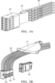
- the harness connector 102 also includes a terminal module 202, a wire dress cover 110 configured to arrange the electrical cables of the wiring harness, and a seal 204 between the wire dress cover 110 and the female outer housing 106 to inhibit entry of environmental contaminants, such as dirt, dust, water, and other fluids into the female outer housing 106.
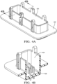
- the header connector 104 includes a shroud 402 having side walls 404 that surround the mating electrical terminals 406.
- the side walls 404 are received within the harness connector 102.
- the mating assist lever 108 is configured to help overcome the mechanical resistance of mating the plurality of electrical terminals 306 in the harness connector 102 to the plurality of mating electrical terminals 406 in the header connector 104.
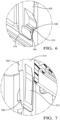
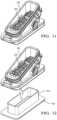
- the female outer housing 106 defines a number of cantilevered flexible locking arms 502 that hold the terminal module 202 within the female outer housing 106.
- stop faces 504 on inner surfaces 506 of each flexible locking arm 502 is separated into a primary surface 508 and a secondary surface 510.
- the flexible locking arms 502 also each have an outer wedge shaped ramp feature 512 on their outer surface 514.
- the secondary surfaces 510 are located at the ends of the locking arms 502, i.e., the secondary surfaces 510 are arranged closer to the free ends 516 of the locking arms 502 than the primary surfaces 508.
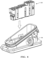
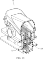
- the terminal module 202 is axially inserted into the female outer housing 106.
- the inner module frame 302 contacts an inner ramp feature 902 on their outer surface 514 on the inner surfaces 506 of the flexible locking arms 502 and pushes the flexible locking arms 502 outwardly until a latch surface 904 on the inner module frame clear the stop faces 504.
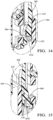
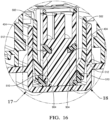
- the primary surface 508 of the stop face 504 of each flexible locking arm 502 contacts an edge 1010 of the latch surface 904 on the inner module frame 302 and the primary surfaces 508 and apply a first force F1 to the inner module frame 302 that holds the terminal module 202 within the female outer housing as shown in FIG. 11 .
- the primary surfaces 510 are arranged substantially parallel to the latch surfaces 904. and the secondary surfaces are nonparallel to both the first surfaces and the latch surfaces.
- the side walls 404 of the shroud 402 contact the outer wedge shaped ramp feature 512 and push the flexible locking arms 502 inwardly so that the angled secondary surface 510 of the stop face 504 of each flexible locking arm 502, rather than the primary surface 508, contacts the latch surface 904 on the inner module frame 302.
- the secondary surfaces 510 are nonparallel to both the primary surfaces 508 and the latch surfaces 904.
- the angled secondary surface 510 acts as a wedge and applies a second force F2 that pushes the inner module frame 302 toward the header connector 104, thereby increasing the terminal overlap of the terminals 306 and the mating terminals 406 and reducing the likelihood of relative movement between the terminals 306 and the mating terminals 406 caused by vibration that may degrade the electrical performance of the connector 100.
- the second force F2 is greater than the first force F1.
- the first force F1 may have zero magnitude.
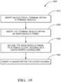
- FIG. 19 is a flowchart of an example method 1900 for assembling an electrical connector 100, comprising the steps of:
- connector assembly While the example presented herein is directed to an electrical connector assembly, alternative embodiments of the connector assembly may be envisioned that are configured to interconnect fiber optic cables, pneumatic tubes, hydraulic tubes, or a hybrid connector assembly having a combination of any of these types of conductors.
- 'one or more' includes a function being performed by one element, a function being performed by more than one element, e.g., in a distributed fashion, several functions being performed by one element, several functions being performed by several elements, or any combination of the above.
- the term “if' is, optionally, construed to mean “when” or “upon” or “in response to determining” or “in response to detecting,” depending on the context.
- the phrase “if it is determined” or “if [a stated condition or event] is detected” is, optionally, construed to mean “upon determining” or “in response to determining” or “upon detecting [the stated condition or event]” or “in response to detecting [the stated condition or event],” depending on the context.
Landscapes
- Connector Housings Or Holding Contact Members (AREA)
- Details Of Connecting Devices For Male And Female Coupling (AREA)
Applications Claiming Priority (1)
| Application Number | Priority Date | Filing Date | Title |
|---|---|---|---|
| US18/092,989 US12308568B2 (en) | 2023-01-04 | 2023-01-04 | Connector assembly with flexible lock and event driven wedge |
Publications (2)
| Publication Number | Publication Date |
|---|---|
| EP4398426A1 true EP4398426A1 (fr) | 2024-07-10 |
| EP4398426B1 EP4398426B1 (fr) | 2025-06-25 |
Family
ID=89119179
Family Applications (1)
| Application Number | Title | Priority Date | Filing Date |
|---|---|---|---|
| EP23214382.6A Active EP4398426B1 (fr) | 2023-01-04 | 2023-12-05 | Ensemble connecteur avec verrou flexible et cale entraînée par événement |
Country Status (3)
| Country | Link |
|---|---|
| US (1) | US12308568B2 (fr) |
| EP (1) | EP4398426B1 (fr) |
| CN (1) | CN118299846A (fr) |
Citations (2)
| Publication number | Priority date | Publication date | Assignee | Title |
|---|---|---|---|---|
| US9847601B2 (en) * | 2015-08-31 | 2017-12-19 | Delphi International Operations Luxenbourg S.A.R.L. | Electrical connector |
| DE112014003938B4 (de) * | 2013-08-30 | 2018-02-08 | Yazaki Corporation | Verbinder |
Family Cites Families (12)
| Publication number | Priority date | Publication date | Assignee | Title |
|---|---|---|---|---|
| US6171146B1 (en) * | 1998-02-19 | 2001-01-09 | Delphi Technologies, Inc. | Repair method for dual lock multi-row electrical connector system |
| US6332789B1 (en) * | 1999-05-31 | 2001-12-25 | Yazaki Corporation | Connector supporting mechanism |
| US6558176B1 (en) * | 2002-03-07 | 2003-05-06 | Tyco Electronics Corp. | Mate assist assembly for connecting electrical contacts |
| US6960090B2 (en) * | 2002-08-07 | 2005-11-01 | Tyco Electronics Amp Gmbh | Plug connector arrangement with latching actuation slide means |
| DE102004013476A1 (de) * | 2003-04-16 | 2004-11-04 | Tyco Electronics Amp Gmbh | Steckverbinderanordnung |
| US7645151B2 (en) * | 2007-03-22 | 2010-01-12 | Tyco Electronics Corporation | Shunted electrical connector and shunt therefore |
| JP4988430B2 (ja) * | 2007-05-18 | 2012-08-01 | 三菱電線工業株式会社 | レバー式コネクタ |
| JP2009259442A (ja) * | 2008-04-14 | 2009-11-05 | Molex Inc | コネクタ |
| DE102009056184B4 (de) * | 2008-12-22 | 2012-10-04 | Sumitomo Wiring Systems, Ltd. | Verbinder |
| JP5961493B2 (ja) * | 2012-09-04 | 2016-08-02 | 矢崎総業株式会社 | コネクタ装置 |
| JP2014165027A (ja) * | 2013-02-26 | 2014-09-08 | Sumitomo Wiring Syst Ltd | 倍力機構付きコネクタ |
| US9142916B2 (en) * | 2013-03-15 | 2015-09-22 | Tyco Electronics Corporation | Connector assembly with receptacle carriers |
-
2023
- 2023-01-04 US US18/092,989 patent/US12308568B2/en active Active
- 2023-12-05 EP EP23214382.6A patent/EP4398426B1/fr active Active
- 2023-12-15 CN CN202311739673.4A patent/CN118299846A/zh active Pending
Patent Citations (2)
| Publication number | Priority date | Publication date | Assignee | Title |
|---|---|---|---|---|
| DE112014003938B4 (de) * | 2013-08-30 | 2018-02-08 | Yazaki Corporation | Verbinder |
| US9847601B2 (en) * | 2015-08-31 | 2017-12-19 | Delphi International Operations Luxenbourg S.A.R.L. | Electrical connector |
Also Published As
| Publication number | Publication date |
|---|---|
| US20240222907A1 (en) | 2024-07-04 |
| EP4398426B1 (fr) | 2025-06-25 |
| US12308568B2 (en) | 2025-05-20 |
| CN118299846A (zh) | 2024-07-05 |
Similar Documents
| Publication | Publication Date | Title |
|---|---|---|
| US10374328B2 (en) | Terminal fitting with hood | |
| US6840789B2 (en) | Connector and a method of assembling it | |
| EP0384577A2 (fr) | Connecteur électrique pour injecteur de combustible et ses bornes | |
| EP3155695B1 (fr) | Soulagement de traction de câble | |
| US11515660B2 (en) | Electrical connector assembly with retaining device | |
| KR20140139577A (ko) | 커넥터를 조립하기 위한 구조 및 방법 | |
| CN110313110B (zh) | 电端子以及连接器组件 | |
| CN110401073B (zh) | 用于电连接器组件的电屏蔽构件 | |
| CN109256642B (zh) | 连接器后壳组件 | |
| EP4297193A1 (fr) | Ensemble connecteur électrique à éléments de verrouillage de borne flexibles et rigides | |
| EP4398426A1 (fr) | Ensemble connecteur avec verrou flexible et cale entraînée par événement | |
| US7011539B1 (en) | Seal for an electrical connector | |
| CN110383595A (zh) | 连接器 | |
| US11450985B2 (en) | Connector with integrated seal retainer and secondary terminal lock | |
| WO2013153089A1 (fr) | Dispositif de contact électrique, en particulier dispositif de contact de prise électrique | |
| US12562520B2 (en) | Connector assembly with terminal position assurance and blocking feature | |
| US7044766B2 (en) | Automotive electrical connection box and method of assembling thereof | |
| EP4542779A1 (fr) | Ensemble connecteur avec dispositif d'adaptation d'une borne à un corps de connecteur et son procédé d'assemblage | |
| EP4734293A1 (fr) | Couvercle de protection de fil pour connecteur électrique | |
| US12266885B2 (en) | Seal retainer with seal expansion compensation features | |
| US20250309578A1 (en) | Interlocking connector design for electrical connectors | |
| US20240022017A1 (en) | Electrical connector for connecting high voltage power cable including electrical conductor to electrical terminal | |
| US20250316928A1 (en) | Connector having retention feature for lever and slide mating assist mechanism | |
| CN117276944A (zh) | 具有挠性和刚性端子锁定特征的电连接器组件 | |
| CN117438813A (zh) | 具有端子位置保证和阻挡特征的连接器组件 |
Legal Events
| Date | Code | Title | Description |
|---|---|---|---|
| PUAI | Public reference made under article 153(3) epc to a published international application that has entered the european phase |
Free format text: ORIGINAL CODE: 0009012 |
|
| STAA | Information on the status of an ep patent application or granted ep patent |
Free format text: STATUS: THE APPLICATION HAS BEEN PUBLISHED |
|
| AK | Designated contracting states |
Kind code of ref document: A1 Designated state(s): AL AT BE BG CH CY CZ DE DK EE ES FI FR GB GR HR HU IE IS IT LI LT LU LV MC ME MK MT NL NO PL PT RO RS SE SI SK SM TR |
|
| STAA | Information on the status of an ep patent application or granted ep patent |
Free format text: STATUS: REQUEST FOR EXAMINATION WAS MADE |
|
| RAP3 | Party data changed (applicant data changed or rights of an application transferred) |
Owner name: APTIV TECHNOLOGIES AG |
|
| 17P | Request for examination filed |
Effective date: 20240828 |
|
| RBV | Designated contracting states (corrected) |
Designated state(s): AL AT BE BG CH CY CZ DE DK EE ES FI FR GB GR HR HU IE IS IT LI LT LU LV MC ME MK MT NL NO PL PT RO RS SE SI SK SM TR |
|
| GRAP | Despatch of communication of intention to grant a patent |
Free format text: ORIGINAL CODE: EPIDOSNIGR1 |
|
| STAA | Information on the status of an ep patent application or granted ep patent |
Free format text: STATUS: GRANT OF PATENT IS INTENDED |
|
| RIC1 | Information provided on ipc code assigned before grant |
Ipc: H01R 13/518 20060101ALN20250113BHEP Ipc: H01R 13/514 20060101ALI20250113BHEP Ipc: H01R 13/506 20060101AFI20250113BHEP |
|
| INTG | Intention to grant announced |
Effective date: 20250127 |
|
| GRAS | Grant fee paid |
Free format text: ORIGINAL CODE: EPIDOSNIGR3 |
|
| GRAA | (expected) grant |
Free format text: ORIGINAL CODE: 0009210 |
|
| STAA | Information on the status of an ep patent application or granted ep patent |
Free format text: STATUS: THE PATENT HAS BEEN GRANTED |
|
| AK | Designated contracting states |
Kind code of ref document: B1 Designated state(s): AL AT BE BG CH CY CZ DE DK EE ES FI FR GB GR HR HU IE IS IT LI LT LU LV MC ME MK MT NL NO PL PT RO RS SE SI SK SM TR |
|
| REG | Reference to a national code |
Ref country code: GB Ref legal event code: FG4D |
|
| REG | Reference to a national code |
Ref country code: CH Ref legal event code: EP |
|
| P01 | Opt-out of the competence of the unified patent court (upc) registered |
Free format text: CASE NUMBER: APP_25283/2025 Effective date: 20250527 |
|
| REG | Reference to a national code |
Ref country code: DE Ref legal event code: R096 Ref document number: 602023004309 Country of ref document: DE |
|
| REG | Reference to a national code |
Ref country code: CH Ref legal event code: EP |
|
| REG | Reference to a national code |
Ref country code: IE Ref legal event code: FG4D |
|
| PG25 | Lapsed in a contracting state [announced via postgrant information from national office to epo] |
Ref country code: FI Free format text: LAPSE BECAUSE OF FAILURE TO SUBMIT A TRANSLATION OF THE DESCRIPTION OR TO PAY THE FEE WITHIN THE PRESCRIBED TIME-LIMIT Effective date: 20250625 |
|
| REG | Reference to a national code |
Ref country code: LT Ref legal event code: MG9D |
|
| PG25 | Lapsed in a contracting state [announced via postgrant information from national office to epo] |
Ref country code: NO Free format text: LAPSE BECAUSE OF FAILURE TO SUBMIT A TRANSLATION OF THE DESCRIPTION OR TO PAY THE FEE WITHIN THE PRESCRIBED TIME-LIMIT Effective date: 20250925 Ref country code: GR Free format text: LAPSE BECAUSE OF FAILURE TO SUBMIT A TRANSLATION OF THE DESCRIPTION OR TO PAY THE FEE WITHIN THE PRESCRIBED TIME-LIMIT Effective date: 20250926 |
|
| PG25 | Lapsed in a contracting state [announced via postgrant information from national office to epo] |
Ref country code: BG Free format text: LAPSE BECAUSE OF FAILURE TO SUBMIT A TRANSLATION OF THE DESCRIPTION OR TO PAY THE FEE WITHIN THE PRESCRIBED TIME-LIMIT Effective date: 20250625 |
|
| PG25 | Lapsed in a contracting state [announced via postgrant information from national office to epo] |
Ref country code: HR Free format text: LAPSE BECAUSE OF FAILURE TO SUBMIT A TRANSLATION OF THE DESCRIPTION OR TO PAY THE FEE WITHIN THE PRESCRIBED TIME-LIMIT Effective date: 20250625 |
|
| PG25 | Lapsed in a contracting state [announced via postgrant information from national office to epo] |
Ref country code: RS Free format text: LAPSE BECAUSE OF FAILURE TO SUBMIT A TRANSLATION OF THE DESCRIPTION OR TO PAY THE FEE WITHIN THE PRESCRIBED TIME-LIMIT Effective date: 20250925 |
|
| PG25 | Lapsed in a contracting state [announced via postgrant information from national office to epo] |
Ref country code: LV Free format text: LAPSE BECAUSE OF FAILURE TO SUBMIT A TRANSLATION OF THE DESCRIPTION OR TO PAY THE FEE WITHIN THE PRESCRIBED TIME-LIMIT Effective date: 20250625 |
|
| REG | Reference to a national code |
Ref country code: NL Ref legal event code: MP Effective date: 20250625 |
|
| PG25 | Lapsed in a contracting state [announced via postgrant information from national office to epo] |
Ref country code: NL Free format text: LAPSE BECAUSE OF FAILURE TO SUBMIT A TRANSLATION OF THE DESCRIPTION OR TO PAY THE FEE WITHIN THE PRESCRIBED TIME-LIMIT Effective date: 20250625 |
|
| PG25 | Lapsed in a contracting state [announced via postgrant information from national office to epo] |
Ref country code: PT Free format text: LAPSE BECAUSE OF FAILURE TO SUBMIT A TRANSLATION OF THE DESCRIPTION OR TO PAY THE FEE WITHIN THE PRESCRIBED TIME-LIMIT Effective date: 20251027 |
|
| REG | Reference to a national code |
Ref country code: AT Ref legal event code: MK05 Ref document number: 1807586 Country of ref document: AT Kind code of ref document: T Effective date: 20250625 |
|
| PG25 | Lapsed in a contracting state [announced via postgrant information from national office to epo] |
Ref country code: IS Free format text: LAPSE BECAUSE OF FAILURE TO SUBMIT A TRANSLATION OF THE DESCRIPTION OR TO PAY THE FEE WITHIN THE PRESCRIBED TIME-LIMIT Effective date: 20251025 |
|
| PGFP | Annual fee paid to national office [announced via postgrant information from national office to epo] |
Ref country code: DE Payment date: 20251117 Year of fee payment: 3 |
|
| PG25 | Lapsed in a contracting state [announced via postgrant information from national office to epo] |
Ref country code: AT Free format text: LAPSE BECAUSE OF FAILURE TO SUBMIT A TRANSLATION OF THE DESCRIPTION OR TO PAY THE FEE WITHIN THE PRESCRIBED TIME-LIMIT Effective date: 20250625 Ref country code: SM Free format text: LAPSE BECAUSE OF FAILURE TO SUBMIT A TRANSLATION OF THE DESCRIPTION OR TO PAY THE FEE WITHIN THE PRESCRIBED TIME-LIMIT Effective date: 20250625 |
|
| PGFP | Annual fee paid to national office [announced via postgrant information from national office to epo] |
Ref country code: FR Payment date: 20251112 Year of fee payment: 3 |
|
| PG25 | Lapsed in a contracting state [announced via postgrant information from national office to epo] |
Ref country code: CZ Free format text: LAPSE BECAUSE OF FAILURE TO SUBMIT A TRANSLATION OF THE DESCRIPTION OR TO PAY THE FEE WITHIN THE PRESCRIBED TIME-LIMIT Effective date: 20250625 |
|
| PG25 | Lapsed in a contracting state [announced via postgrant information from national office to epo] |
Ref country code: PL Free format text: LAPSE BECAUSE OF FAILURE TO SUBMIT A TRANSLATION OF THE DESCRIPTION OR TO PAY THE FEE WITHIN THE PRESCRIBED TIME-LIMIT Effective date: 20250625 |
|
| PG25 | Lapsed in a contracting state [announced via postgrant information from national office to epo] |
Ref country code: EE Free format text: LAPSE BECAUSE OF FAILURE TO SUBMIT A TRANSLATION OF THE DESCRIPTION OR TO PAY THE FEE WITHIN THE PRESCRIBED TIME-LIMIT Effective date: 20250625 |
|
| PG25 | Lapsed in a contracting state [announced via postgrant information from national office to epo] |
Ref country code: SK Free format text: LAPSE BECAUSE OF FAILURE TO SUBMIT A TRANSLATION OF THE DESCRIPTION OR TO PAY THE FEE WITHIN THE PRESCRIBED TIME-LIMIT Effective date: 20250625 |
|
| PG25 | Lapsed in a contracting state [announced via postgrant information from national office to epo] |
Ref country code: ES Free format text: LAPSE BECAUSE OF FAILURE TO SUBMIT A TRANSLATION OF THE DESCRIPTION OR TO PAY THE FEE WITHIN THE PRESCRIBED TIME-LIMIT Effective date: 20250625 |
|
| PG25 | Lapsed in a contracting state [announced via postgrant information from national office to epo] |
Ref country code: RO Free format text: LAPSE BECAUSE OF FAILURE TO SUBMIT A TRANSLATION OF THE DESCRIPTION OR TO PAY THE FEE WITHIN THE PRESCRIBED TIME-LIMIT Effective date: 20250625 |
|
| PG25 | Lapsed in a contracting state [announced via postgrant information from national office to epo] |
Ref country code: DK Free format text: LAPSE BECAUSE OF FAILURE TO SUBMIT A TRANSLATION OF THE DESCRIPTION OR TO PAY THE FEE WITHIN THE PRESCRIBED TIME-LIMIT Effective date: 20250625 |
|
| PG25 | Lapsed in a contracting state [announced via postgrant information from national office to epo] |
Ref country code: IT Free format text: LAPSE BECAUSE OF FAILURE TO SUBMIT A TRANSLATION OF THE DESCRIPTION OR TO PAY THE FEE WITHIN THE PRESCRIBED TIME-LIMIT Effective date: 20250625 |
|
| PLBE | No opposition filed within time limit |
Free format text: ORIGINAL CODE: 0009261 |
|
| STAA | Information on the status of an ep patent application or granted ep patent |
Free format text: STATUS: NO OPPOSITION FILED WITHIN TIME LIMIT |