EP4398427A1 - Integrierter anschlusskontakt und ladeeinfassung - Google Patents
Integrierter anschlusskontakt und ladeeinfassung Download PDFInfo
- Publication number
- EP4398427A1 EP4398427A1 EP23212678.9A EP23212678A EP4398427A1 EP 4398427 A1 EP4398427 A1 EP 4398427A1 EP 23212678 A EP23212678 A EP 23212678A EP 4398427 A1 EP4398427 A1 EP 4398427A1
- Authority
- EP
- European Patent Office
- Prior art keywords
- charging
- bezel
- connector
- contact
- body member
- Prior art date
- Legal status (The legal status is an assumption and is not a legal conclusion. Google has not performed a legal analysis and makes no representation as to the accuracy of the status listed.)
- Withdrawn
Links
Images



Classifications
-
- H—ELECTRICITY
- H01—ELECTRIC ELEMENTS
- H01R—ELECTRICALLY-CONDUCTIVE CONNECTIONS; STRUCTURAL ASSOCIATIONS OF A PLURALITY OF MUTUALLY-INSULATED ELECTRICAL CONNECTING ELEMENTS; COUPLING DEVICES; CURRENT COLLECTORS
- H01R24/00—Two-part coupling devices, or either of their cooperating parts, characterised by their overall structure
- H01R24/60—Contacts spaced along planar side wall transverse to longitudinal axis of engagement
-
- H—ELECTRICITY
- H01—ELECTRIC ELEMENTS
- H01R—ELECTRICALLY-CONDUCTIVE CONNECTIONS; STRUCTURAL ASSOCIATIONS OF A PLURALITY OF MUTUALLY-INSULATED ELECTRICAL CONNECTING ELEMENTS; COUPLING DEVICES; CURRENT COLLECTORS
- H01R13/00—Details of coupling devices of the kinds covered by groups H01R12/70 or H01R24/00 - H01R33/00
- H01R13/46—Bases; Cases
- H01R13/52—Dustproof, splashproof, drip-proof, waterproof, or flameproof cases
- H01R13/5202—Sealing means between parts of housing or between housing part and a wall, e.g. sealing rings
-
- A—HUMAN NECESSITIES
- A45—HAND OR TRAVELLING ARTICLES
- A45C—PURSES; LUGGAGE; HAND CARRIED BAGS
- A45C11/00—Receptacles for purposes not provided for in groups A45C1/00-A45C9/00
-
- A—HUMAN NECESSITIES
- A45—HAND OR TRAVELLING ARTICLES
- A45C—PURSES; LUGGAGE; HAND CARRIED BAGS
- A45C11/00—Receptacles for purposes not provided for in groups A45C1/00-A45C9/00
- A45C11/24—Etuis for purposes not covered by a single one of groups A45C11/02 - A45C11/22, A45C11/26, A45C11/32 - A45C11/38
-
- H—ELECTRICITY
- H01—ELECTRIC ELEMENTS
- H01R—ELECTRICALLY-CONDUCTIVE CONNECTIONS; STRUCTURAL ASSOCIATIONS OF A PLURALITY OF MUTUALLY-INSULATED ELECTRICAL CONNECTING ELEMENTS; COUPLING DEVICES; CURRENT COLLECTORS
- H01R13/00—Details of coupling devices of the kinds covered by groups H01R12/70 or H01R24/00 - H01R33/00
- H01R13/02—Contact members
-
- H—ELECTRICITY
- H01—ELECTRIC ELEMENTS
- H01R—ELECTRICALLY-CONDUCTIVE CONNECTIONS; STRUCTURAL ASSOCIATIONS OF A PLURALITY OF MUTUALLY-INSULATED ELECTRICAL CONNECTING ELEMENTS; COUPLING DEVICES; CURRENT COLLECTORS
- H01R13/00—Details of coupling devices of the kinds covered by groups H01R12/70 or H01R24/00 - H01R33/00
- H01R13/40—Securing contact members in or to a base or case; Insulating of contact members
-
- H—ELECTRICITY
- H01—ELECTRIC ELEMENTS
- H01R—ELECTRICALLY-CONDUCTIVE CONNECTIONS; STRUCTURAL ASSOCIATIONS OF A PLURALITY OF MUTUALLY-INSULATED ELECTRICAL CONNECTING ELEMENTS; COUPLING DEVICES; CURRENT COLLECTORS
- H01R13/00—Details of coupling devices of the kinds covered by groups H01R12/70 or H01R24/00 - H01R33/00
- H01R13/46—Bases; Cases
- H01R13/52—Dustproof, splashproof, drip-proof, waterproof, or flameproof cases
- H01R13/521—Sealing between contact members and housing, e.g. sealing insert
-
- H—ELECTRICITY
- H01—ELECTRIC ELEMENTS
- H01R—ELECTRICALLY-CONDUCTIVE CONNECTIONS; STRUCTURAL ASSOCIATIONS OF A PLURALITY OF MUTUALLY-INSULATED ELECTRICAL CONNECTING ELEMENTS; COUPLING DEVICES; CURRENT COLLECTORS
- H01R13/00—Details of coupling devices of the kinds covered by groups H01R12/70 or H01R24/00 - H01R33/00
- H01R13/73—Means for mounting coupling parts to apparatus or structures, e.g. to a wall
- H01R13/74—Means for mounting coupling parts in openings of a panel
-
- H—ELECTRICITY
- H02—GENERATION; CONVERSION OR DISTRIBUTION OF ELECTRIC POWER
- H02J—ELECTRIC POWER NETWORKS; CIRCUIT ARRANGEMENTS OR SYSTEMS FOR SUPPLYING OR DISTRIBUTING ELECTRIC POWER; SYSTEMS FOR STORING ELECTRIC ENERGY
- H02J7/00—Circuit arrangements for charging or discharging batteries or for supplying loads from batteries
- H02J7/70—Circuit arrangements for charging or discharging batteries or for supplying loads from batteries characterised by the mechanical construction
- H02J7/751—Circuit arrangements for charging or discharging batteries or for supplying loads from batteries characterised by the mechanical construction concerning the insertion or the connection of the batteries
-
- H—ELECTRICITY
- H01—ELECTRIC ELEMENTS
- H01R—ELECTRICALLY-CONDUCTIVE CONNECTIONS; STRUCTURAL ASSOCIATIONS OF A PLURALITY OF MUTUALLY-INSULATED ELECTRICAL CONNECTING ELEMENTS; COUPLING DEVICES; CURRENT COLLECTORS
- H01R2201/00—Connectors or connections adapted for particular applications
- H01R2201/06—Connectors or connections adapted for particular applications for computer periphery
-
- H—ELECTRICITY
- H01—ELECTRIC ELEMENTS
- H01R—ELECTRICALLY-CONDUCTIVE CONNECTIONS; STRUCTURAL ASSOCIATIONS OF A PLURALITY OF MUTUALLY-INSULATED ELECTRICAL CONNECTING ELEMENTS; COUPLING DEVICES; CURRENT COLLECTORS
- H01R2201/00—Connectors or connections adapted for particular applications
- H01R2201/16—Connectors or connections adapted for particular applications for telephony
Definitions
- the present disclosure is directed to a connector assembly including a connector (e.g., USB-C) with an integrated contact charging bezel.
- a connector e.g., USB-C
- an integrated contact charging bezel e.g., USB-C
- Consumer electronics devices commonly include a communications port, such as a micro-USB, USB-C, lighting, thunderbolt, etc., port, in addition to wireless charging components or a contact charging connector for charging the device while the device is in a dock or on charging pad.
- a communications port such as a micro-USB, USB-C, lighting, thunderbolt, etc.
- the contacts of the contact charging connector are located separately from the communications port and are typically insert molded to a housing of the device or assembled into holes in the housing.
- Providing separate wireless charging contact components or a separate contact charging port in an electronic device adds manufacturing expense and design/manufacturing complexity.
- providing a separate contact charging port in an electronic device adds other potential ingress points through which environmental contaminants such as debris and liquids can enter and potentially damage the electronic device.
- the USB-C connector can further include conductive members disposed on the body member.
- the arm structure can be configured to contact the conductive members to be electrically connected to the conductive members.
- the conductive members can be spring clips configured to apply respective forces to the arm structure.
- the arm structure can include recessed portions configured to receive the spring clips to retain the USB-C connector in place.
- the connector assembly can further include a bezel housing covering exterior surfaces of a section of the arm structure and interior surfaces of the section of the arm structure.
- a connector assembly for providing data transfer and charging connections, the connector assembly comprising: a connector, a first bezel member, and a second bezel member.
- the connector can include: a body member; and a connector tongue mounted in the body member and configured to connect to a plug for either one or both of data transfer and power delivery.
- the first bezel member can be configured to be mounted on the connector and can include a first charging contact configured to be placed in contact with a contact element of a charging device.
- the second bezel member can be configured to be mounted on the connector and can include a second charging contact configured to be placed in contact with another contact element of the charging device.
- the connector tongue can be configured to be disposed between the first and second bezel members.
- an electronic device can include: an outer case having an opening; a connector; and a contact charging bezel.
- the connector can be electrically connected to a printed circuit board (FPC) and can include: a body member mounted on the FPC; and a connector tongue mounted in the body member and aligned with the opening, the connector tongue being configured to connect to a plug for either one or both of data transfer and power delivery.
- the contact charging bezel can include: charging contacts exposed at the opening and configured to be placed in contact with conductive contact elements of a charging device, and an arm structure connected to the charging contacts and configured to be mounted on the connector.
- the electronic device can further include a bezel housing covering a section of the arm structure.
- the contact charging bezel can be retained by a mounting bracket in the outer case such that the bezel housing interfaces with the mounting bracket.
- the charging contacts can be exposed from an end of the bezel housing.
- the electronic device can further include a gasket disposed on the charging contacts between the opening and the end of the bezel housing.
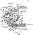
- first charging contact 162 and the first arm 166 can be integrally formed, and the second charging contact 172 and the second arm 176 can be integrally formed.
- first charging contact 162 and the first arm 166 can be separate components that are bonded or fastened together, and the second charging contact 172 and the second arm 176 can be separate components that and bonded or fastened together.
- the interior portion 182 of the bezel housing 180 can be disposed between opposing side portions of the first and second charging contacts 162 and 172.
- the interior portion 182 of the bezel housing 180 spaces apart the first and second charging contacts 162 and 172 to prevent the first and second charging contacts 162 and 172 from contacting each other.
- the interior portion 182 of the bezel housing 180 electrically insulates the first and second bezel members 160 and 170 from each other by electrically insulating the first and second charging contacts 162 and 172 from each other.
- the bezel housing 180 can have a stepped external surface 180a corresponding to the stepped external surfaces of the front portion 166a of the first arm 166 and the front portion 176a of the second arm 176.
- a second gasket 104 can be disposed around the body member 120 of the (USB-C) connector.
- the second gasket 104 can be tightly secured around a front end portion of the body member 120 to form a second seal of the connector assembly 100.
- the first end portions 144a of the spring clips 144 can be retained in grooves 167 and 177 in the rear portion 166b of the first arm 166 and the rear portion 176b of the second arm 176, respectively.
- the spring clips 144 can be configured to apply forces against the first and second arms 166 and 176.
- each of the spring clips 144 can apply a force of approximately 1 newton to the first and second arms 166 and 176, respectively.
- the spring clips 144 also function to retain the connector 110 in place in the arm structure 156 of the contact charging bezel 150.
- the spring clips 144 apply sufficient force to prevent separation of the connector 110 from the contact charging bezel 150 and loss of electrical connection between the contact charging bezel 150 and the flexible FPC 200.
- the second gasket 104 can be retained in a recessed portion or groove 184 in the portion of the bezel housing 180 covering the interior surfaces of the front portion 166a of the first arm 166 and the front portion 176a of the second arm 176.
- the second gasket 104 further secures the connector 110 in place in the contact charging bezel 150 and forms a seal preventing contaminants such as liquid, dirt, and debris from propagating past the connector 110 through the space inside the contact charging bezel 150.
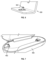
- the connector assembly 100 includes (USB-C or other connector) data and/or charging functionality and contact charging functionality through a single port. That is, a connection with the connector tongue 130 of the connector 110 and a connection with the first and second charging contacts 162 are accessible at the single port opening 14 in the outer case 12 of the electronic device 10.
- USB-C USB-C or other connector
- a USB-C connector assembly includes a USB-C connector and an contact charging bezel integrated with the USB-C connector.
- the contact charging bezel includes charging contacts for contacting conductive contact elements of a charging device and arms extending from the charging contacts and mounted on the USB-C connector.
- the charging contacts can be positioned in a port opening in an outer case of an electronic device.
- the USB-C connector includes a body member, and a connector tongue mounted in the body member and configured to be aligned with the port opening for connecting to a USB-C plug for either one or both of USB-C data transfer and USB-C power delivery.
- the contact charging bezel can accommodate the USB-C connector a space between the arms of the contact charging bezel and the connector tongue can be disposed in a space between the charging contacts.
- the connector assembly providing data transfer/power delivery connectivity and contact charging connectivity through the single port opening in an outer case of an electronic device
- the number of ingress points into the electronic device is reduced in comparison with electronic devices that include multiple openings in an outer case for data and contact charging connectivity.
- the reduced number of ingress points provided by the connector assembly disclosed herein improves waterproofing of the electronic device.
- the connector assembly disclosed herein enables data and contact charging connections to be made at the same location on the electronic device, the data and contact charging connections are intuitive for a user.
- the contact charging bezel at the single port opening, the aesthetic appearance of the electronic device is improved over electronic devices that include multiple openings in an outer case for data and contact charging connectivity.
- the bezel assembly forms a tight seal with the outer case of the electronic device and acts as part of the outer case, thereby further improving waterproofing of the electronic device.
- an electronic device including a connector assembly according to the embodiments disclosed herein can achieve IP 68 and IPx8 waterproof ratings and does not require the charging contacts or other portions of the contact charging bezel to be insert molded with the outer case to form a seal with the outer case.
- the charging bezel can be configured to contact resilient connection members on the body member of the connector to be electrically connected to the resilient connection members, and the resilient contact members are electrically connected to an FPC that is electrically connected to the connector.
- the disclosed embodiments require minimal additional hardware and electrical connections to implement contact charging connectivity together with data/power delivery connectivity, which is an important advantage in miniaturized electronics.
- the embodiments disclosed herein simplify repairs to the electronic device.
- the word “or” refers to any possible permutation of a set of items.
- the phrase “A, B, or C” refers to at least one of A, B, C, or any combination thereof, such as any of: A; B; C; A and B; A and C; B and C; A, B, and C; or multiple of any item such as A and A; B, B, and C; A, A, B, C, and C; etc.
- first,” “second,” and “third” may be used herein to describe various members, components, regions, layers, or sections, these members, components, regions, layers, or sections are not to be limited by these terms. Rather, these terms are only used to distinguish one member, component, region, layer, or section from another member, component, region, layer, or section. Thus, a first member, component, region, layer, or section referred to in examples described herein may also be referred to as a second member, component, region, layer, or section without departing from the teachings of the examples.
Landscapes
- Engineering & Computer Science (AREA)
- Power Engineering (AREA)
- Charge And Discharge Circuits For Batteries Or The Like (AREA)
- Connector Housings Or Holding Contact Members (AREA)
Applications Claiming Priority (1)
| Application Number | Priority Date | Filing Date | Title |
|---|---|---|---|
| US202318149880A | 2023-01-04 | 2023-01-04 |
Publications (1)
| Publication Number | Publication Date |
|---|---|
| EP4398427A1 true EP4398427A1 (de) | 2024-07-10 |
Family
ID=88978261
Family Applications (1)
| Application Number | Title | Priority Date | Filing Date |
|---|---|---|---|
| EP23212678.9A Withdrawn EP4398427A1 (de) | 2023-01-04 | 2023-11-28 | Integrierter anschlusskontakt und ladeeinfassung |
Country Status (2)
| Country | Link |
|---|---|
| EP (1) | EP4398427A1 (de) |
| CN (1) | CN118299849A (de) |
Citations (1)
| Publication number | Priority date | Publication date | Assignee | Title |
|---|---|---|---|---|
| US20170093453A1 (en) * | 2015-09-30 | 2017-03-30 | Apple Inc. | Case with magnetic over-center mechanism |
-
2023
- 2023-11-28 EP EP23212678.9A patent/EP4398427A1/de not_active Withdrawn
-
2024
- 2024-01-03 CN CN202410010648.0A patent/CN118299849A/zh active Pending
Patent Citations (1)
| Publication number | Priority date | Publication date | Assignee | Title |
|---|---|---|---|---|
| US20170093453A1 (en) * | 2015-09-30 | 2017-03-30 | Apple Inc. | Case with magnetic over-center mechanism |
Also Published As
| Publication number | Publication date |
|---|---|
| CN118299849A (zh) | 2024-07-05 |
Similar Documents
| Publication | Publication Date | Title |
|---|---|---|
| US10579097B2 (en) | Electronic device with contacts flush with housing | |
| JP5736137B2 (ja) | フラットケーブル用コネクタ | |
| TWI631774B (zh) | 鍵盤、接觸點結構及組裝接觸點結構之方法 | |
| US6843679B2 (en) | Cable connector assembly | |
| US7527525B2 (en) | Jack connector | |
| US6636725B1 (en) | Antenna equipment and communication terminal equipment | |
| US6095825A (en) | Power adapter for interconnecting different types of power connectors | |
| TW201813221A (zh) | 電連接器 | |
| US6005527A (en) | RF coupler for concealed mobile telecommunications systems utilizing window-mounted antennas and systems using same | |
| US6132224A (en) | Connector assembly for printed circuit | |
| US6435892B1 (en) | Electrical connector with a supporting mechanism | |
| US6994591B2 (en) | Electrical connector for use with flexible printed circuit | |
| EP4398427A1 (de) | Integrierter anschlusskontakt und ladeeinfassung | |
| US20230111985A1 (en) | Low profile auto-dimming interior rearview mirror assembly | |
| US20090181578A1 (en) | Connector assembly | |
| US5921797A (en) | Electrical connector for use with removable electronic console | |
| US6981891B1 (en) | Flexible flat cable connector | |
| US7527529B2 (en) | Microphone connector | |
| CN215989386U (zh) | 电连接器 | |
| US20190252829A1 (en) | Connector | |
| CN215955140U (zh) | 按键结构及电子设备 | |
| JP4482476B2 (ja) | コネクタ及び開口窓部材 | |
| JP2004014353A (ja) | ダイバーシティ受信機用コネクタユニット | |
| JPH10302882A (ja) | 接続構造 | |
| KR102397522B1 (ko) | 커넥터 어셈블리 |
Legal Events
| Date | Code | Title | Description |
|---|---|---|---|
| PUAI | Public reference made under article 153(3) epc to a published international application that has entered the european phase |
Free format text: ORIGINAL CODE: 0009012 |
|
| STAA | Information on the status of an ep patent application or granted ep patent |
Free format text: STATUS: THE APPLICATION HAS BEEN PUBLISHED |
|
| AK | Designated contracting states |
Kind code of ref document: A1 Designated state(s): AL AT BE BG CH CY CZ DE DK EE ES FI FR GB GR HR HU IE IS IT LI LT LU LV MC ME MK MT NL NO PL PT RO RS SE SI SK SM TR |
|
| STAA | Information on the status of an ep patent application or granted ep patent |
Free format text: STATUS: THE APPLICATION HAS BEEN WITHDRAWN |
|
| 18W | Application withdrawn |
Effective date: 20240902 |