EP4398435A1 - Verfahren zum betrieb eines stromversorgungssystems und stromversorgungssystem - Google Patents
Verfahren zum betrieb eines stromversorgungssystems und stromversorgungssystem Download PDFInfo
- Publication number
- EP4398435A1 EP4398435A1 EP23150321.0A EP23150321A EP4398435A1 EP 4398435 A1 EP4398435 A1 EP 4398435A1 EP 23150321 A EP23150321 A EP 23150321A EP 4398435 A1 EP4398435 A1 EP 4398435A1
- Authority
- EP
- European Patent Office
- Prior art keywords
- rotor
- stator
- bus
- current
- generator
- Prior art date
- Legal status (The legal status is an assumption and is not a legal conclusion. Google has not performed a legal analysis and makes no representation as to the accuracy of the status listed.)
- Granted
Links
Images


Classifications
-
- H—ELECTRICITY
- H02—GENERATION; CONVERSION OR DISTRIBUTION OF ELECTRIC POWER
- H02P—CONTROL OR REGULATION OF ELECTRIC MOTORS, ELECTRIC GENERATORS OR DYNAMO-ELECTRIC CONVERTERS; CONTROLLING TRANSFORMERS, REACTORS OR CHOKE COILS
- H02P9/00—Arrangements for controlling electric generators for the purpose of obtaining a desired output
- H02P9/10—Control effected upon generator excitation circuit to reduce harmful effects of overloads or transients, e.g. sudden application of load, sudden removal of load, sudden change of load
- H02P9/105—Control effected upon generator excitation circuit to reduce harmful effects of overloads or transients, e.g. sudden application of load, sudden removal of load, sudden change of load for increasing the stability
-
- H—ELECTRICITY
- H02—GENERATION; CONVERSION OR DISTRIBUTION OF ELECTRIC POWER
- H02J—ELECTRIC POWER NETWORKS; CIRCUIT ARRANGEMENTS OR SYSTEMS FOR SUPPLYING OR DISTRIBUTING ELECTRIC POWER; SYSTEMS FOR STORING ELECTRIC ENERGY
- H02J3/00—Circuit arrangements for AC mains or AC distribution networks
- H02J3/01—Arrangements for reducing harmonics or ripples
-
- F—MECHANICAL ENGINEERING; LIGHTING; HEATING; WEAPONS; BLASTING
- F03—MACHINES OR ENGINES FOR LIQUIDS; WIND, SPRING, OR WEIGHT MOTORS; PRODUCING MECHANICAL POWER OR A REACTIVE PROPULSIVE THRUST, NOT OTHERWISE PROVIDED FOR
- F03D—WIND MOTORS
- F03D9/00—Adaptations of wind motors for special use; Combinations of wind motors with apparatus driven thereby; Wind motors specially adapted for installation in particular locations
- F03D9/20—Wind motors characterised by the driven apparatus
- F03D9/25—Wind motors characterised by the driven apparatus the apparatus being an electrical generator
- F03D9/255—Wind motors characterised by the driven apparatus the apparatus being an electrical generator connected to electrical distribution networks; Arrangements therefor
-
- H—ELECTRICITY
- H02—GENERATION; CONVERSION OR DISTRIBUTION OF ELECTRIC POWER
- H02J—ELECTRIC POWER NETWORKS; CIRCUIT ARRANGEMENTS OR SYSTEMS FOR SUPPLYING OR DISTRIBUTING ELECTRIC POWER; SYSTEMS FOR STORING ELECTRIC ENERGY
- H02J3/00—Circuit arrangements for AC mains or AC distribution networks
- H02J3/38—Arrangements for feeding a single network from two or more generators or sources in parallel; Arrangements for feeding already energised networks from additional generators or sources in parallel
-
- H—ELECTRICITY
- H02—GENERATION; CONVERSION OR DISTRIBUTION OF ELECTRIC POWER
- H02J—ELECTRIC POWER NETWORKS; CIRCUIT ARRANGEMENTS OR SYSTEMS FOR SUPPLYING OR DISTRIBUTING ELECTRIC POWER; SYSTEMS FOR STORING ELECTRIC ENERGY
- H02J3/00—Circuit arrangements for AC mains or AC distribution networks
- H02J3/38—Arrangements for feeding a single network from two or more generators or sources in parallel; Arrangements for feeding already energised networks from additional generators or sources in parallel
- H02J3/381—Dispersed generators
-
- H—ELECTRICITY
- H02—GENERATION; CONVERSION OR DISTRIBUTION OF ELECTRIC POWER
- H02P—CONTROL OR REGULATION OF ELECTRIC MOTORS, ELECTRIC GENERATORS OR DYNAMO-ELECTRIC CONVERTERS; CONTROLLING TRANSFORMERS, REACTORS OR CHOKE COILS
- H02P9/00—Arrangements for controlling electric generators for the purpose of obtaining a desired output
- H02P9/007—Control circuits for doubly fed generators
-
- F—MECHANICAL ENGINEERING; LIGHTING; HEATING; WEAPONS; BLASTING
- F05—INDEXING SCHEMES RELATING TO ENGINES OR PUMPS IN VARIOUS SUBCLASSES OF CLASSES F01-F04
- F05B—INDEXING SCHEME RELATING TO WIND, SPRING, WEIGHT, INERTIA OR LIKE MOTORS, TO MACHINES OR ENGINES FOR LIQUIDS COVERED BY SUBCLASSES F03B, F03D AND F03G
- F05B2220/00—Application
- F05B2220/70—Application in combination with
- F05B2220/706—Application in combination with an electrical generator
-
- H—ELECTRICITY
- H02—GENERATION; CONVERSION OR DISTRIBUTION OF ELECTRIC POWER
- H02J—ELECTRIC POWER NETWORKS; CIRCUIT ARRANGEMENTS OR SYSTEMS FOR SUPPLYING OR DISTRIBUTING ELECTRIC POWER; SYSTEMS FOR STORING ELECTRIC ENERGY
- H02J2101/00—Supply or distribution of decentralised, dispersed or local electric power generation
- H02J2101/20—Dispersed power generation using renewable energy sources
- H02J2101/28—Wind energy
-
- H—ELECTRICITY
- H02—GENERATION; CONVERSION OR DISTRIBUTION OF ELECTRIC POWER
- H02P—CONTROL OR REGULATION OF ELECTRIC MOTORS, ELECTRIC GENERATORS OR DYNAMO-ELECTRIC CONVERTERS; CONTROLLING TRANSFORMERS, REACTORS OR CHOKE COILS
- H02P2101/00—Special adaptation of control arrangements for generators
- H02P2101/15—Special adaptation of control arrangements for generators for wind-driven turbines
Definitions
- the generator rotor may be electrically coupled to a bi-directional power converter that includes a rotor side converter joined to a line side converter via a regulated DC link.
- a bi-directional power converter that includes a rotor side converter joined to a line side converter via a regulated DC link.
- some wind turbines such as wind-driven doubly-fed induction generator (DFIG) systems and full power conversion systems, may include a power converter with an AC-DC-AC topology.
- DFIG doubly-fed induction generator
- the generator stator is often separately connected to the power grid via a main transformer.
- the present disclosure is directed to a method for operating a power supply system connected to a grid, in particular a respective a wind turbine.
- the power supply system includes a rotor, a doubly-fed induction generator (DFIG), a power conversion assembly, and an active filter.
- the DFIG includes a generator rotor mechanically connected with the rotor and a generator stator.
- the power conversion assembly includes a rotor-side power converter.
- the active filter is electrically connected with the generator stator via a stator bus.
- the rotor-side power converter is electrically connected with the generator rotor via a rotor bus.
- the method includes: determining, based on a rotor frequency of the generator rotor, an expected harmonic frequency for a stator current flowing on the stator bus; determining, in a data set comprising stator current values, a current amplitude of the stator current at the expected harmonic frequency; and controlling, based on the current amplitude of the stator current at the expected harmonic frequency, the active filter.
- stator current amplitude of the stator current is also referred to as stator current amplitude (at the given frequency).
- Controlling the active filter typically includes using the expected harmonic frequency and the current amplitude to determine or amend a control signal for actively filtering the stator current at the expected harmonic frequency (frequencies), feeding the control signal to the active filter, and/or using the control signal to control the active filter.
- the number of switches depend on the number of phases of the stator bus.
- an active filter with two switches per phase e.g. six switches for a typical three-phase stator bus may be used.
- three expected harmonic frequencies which typically result from the three major harmonic injections of the rotor-side converter into the rotor bus at two times, three times and four times the switching frequency of the rotor-side power converter, and corresponding current amplitudes may be determined at a given time during exchanging active and or reactive electric power with the grid, in particular feeding (active) electric power to the grid.
- the active filter may be controlled such and/or the control signal be determined such that the stator current at all or a subset of the expected harmonic frequencies is actively filtered.
- stator current is actively filtered by the active filter typically depend on a comparison of the stator current amplitude with a pre-determined corresponding threshold amplitude.
- a respective partial control signal is determined.
- control signal is determined using at least one PLL-control, more particular a respective PLL-control for each partial control signal.
- the control signal can also be determined using proportional resonant control.
- the amplitude(s) of harmonics in stator current are determined using a Discrete Fourier Transform, DFT, or a Fast Fourier Transform (FFT).
- DFT Discrete Fourier Transform
- FFT Fast Fourier Transform
- the active filter may be electrically connectable with the stator bus via a two-windings transformer.
- the active filter may include switches which are typically, controllable by a control signal received from the control system to actively filter the stator current at the expected harmonic frequency / frequencies.
- the power supply system includes a step-up transformer connectable with the grid and the stator bus, in particular a three-winding step-up transformer.
- a line filter connectable with the line-side power converter bus may be provided, in particular a respective passive line filter. Passive line filter are found to be sufficient to damp any harmonics caused by switching the line side converter and may not require internal switching elements.
- the power supply system is a wind turbine.
- control system is typically configured to perform any of the methods as explained herein.
- the present disclosure is directed to a computer program product or a non-transitory computer-readable storage medium comprising instructions which, when executed by one or more processors of a power supply system, in particular a control system of the power supply systems as explained herein, cause the system to carry out any of the methods as explained herein.
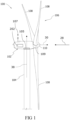
- the rotor blades 108 are spaced about the hub 110 to facilitate rotating the rotor 106 to enable kinetic energy to be transferred from the wind into usable mechanical energy, and subsequently, electrical energy.
- a pitch angle of the rotor blades 108 i.e., an angle that determines a perspective of the rotor blades 108 with respect to the wind direction, may be changed by a pitch system 109 to control the load and power generated by the wind turbine 100 by adjusting an angular position of at least one rotor blade 108 relative to wind vectors.
- the pitch system 109 may change a pitch angle of the rotor blades 108 such that the rotor blades 108 are moved to a feathered position, such that the perspective of at least one rotor blade 108 relative to wind vectors provides a minimal surface area of the rotor blade 108 to be oriented towards the wind vectors, which facilitates reducing a rotational speed and/or facilitates a stall of the rotor 106.
- a blade pitch of each rotor blade 108 may be controlled individually by a (wind turbine) controller 202 or by a pitch control system. Alternatively, the blade pitch for all rotor blades 108 may be controlled simultaneously by said control systems.
- the nacelle 102 may also include at least one meteorological mast 107 that may include a wind vane and anemometer (neither shown in Figure 2 ).
- the mast 107 may provide information to the wind turbine controller 202 regarding ambient conditions. This may include wind direction and/or wind speed as well as ambient temperature, ambient moisture, precipitation type and/or amount (if any).
- the communications module 209 may include a sensor interface 211 (e.g., one or more analog-to-digital converters) to permit signals transmitted from one or more sensors to be converted into signals that can be understood and processed by the processors 204.
- the sensors e.g. sensors 252, 254, 256, 258
- the sensors 252, 254, 256, 258 may be coupled to the sensor interface 211 via a wired connection.
- Step-up transformer circuit breaker 214 is electrically coupled to an electric power step-up transformer 234 via a generator-side bus 236.
- Step-up transformer 234 is electrically coupled to a grid circuit breaker 238 via a breaker-side bus 240.
- Grid circuit breaker 238 is connected to the electric power transmission and distribution grid via a grid bus 242.
- step-up transformer 234 is electrically coupled to one or more fuses (not shown), rather than to grid circuit breaker 238, via breaker-side bus 240.
- neither fuses nor grid circuit breaker 238 is used, but rather step-up transformer 234 is coupled to the electric power transmission and distribution grid via breaker-side bus 240 and grid bus 242.
- the control system of the electrical and control system 200 may include turbine controller 202 and converter controller 262, wherein the turbine controller 202 typically operates as master controller with respect to converter controller 262.
- turbine controller 202 directly controls active filter 270.
- control signal C 270 for the active filter 270 is passed through converter controller 262 or even be determined by converter controller 262.
- a second electrical power transmission path is provided.
- Electrical, three-phase, sinusoidal, AC power is generated within generator rotor 122 and is transmitted to power conversion assembly 210 via rotor bus 212.
- the electrical power is transmitted to rotor filter 218 and the electrical power is modified for the rate of change of the PWM signals associated with rotor-side power converter 220.
- Rotor-side power converter 220 acts as a rectifier and rectifies the sinusoidal, three-phase AC power to DC power.
- the DC power is transmitted into DC link 244.
- Capacitor 250 facilitates mitigating DC link 244 voltage amplitude variations by facilitating mitigation of a DC ripple associated with AC rectification.
- the DC power is subsequently transmitted from DC link 244 to rotor-side power converter 220 and rotor-side power converter 220 acts as an inverter configured to convert the DC electrical power transmitted from DC link 244 to a three-phase, sinusoidal AC electrical power with pre-determined voltages, currents, and frequencies. This conversion is monitored and controlled via converter controller 262.
- the converted AC power is transmitted from rotor-side power converter 220 to rotor filter 218 via rotor filter bus 219 and is subsequently transmitted to generator rotor 122 via rotor bus 212, thereby facilitating sub-synchronous operation.
- the rotor-side power converter 220 is electrically coupled with the generator rotor 122 via a rotor bus 212. Further, the line-side power converter 221 is electrically coupled with a first winding of a three winding (main) step-up transformer 234 via a line bus 223, and the stator 120 is electrically coupled with a second winding of transformer 234 via a stator bus 208. A third winding of step-up transformer 234 is electrically coupled with utility grid 242.
- the busses 208, 212, 223 may be three phase AC busses. Step-up transformer 234 may step up the voltage of stator bus 208 (of e.g. 6 kV) and line bus 223 (of e.g. 690 V) to a desired grid voltage (of e.g. 35 kV).
- the values ⁇ sh and ⁇ ef refer to the phase angle of stator harmonic current and phase angle between rotor and stator in steady-state, respectively.
- the apostrophe ( ⁇ ) indicates that the quantities are referred to the stator frame (see E. Hernández and M. Madrigal, "A Step Forward in the Modeling of the Doubly-fed Induction Machine for Harmonic Analysis", IEEE Transactions on Energy Conversion, vol. 29/1, p. 149-157, DOI: 10.1109/TEC.2013.2290297 ).
- Eq. II may even be used during runtime to determine the stator current harmonics f h .
- stator current amplitudes ⁇ I h ⁇ may be determined in stator current Is as measured by electric current sensors 254, i.e. in a respective dataset ⁇ Is ⁇ listing values of stator current Is, and received by control system 202, 262.
- a primary controller 202 of power supply system 100' typically a respective turbine controller 202 may be used to determine the stator current amplitudes ⁇ I h ⁇ for the stator current harmonics ⁇ f h ⁇ , and to determine, based thereon, a control signal C 270 for the active filter 270 to actively at least damp undesired stator current harmonics.
- active filter 270 is electrically coupled to stator path via a two-winding transformer 275 reducing the output voltages of active filter 270.
- Active filter 270 is coupled in parallel with stator bus 208.
- Control signal C 270 causes switching of switches of active filter 270 to damp, reduce or even substantially cancel harmonics caused by operating rotor-side converter 222 (in an overmodulation regime or close to an overmodulation regime).
- active filter 270 may reduce or cancel harmonics to satisfy one or more grid requirements for harmonics.
- Active filter 270 may in particular provide current at about the same frequency and/or amplitude as the harmonics on stator path 208 and at an opposite phase, i.e. about 180 degrees out of phase.
- Active filter 270 may even provide electric current with a high degree of precision to cancel harmonics, even harmonics close to the fundamental frequency or grid frequency f g , with low, reduced or no impact on the power at the fundamental frequency.
- stator path 208 using an active filter 270 and the proposed adaptive control, respectively, instead of a passive filter coupled to stator path 208 can be shown to be more efficient. This is mainly due to the fact that harmonics at stator path depend on operating conditions, in particular rotor frequency and slip, respectively.
- controller 202 of power supply system 100' may, in a first block 280, determine the expected harmonic frequencies ⁇ f h ⁇ for the stator current Is on stator bus 208 based on the typically measured generator rotor frequency f g , and typically also on the (measured) grid frequency f g and a switching frequency f c (known to controller 202) of the RSC. In many situations, grid frequency f g and/or switching frequency f c may be assumed to be constant.
- current amplitudes ⁇ I h ⁇ for the expected harmonic frequencies ⁇ f h ⁇ may be determined in measured data set with stator current values ⁇ Is ⁇ , in particular as corresponding data pairs ⁇ f h , I h ⁇ .
- data pairs ⁇ f h , I h ⁇ may be used to determine a control signal C 270 for the active filter.
- Blocks 280, 290 and 300 may be implemented in software and/or hardware, for example in software only.
- a pre-determined look-up table is used in block 280 to directly determine the expected harmonic stator frequencies ⁇ f h ⁇ .
- a first block 281 (one or more, for example two or three) expected harmonic frequencies ⁇ f h ⁇ r for the rotor current Ir flowing on the rotor bus may, based on generator rotor frequency fr and optionally on the (measured) grid frequency f g and a switching frequency f c of the RSC, be determined. This may be achieved using a respective predetermined look-up table.
- phase sequences ( ⁇ ⁇ sh , ⁇ ' sh ⁇ for the rotor current Ir may be determined based on the expected harmonic rotor frequencies ⁇ f h ⁇ r .
- a slip f slip of the generator rotor 122 with respect to the generator stator 120 may be calculated.
- the expected harmonic stator frequencies ⁇ f h ⁇ may be calculated using the slip f slip and the phase sequences.
- Block 292 may in particular output a set of harmonic frequencies and amplitudes ⁇ ( f h ,, I h ,) ⁇ used as input for determining the control signal for the active filter.
- block 300 of determining control signal C 270 as explained above with respect to FIG. 4B may include respective (sub-) blocks 300i, 300j, 300k for each harmonics h, h' to be damped (at three exemplary frequencies f, f, f k ).
- Each block 300i, 300j, 300k receives the expected harmonic f i , f j , f k and corresponding current amplitude I i , I j , I k , and determines a respective partial control signal Ci, Cj, Ck.
- the control signal C 270 may then be calculated as a sum of the partial control signals Ci, Cj, Ck, in a block 300s.
- FIG. 6A illustrates a flow chart of a method 1000 for operating a grid-connected power supply system, in particular a respective wind turbine.
- a data set with stator current values is used to determine a current amplitude of the stator current at the expected harmonic frequency.
- the current amplitude of the stator current at the expected harmonic frequency is used for controlling an active filter electrically coupled with the stator bus so that the current amplitude of the stator current at the expected harmonic frequency is reduced and/or a grid requirement for the expected harmonic frequency is complied with.
- blocks 1100 - 1300 may be performed several time and in a cyclic manner, respectively.
- the method explained herein may also be described as determining (in block 1100), based on a (comparatively easily determinable, in particular comparatively easily measurable / measured) rotor frequency of the generator rotor of a DFIG-based power supply system, an expected harmonic frequency of a stator current, i.e. the frequency of a harmonic stator current component, typically several expected harmonic frequencies for a stator current, flowing on a stator bus of the DFIG-based power supply system, and controlling the active filter based on the expected harmonic frequency (frequencies), typically including blocks 1200, 1300.
- FIG. 6B illustrates a flow chart of a method 2000 for operating a grid-connected power supply system, in particular a respective wind turbine.
- Method 2000 may be similar to method 1000 and also includes blocks 2100, 2200 of determining one or more expected harmonic frequencies, and one or more current amplitudes, respectively, but is more specific in block 2300.
- the expected one or more harmonic frequencies and the current amplitudes are used to determine (in a first cycle) or amend (in subsequent cycles) a control signal for the active filter, in a (sub-) block 2320.
- a (sub-) block 3310 it is, for at least one current amplitude I h , checked if the current amplitude I h is equal to or larger than a pre-determined corresponding threshold amplitude I h_th at the respective expected harmonic frequency h, in particular a corresponding threshold amplitude according to a grid code
- the expected harmonic frequency f h and the corresponding current amplitude I h are used to determine or amend the control signal in a (sub-) block 3320, which is used for controlling the active filter in a subsequent (sub-) block 3330.
- controlling of the active filter may not be amended or activated, and the method may return to block 3100.
- the method includes: determining, based on a rotor frequency of the generator rotor, an expected harmonic frequency for a stator current (an expected frequency for a harmonic stator current component) flowing on the stator bus, and using the expected (harmonic) frequency to determine a control signal for the active filter (and/or to control the active filter) to counteract the harmonic stator current component and/or so that (an amplitude of) the stator current (harmonic stator current component) at and/or next to the expected harmonic frequency is at least reduced.
- Embodiments of the present invention have been described above with reference to block diagrams and flowchart illustrations of methods, apparatuses (i.e., systems) and computer program products. It will be understood that each block of the block diagrams and flowchart illustrations, and combinations of blocks in the block diagrams and flowchart illustrations, respectively, can be implemented by various means including computer program instructions. These computer program instructions may be loaded onto a general purpose computer, special purpose computer, or other programmable data processing apparatus, such as the processor(s) 204 discussed above with reference to FIG. 3A , to produce a machine, such that the instructions which execute on the computer or other programmable data processing apparatus create a means for implementing the functions specified in the flowchart block or blocks.
- blocks of the block diagrams and flowchart illustrations support combinations of means for performing the specified functions, combinations of steps for performing the specified functions and program instruction means for performing the specified functions. It will also be understood that each block of the block diagrams and flowchart illustrations, and combinations of blocks in the block diagrams and flowchart illustrations, can be implemented by special purpose hardware-based computer systems that perform the specified functions or steps, or combinations of special purpose hardware and computer instructions.
Landscapes
- Engineering & Computer Science (AREA)
- Power Engineering (AREA)
- Life Sciences & Earth Sciences (AREA)
- Sustainable Development (AREA)
- Sustainable Energy (AREA)
- Chemical & Material Sciences (AREA)
- Combustion & Propulsion (AREA)
- Mechanical Engineering (AREA)
- General Engineering & Computer Science (AREA)
- Control Of Eletrric Generators (AREA)
Priority Applications (5)
| Application Number | Priority Date | Filing Date | Title |
|---|---|---|---|
| ES23150321T ES3062712T3 (en) | 2023-01-04 | 2023-01-04 | A method for operating a power supply system and a power supply system |
| EP23150321.0A EP4398435B1 (de) | 2023-01-04 | 2023-01-04 | Verfahren zum betrieb eines stromversorgungssystems und stromversorgungssystem |
| DK23150321.0T DK4398435T3 (da) | 2023-01-04 | 2023-01-04 | Fremgangsmåde til drift af et effektforsyningssystem og et effekt-forsyningssystem |
| CN202410002839.2A CN118300106A (zh) | 2023-01-04 | 2024-01-02 | 用于操作功率供应系统的方法和功率供应系统 |
| US18/403,017 US12381497B2 (en) | 2023-01-04 | 2024-01-03 | Method for operating a power supply system that supplies power to a grid to maintain stator current occurring at a harmonic frequency below a threshold value |
Applications Claiming Priority (1)
| Application Number | Priority Date | Filing Date | Title |
|---|---|---|---|
| EP23150321.0A EP4398435B1 (de) | 2023-01-04 | 2023-01-04 | Verfahren zum betrieb eines stromversorgungssystems und stromversorgungssystem |
Publications (2)
| Publication Number | Publication Date |
|---|---|
| EP4398435A1 true EP4398435A1 (de) | 2024-07-10 |
| EP4398435B1 EP4398435B1 (de) | 2025-11-19 |
Family
ID=84819906
Family Applications (1)
| Application Number | Title | Priority Date | Filing Date |
|---|---|---|---|
| EP23150321.0A Active EP4398435B1 (de) | 2023-01-04 | 2023-01-04 | Verfahren zum betrieb eines stromversorgungssystems und stromversorgungssystem |
Country Status (5)
| Country | Link |
|---|---|
| US (1) | US12381497B2 (de) |
| EP (1) | EP4398435B1 (de) |
| CN (1) | CN118300106A (de) |
| DK (1) | DK4398435T3 (de) |
| ES (1) | ES3062712T3 (de) |
Families Citing this family (1)
| Publication number | Priority date | Publication date | Assignee | Title |
|---|---|---|---|---|
| EP4398435B1 (de) * | 2023-01-04 | 2025-11-19 | General Electric Renovables España S.L. | Verfahren zum betrieb eines stromversorgungssystems und stromversorgungssystem |
Citations (3)
| Publication number | Priority date | Publication date | Assignee | Title |
|---|---|---|---|---|
| US20110074365A1 (en) * | 2009-09-30 | 2011-03-31 | Hitachi, Ltd. | Wind power generating system and control method for the same |
| EP3484007A1 (de) * | 2017-11-09 | 2019-05-15 | General Electric Company | Dfig-konverter-übermodulation |
| EP3745551A1 (de) * | 2019-05-30 | 2020-12-02 | General Electric Company | System und verfahren zur steuerung der harmonischen oberwellen in einem energiesystem für erneuerbare energien |
Family Cites Families (1)
| Publication number | Priority date | Publication date | Assignee | Title |
|---|---|---|---|---|
| EP4398435B1 (de) * | 2023-01-04 | 2025-11-19 | General Electric Renovables España S.L. | Verfahren zum betrieb eines stromversorgungssystems und stromversorgungssystem |
-
2023
- 2023-01-04 EP EP23150321.0A patent/EP4398435B1/de active Active
- 2023-01-04 DK DK23150321.0T patent/DK4398435T3/da active
- 2023-01-04 ES ES23150321T patent/ES3062712T3/es active Active
-
2024
- 2024-01-02 CN CN202410002839.2A patent/CN118300106A/zh active Pending
- 2024-01-03 US US18/403,017 patent/US12381497B2/en active Active
Patent Citations (3)
| Publication number | Priority date | Publication date | Assignee | Title |
|---|---|---|---|---|
| US20110074365A1 (en) * | 2009-09-30 | 2011-03-31 | Hitachi, Ltd. | Wind power generating system and control method for the same |
| EP3484007A1 (de) * | 2017-11-09 | 2019-05-15 | General Electric Company | Dfig-konverter-übermodulation |
| EP3745551A1 (de) * | 2019-05-30 | 2020-12-02 | General Electric Company | System und verfahren zur steuerung der harmonischen oberwellen in einem energiesystem für erneuerbare energien |
Non-Patent Citations (2)
| Title |
|---|
| M. MADRIGAL: "A Step Forward in the Modeling of the Doubly-fed Induction Machine for Harmonic Analysis", IEEE TRANSACTIONS ON ENERGY CONVERSION, vol. 29, no. 1, pages 149 - 157, XP011540157, DOI: 10.1109/TEC.2013.2290297 |
| MISHRA VENKTESH ET AL: "Load Harmonics Compensation in Autonomous DFIG Based Wind Turbine Systems", 2018 3RD INTERNATIONAL CONFERENCE AND WORKSHOPS ON RECENT ADVANCES AND INNOVATIONS IN ENGINEERING (ICRAIE), IEEE, 22 November 2018 (2018-11-22), pages 1 - 7, XP033546971, DOI: 10.1109/ICRAIE.2018.8710388 * |
Also Published As
| Publication number | Publication date |
|---|---|
| CN118300106A (zh) | 2024-07-05 |
| DK4398435T3 (da) | 2026-02-16 |
| ES3062712T3 (en) | 2026-04-13 |
| US20240223112A1 (en) | 2024-07-04 |
| EP4398435B1 (de) | 2025-11-19 |
| US12381497B2 (en) | 2025-08-05 |
Similar Documents
| Publication | Publication Date | Title |
|---|---|---|
| US12166449B2 (en) | System and methods to address drive train damper oscillations in a grid forming power generating asset | |
| CN116191557A (zh) | 用于约束与资源的电网感应功率偏离的系统和方法 | |
| Singh et al. | Performance of wind energy conversion system using a doubly fed induction generator for maximum power point tracking | |
| US12381497B2 (en) | Method for operating a power supply system that supplies power to a grid to maintain stator current occurring at a harmonic frequency below a threshold value | |
| US12152567B2 (en) | Method for operating a wind farm and a wind farm | |
| US10218298B2 (en) | Spillover of reactive current to line side converter | |
| Kumar et al. | A Review on the operation of grid integrated doubly fed induction generator | |
| US11879433B2 (en) | Method for operating a wind turbine, and a power plant | |
| US12506344B2 (en) | Method for operating a wind farm and a wind farm | |
| US12228109B2 (en) | Method for operating a wind turbine and a wind turbine | |
| US12203447B2 (en) | Method for operating a wind turbine and a wind turbine | |
| Amin et al. | improvement integration of Zafrana Egypt wind farm connected to the unified power grid | |
| US12129828B2 (en) | Method for operating a wind turbine, and a power plant | |
| US11967824B2 (en) | Adaptive gain control for a reactive power regulator of an inverter-based resource | |
| Mahfouz et al. | Improvement the integration of Zafarana wind farm connected to egyptian unified power grid | |
| Blasco-Gimenez et al. | Voltage and frequency control of SG based wind farms with uncontrolled HVDC rectifier | |
| Ren et al. | Research on low voltage ride through of doubly-fed induction generator wind power system | |
| CN117981192A (zh) | 用于控制可再生能源功率系统的谐波滤波器组的系统和方法 |
Legal Events
| Date | Code | Title | Description |
|---|---|---|---|
| PUAI | Public reference made under article 153(3) epc to a published international application that has entered the european phase |
Free format text: ORIGINAL CODE: 0009012 |
|
| STAA | Information on the status of an ep patent application or granted ep patent |
Free format text: STATUS: THE APPLICATION HAS BEEN PUBLISHED |
|
| AK | Designated contracting states |
Kind code of ref document: A1 Designated state(s): AL AT BE BG CH CY CZ DE DK EE ES FI FR GB GR HR HU IE IS IT LI LT LU LV MC ME MK MT NL NO PL PT RO RS SE SI SK SM TR |
|
| STAA | Information on the status of an ep patent application or granted ep patent |
Free format text: STATUS: REQUEST FOR EXAMINATION WAS MADE |
|
| 17P | Request for examination filed |
Effective date: 20241120 |
|
| RBV | Designated contracting states (corrected) |
Designated state(s): AL AT BE BG CH CY CZ DE DK EE ES FI FR GB GR HR HU IE IS IT LI LT LU LV MC ME MK MT NL NO PL PT RO RS SE SI SK SM TR |
|
| GRAP | Despatch of communication of intention to grant a patent |
Free format text: ORIGINAL CODE: EPIDOSNIGR1 |
|
| STAA | Information on the status of an ep patent application or granted ep patent |
Free format text: STATUS: GRANT OF PATENT IS INTENDED |
|
| INTG | Intention to grant announced |
Effective date: 20250305 |
|
| GRAJ | Information related to disapproval of communication of intention to grant by the applicant or resumption of examination proceedings by the epo deleted |
Free format text: ORIGINAL CODE: EPIDOSDIGR1 |
|
| STAA | Information on the status of an ep patent application or granted ep patent |
Free format text: STATUS: REQUEST FOR EXAMINATION WAS MADE |
|
| GRAP | Despatch of communication of intention to grant a patent |
Free format text: ORIGINAL CODE: EPIDOSNIGR1 |
|
| STAA | Information on the status of an ep patent application or granted ep patent |
Free format text: STATUS: GRANT OF PATENT IS INTENDED |
|
| INTC | Intention to grant announced (deleted) | ||
| INTG | Intention to grant announced |
Effective date: 20250730 |
|
| GRAS | Grant fee paid |
Free format text: ORIGINAL CODE: EPIDOSNIGR3 |
|
| GRAA | (expected) grant |
Free format text: ORIGINAL CODE: 0009210 |
|
| STAA | Information on the status of an ep patent application or granted ep patent |
Free format text: STATUS: THE PATENT HAS BEEN GRANTED |
|
| AK | Designated contracting states |
Kind code of ref document: B1 Designated state(s): AL AT BE BG CH CY CZ DE DK EE ES FI FR GB GR HR HU IE IS IT LI LT LU LV MC ME MK MT NL NO PL PT RO RS SE SI SK SM TR |
|
| REG | Reference to a national code |
Ref country code: CH Ref legal event code: F10 Free format text: ST27 STATUS EVENT CODE: U-0-0-F10-F00 (AS PROVIDED BY THE NATIONAL OFFICE) Effective date: 20251119 Ref country code: GB Ref legal event code: FG4D |
|
| REG | Reference to a national code |
Ref country code: DE Ref legal event code: R096 Ref document number: 602023008618 Country of ref document: DE |
|
| REG | Reference to a national code |
Ref country code: IE Ref legal event code: FG4D |
|
| REG | Reference to a national code |
Ref country code: DK Ref legal event code: T3 Effective date: 20260210 |
|
| REG | Reference to a national code |
Ref country code: NL Ref legal event code: MP Effective date: 20251119 |
|
| PGFP | Annual fee paid to national office [announced via postgrant information from national office to epo] |
Ref country code: ES Payment date: 20260202 Year of fee payment: 4 |
|
| REG | Reference to a national code |
Ref country code: LT Ref legal event code: MG9D |
|
| PG25 | Lapsed in a contracting state [announced via postgrant information from national office to epo] |
Ref country code: NO Free format text: LAPSE BECAUSE OF FAILURE TO SUBMIT A TRANSLATION OF THE DESCRIPTION OR TO PAY THE FEE WITHIN THE PRESCRIBED TIME-LIMIT Effective date: 20260219 |
|
| PGFP | Annual fee paid to national office [announced via postgrant information from national office to epo] |
Ref country code: DK Payment date: 20260210 Year of fee payment: 4 Ref country code: DE Payment date: 20251217 Year of fee payment: 4 |
|
| REG | Reference to a national code |
Ref country code: ES Ref legal event code: FG2A Ref document number: 3062712 Country of ref document: ES Kind code of ref document: T3 Effective date: 20260413 |
|
| PG25 | Lapsed in a contracting state [announced via postgrant information from national office to epo] |
Ref country code: FI Free format text: LAPSE BECAUSE OF FAILURE TO SUBMIT A TRANSLATION OF THE DESCRIPTION OR TO PAY THE FEE WITHIN THE PRESCRIBED TIME-LIMIT Effective date: 20251119 Ref country code: HR Free format text: LAPSE BECAUSE OF FAILURE TO SUBMIT A TRANSLATION OF THE DESCRIPTION OR TO PAY THE FEE WITHIN THE PRESCRIBED TIME-LIMIT Effective date: 20251119 Ref country code: AT Free format text: LAPSE BECAUSE OF FAILURE TO SUBMIT A TRANSLATION OF THE DESCRIPTION OR TO PAY THE FEE WITHIN THE PRESCRIBED TIME-LIMIT Effective date: 20251119 |
|
| PGFP | Annual fee paid to national office [announced via postgrant information from national office to epo] |
Ref country code: AT Payment date: 20260301 Year of fee payment: 4 |
|
| REG | Reference to a national code |
Ref country code: AT Ref legal event code: MK05 Ref document number: 1859717 Country of ref document: AT Kind code of ref document: T Effective date: 20251119 |
|
| PG25 | Lapsed in a contracting state [announced via postgrant information from national office to epo] |
Ref country code: NL Free format text: LAPSE BECAUSE OF FAILURE TO SUBMIT A TRANSLATION OF THE DESCRIPTION OR TO PAY THE FEE WITHIN THE PRESCRIBED TIME-LIMIT Effective date: 20251119 |
|
| PG25 | Lapsed in a contracting state [announced via postgrant information from national office to epo] |
Ref country code: RS Free format text: LAPSE BECAUSE OF FAILURE TO SUBMIT A TRANSLATION OF THE DESCRIPTION OR TO PAY THE FEE WITHIN THE PRESCRIBED TIME-LIMIT Effective date: 20260219 |
|
| PG25 | Lapsed in a contracting state [announced via postgrant information from national office to epo] |
Ref country code: IS Free format text: LAPSE BECAUSE OF FAILURE TO SUBMIT A TRANSLATION OF THE DESCRIPTION OR TO PAY THE FEE WITHIN THE PRESCRIBED TIME-LIMIT Effective date: 20260319 |
|
| PG25 | Lapsed in a contracting state [announced via postgrant information from national office to epo] |
Ref country code: PT Free format text: LAPSE BECAUSE OF FAILURE TO SUBMIT A TRANSLATION OF THE DESCRIPTION OR TO PAY THE FEE WITHIN THE PRESCRIBED TIME-LIMIT Effective date: 20260319 |
|
| PG25 | Lapsed in a contracting state [announced via postgrant information from national office to epo] |
Ref country code: PL Free format text: LAPSE BECAUSE OF FAILURE TO SUBMIT A TRANSLATION OF THE DESCRIPTION OR TO PAY THE FEE WITHIN THE PRESCRIBED TIME-LIMIT Effective date: 20251119 |
|
| PG25 | Lapsed in a contracting state [announced via postgrant information from national office to epo] |
Ref country code: LV Free format text: LAPSE BECAUSE OF FAILURE TO SUBMIT A TRANSLATION OF THE DESCRIPTION OR TO PAY THE FEE WITHIN THE PRESCRIBED TIME-LIMIT Effective date: 20251119 |