EP4398461A1 - Structure de refroidissement de rotor d'un moteur - Google Patents
Structure de refroidissement de rotor d'un moteur Download PDFInfo
- Publication number
- EP4398461A1 EP4398461A1 EP23217166.0A EP23217166A EP4398461A1 EP 4398461 A1 EP4398461 A1 EP 4398461A1 EP 23217166 A EP23217166 A EP 23217166A EP 4398461 A1 EP4398461 A1 EP 4398461A1
- Authority
- EP
- European Patent Office
- Prior art keywords
- shaft
- flow channel
- silicon steel
- cooling structure
- motor rotor
- Prior art date
- Legal status (The legal status is an assumption and is not a legal conclusion. Google has not performed a legal analysis and makes no representation as to the accuracy of the status listed.)
- Pending
Links
- 238000001816 cooling Methods 0.000 title claims abstract description 75
- 239000003921 oil Substances 0.000 claims abstract description 62
- 229910000976 Electrical steel Inorganic materials 0.000 claims abstract description 44
- 238000004804 winding Methods 0.000 claims abstract description 18
- 239000007921 spray Substances 0.000 abstract 1
- 239000012809 cooling fluid Substances 0.000 description 2
- 230000009286 beneficial effect Effects 0.000 description 1
- 239000002184 metal Substances 0.000 description 1
- 238000000034 method Methods 0.000 description 1
Images


Classifications
-
- H—ELECTRICITY
- H02—GENERATION; CONVERSION OR DISTRIBUTION OF ELECTRIC POWER
- H02K—DYNAMO-ELECTRIC MACHINES
- H02K1/00—Details of the magnetic circuit
- H02K1/06—Details of the magnetic circuit characterised by the shape, form or construction
- H02K1/22—Rotating parts of the magnetic circuit
- H02K1/32—Rotating parts of the magnetic circuit with channels or ducts for flow of cooling medium
-
- H—ELECTRICITY
- H02—GENERATION; CONVERSION OR DISTRIBUTION OF ELECTRIC POWER
- H02K—DYNAMO-ELECTRIC MACHINES
- H02K9/00—Arrangements for cooling or ventilating
- H02K9/19—Arrangements for cooling or ventilating for machines with closed casing and closed-circuit cooling using a liquid cooling medium, e.g. oil
- H02K9/193—Arrangements for cooling or ventilating for machines with closed casing and closed-circuit cooling using a liquid cooling medium, e.g. oil with provision for replenishing the cooling medium; with means for preventing leakage of the cooling medium
-
- H—ELECTRICITY
- H02—GENERATION; CONVERSION OR DISTRIBUTION OF ELECTRIC POWER
- H02K—DYNAMO-ELECTRIC MACHINES
- H02K7/00—Arrangements for handling mechanical energy structurally associated with dynamo-electric machines, e.g. structural association with mechanical driving motors or auxiliary dynamo-electric machines
- H02K7/003—Couplings; Details of shafts
Definitions
- the present disclosure relates to a motor rotor, and more particularly to a motor rotor cooling structure.
- a conventional vehicle motor has a gap between a silicon steel sheet and a shaft to construct a cooling oil circulation channel.
- a conventional cooling oil circulation channel has the disadvantages of poor cooling performance and uneven temperature distribution.
- motor manufacturers are actively looking for solutions to effectively improve the cooling oil circulation channel and enhance the performance of the motor.
- the present disclosure proposes a motor rotor cooling structure for overcoming or alleviating the problems of the prior art.
- a motor rotor cooling structure in one or more embodiments, includes a shaft, a rotor and two end plates.
- the shaft includes an inner shaft, an outer shaft and a first flow channel extending in an axial direction between the inner shaft and the outer shaft.
- One end of the inner shaft has an inner shaft oil inlet, the inner shaft has an inner shaft oil outlet connected to the first flow channel, wherein an outer shaft oil outlet is located at a middle point in the axial direction on an outer surface of the outer shaft to be connected to the first flow channel.
- the rotor includes a plurality of stacked silicon steel sheets, all the silicon steel sheets have respective shaft holes aligned and connected with each other for the shaft to pass through, and the aligned and connected shaft holes have an inner surface, which faces the outer surface of the outer shaft and is recessed to form a concave groove for a second flow channel connected to the outer shaft oil outlet and extending in the axial direction.
- Two end plates are connected to two outermost silicon steel sheets of the stacked silicon steel sheets in the axial direction respectively.
- the two end plates have respective sides, which face the two outermost silicon steel sheets and are recessed to form third flow channels extending in a radial direction from a corresponding end plate shaft hole respectively, and the third flow channels are connected to both axial ends of the second flow channel.
- Each of the two end plates has at least one nozzle, which is connected to a corresponding one of the third flow channels such that a cooling oil is sequentially flowed through the first flow channel, the second flow channel, the third flow channels and then output from the at least one nozzle.
- the motor rotor cooling structure disclosed herein has first, second, and third flow channels in the shaft, rotor silicon steel sheets and end plates, and these flow channels are connected with each other in pairs to allow the cooling oil to flow. Therefore, a motor rotor can be cooled more efficiently and evenly with reducing cooling oil leakage and simultaneously cooling the stator windings.
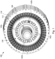
- FIG. 1 illustrates a first perspective view of a motor cooling system according to some embodiments of the present disclosure
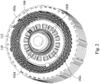
- Fig. 2 illustrates a second perspective view of a motor cooling system according to some embodiments of the present disclosure.
- a motor cooling system 100 includes a stator silicon steel sheet stacking structure 110 and a motor rotor cooling structure 150. When a motor is operating, the motor rotor cooling structure 150 is arranged radially inside the stator silicon steel sheet stacking structure 110 and rotatable.
- the motor rotor cooling structure 150 has two end plates (160, 180) at both ends in an axial direction.
- the end plate 160 has four nozzles (162a, 162b, 162c, 162d) distributed at equal intervals around the end plate 160.
- the end plate 180 has four nozzles (182a, 182b, 182c, 182d) distributed at equal intervals around the end plate 180.
- the four nozzles (162a, 162b, 162c, 162d) of the end plate 160 face inner-layered windings of the stator windings 112 of the stator silicon steel sheet stacking structure 110 on one side. These windings 112 are located between an inner circumference of the stator silicon steel sheet stacking structure 110 and the rotor.
- the four nozzles (182a, 182b, 182c, 182d) of the end plate 180 face inner-layered windings of the stator windings 112 of the stator silicon steel sheet stacking structure 110 on the other side.
- the cooling oil circulated within motor rotor cooling structure 150 is output to the inner-layered windings through the nozzles (162a, 162b, 162c, 162d, 182a, 182b, 182c, 182d) to enhance heat disspation for the stator silicon steel sheet stacking structure 110.
- a shaft 183 of the motor rotor cooling structure 150 includes an inner shaft 190 and an outer shaft 185 which are assembled together.
- the rotor 170 of the motor rotor cooling structure 150 is composed of a plurality of silicon steel sheets stacked in the axial direction.
- the stacked silicon steel sheets have respective shaft holes 170a aligned and connected with each other when the silicon steel sheets are stacked for the shaft 183 passing through, i.e., the shaft 183 passes through the stacked silicon steel sheet structure of the rotor 170 through the aligned and connected shaft holes 170a.
- Fig. 4 illustrates a cross-sectional view of a motor rotor cooling structure according to according to some embodiments of the present disclosure.
- the cooling oil is entered into the inner shaft 190 from an inner shaft oil inlet 192 at one end of the inner shaft 190 in the direction of the arrow, flowed toward the other end, and entered into the first flow channel 184 through at least one inner shaft oil outlet 194 of the inner shaft 190.
- the inner shaft 190 has four inner shaft oil outlets 194.
- the first flow channel 184 is a flow channel extending in the axial direction AD between the inner shaft 190 and the outer shaft 185.
- the cooling oil is then output from the first flow channel 184 to the second flow channel 187 through at least one outer shaft oil outlet 186 of the outer shaft 185.
- the second flow channel 187 is formed between concave grooves of the stacked silicon steel sheets of the rotor 170 and the outermost surface of the outer shaft 185. Therefore, when the cooling oil flows in the second flow channel 187, the heat disspation for the stacked silicon steel sheets of the rotor 170 is enhanced.
- the cooling oil flows from the outer shaft oil outlet 186 through the first flow channel 184 into the second flow channel 187, and then flows through the second flow channel 187 in the axial direction AD toward both ends of the shaft 183.
- the third flow channels 161 and the corresponding nozzles 162 are located on two opposite sides of the end plate 160 in the axial direction AD and connected to each other to be fluidly communicable
- the third flow channels 181 and the corresponding nozzles 182 are located on two opposite sides of the end plate 180 in the axial direction AD and connected to each other to be fluidly communicable.
- the nozzles (162, 182) are connected to the corresponding third flow channels (161, 181), so that the cooling oil is flowed through the first flow channel 184, the second flow channel 187, and the third flow channels (161, 181) in sequence, and then flowed through the nozzles (162, 182), and then output and sprayed to the inner-layered windings of the stator windings 112.
- each of the second flow channels 187 has a fixed width D1
- the third flow channels (161, 181) have multiple widths that are tapered from the end plate shaft hole (160a, 180a) to the outer circumference of the end plates (160, 180) in the radial direction RD
- the fixed width D1 of the second flow channel 187 is equal to a maximum width D2 of the third flow channels (161, 181) where the third flow channel is closest to the end plate shaft holes (160a, 180a) and intersected with the second flow channel 187, such that there is a smaller flow resistance for the cooling oil flowed through the second flow channel 187 in the axial direction AD and turned into the third flow channels (161 , 181) in the radial direction RD.
- the second flow channels 187 are formed between a plurality of concave grooves 175 of the stacked silicon steel sheets and the outer surface of the outer shaft 185 respectively. Therefore, the cooling oil flowing in the second flow channel 187 is farther from an outer circumference of the stacked silicon steel sheet than the magnet slot 172. Therefore, the cooling oil is basically flowed between the shaft 183 and the stacked silicon steel sheet, rather than flowed in the magnet slots 172 in conventional designs.
- the cooling oil flowing in the second flow channel 187 has a relatively small centrifugal force such that it is less likely for the cooling oil to leak from gaps between adjacent silicon steel sheets.
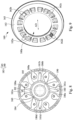
- a connection line (referring to the dotted line in the figure) between two outer shaft oil outlets (186a, 186c) is substantially perpendicular to a connection line (referring to the dotted line in the figure) between the other two outer shaft oil outlets (186b, 186d).
- the four outer shaft oil outlets (186a, 186b, 186c, 186d) of the outer shaft 185 are connected to four corresponding third flow channels (161a, 161b, 161c, 161d) to be fluidly communicable.
- the design of the tapered width of the third flow channel 161 fasiliates to increase the flow rate of the cooling oil when the motor rotor cooling structure 150 rotates, which is beneficial to increase the flow rate of the nozzles (162a, 162b, 162c, 162d) (please also refer to Fig. 5 or Fig. 9 ).
- the third flow channels 181 and shaft 183 of the other end plate 180 also have the same related designs and structures, and further figure and explanation is omitted.
- Fig. 9 illustrates a perspective view of an end plate 160 of a motor rotor cooling structure 150 according to some embodiments of the present disclosure.
- the four nozzles 162 of the end plate 160 are connected to the ends of the four third flow channels (161a, 161b, 161c, 161d) respectively in Figure 8 .
- the end plate 160 includes an annular end surface 163 and an annular inclined surface 165.
- the annular end surface 163 is connected to an outer circumference of the end plate shaft hole 160a.
- the annular inclined surface 165 is connected to an outer circumference of the annular end surface 163.
- the annular end surface 163 is generally perpendicular to the axial direction AD or generally perpendicular to the outer surface of the outer shaft 185 (please also refer to Fig. 5 ).
- the annular inclined surface 165 is inclined from the outer circumference of the annular end surface 163 toward an outer circumference of the end plate 160, and is not perpendicular to the axis AD, nor parallel to the outer surface of the outer shaft 185 (please also refer to Fig. 5 ) .
- the four nozzles (162a, 162b, 162c, 162d) are equally spaced on the annular inclined surface 165.
Landscapes
- Engineering & Computer Science (AREA)
- Power Engineering (AREA)
- Iron Core Of Rotating Electric Machines (AREA)
- Motor Or Generator Cooling System (AREA)
Applications Claiming Priority (2)
| Application Number | Priority Date | Filing Date | Title |
|---|---|---|---|
| US202363478990P | 2023-01-09 | 2023-01-09 | |
| CN202311132165.XA CN118316222A (zh) | 2023-01-09 | 2023-09-04 | 马达转子冷却结构 |
Publications (1)
| Publication Number | Publication Date |
|---|---|
| EP4398461A1 true EP4398461A1 (fr) | 2024-07-10 |
Family
ID=89223739
Family Applications (1)
| Application Number | Title | Priority Date | Filing Date |
|---|---|---|---|
| EP23217166.0A Pending EP4398461A1 (fr) | 2023-01-09 | 2023-12-15 | Structure de refroidissement de rotor d'un moteur |
Country Status (1)
| Country | Link |
|---|---|
| EP (1) | EP4398461A1 (fr) |
Citations (4)
| Publication number | Priority date | Publication date | Assignee | Title |
|---|---|---|---|---|
| DE102015223073A1 (de) * | 2015-11-23 | 2017-05-24 | Siemens Aktiengesellschaft | Elektromotor mit gekühlter Rotorwelle |
| US20200028412A1 (en) * | 2018-07-18 | 2020-01-23 | Aisin Aw Co., Ltd. | Structure for cooling rotating electrical machine and vehicle drive device |
| EP3934065A1 (fr) * | 2019-02-25 | 2022-01-05 | LG Magna e-Powertrain Co., Ltd. | Rotor et moteur électrique le comprenant |
| CN114598078A (zh) * | 2022-03-21 | 2022-06-07 | 珠海格力电器股份有限公司 | 电机转子组件、电机、车辆 |
-
2023
- 2023-12-15 EP EP23217166.0A patent/EP4398461A1/fr active Pending
Patent Citations (4)
| Publication number | Priority date | Publication date | Assignee | Title |
|---|---|---|---|---|
| DE102015223073A1 (de) * | 2015-11-23 | 2017-05-24 | Siemens Aktiengesellschaft | Elektromotor mit gekühlter Rotorwelle |
| US20200028412A1 (en) * | 2018-07-18 | 2020-01-23 | Aisin Aw Co., Ltd. | Structure for cooling rotating electrical machine and vehicle drive device |
| EP3934065A1 (fr) * | 2019-02-25 | 2022-01-05 | LG Magna e-Powertrain Co., Ltd. | Rotor et moteur électrique le comprenant |
| CN114598078A (zh) * | 2022-03-21 | 2022-06-07 | 珠海格力电器股份有限公司 | 电机转子组件、电机、车辆 |
Similar Documents
| Publication | Publication Date | Title |
|---|---|---|
| US11356000B2 (en) | Electric machine cooling with rotor having cooling pipe | |
| CN219717962U (zh) | 油冷电机及其定子铁芯 | |
| EP4239856B1 (fr) | Moteur électrique pour véhicule et véhicule | |
| US6798097B2 (en) | Stator cooling | |
| CN115741222B (zh) | 一种定子冷却结构和电主轴 | |
| EP4622069A1 (fr) | Moteur à champ magnétique axial et structure de refroidissement de celui-ci | |
| EP4398461A1 (fr) | Structure de refroidissement de rotor d'un moteur | |
| WO2024245682A1 (fr) | Ensemble rotor et moteur avec l'ensemble rotor | |
| CN116317361B (zh) | 一种用于油冷电机的电机轴、油冷电机及电动汽车 | |
| CN118316222A (zh) | 马达转子冷却结构 | |
| CN108964315A (zh) | 转子、电机及压缩机 | |
| US12170476B2 (en) | Motor rotor cooling system | |
| WO2026000856A1 (fr) | Moteur électrique | |
| CN115173602B (zh) | 转子组件、电机和车辆 | |
| CN118646186A (zh) | 液冷转子总成、电机和车辆 | |
| CN115498826A (zh) | 油冷电机 | |
| WO2022265009A1 (fr) | Boîtier de machine électrique tournante et machine électrique tournante | |
| US20260128650A1 (en) | Rotor | |
| JP2019097220A (ja) | 回転電機 | |
| CN223680829U (zh) | 定子组件及油冷电机 | |
| EP4539303A1 (fr) | Machine électrique | |
| US20240388166A1 (en) | Balancing disk for motor, rotor assembly, motor and vehicle | |
| CN221009881U (zh) | 电机的转子以及电机 | |
| CN222674013U (zh) | 一种电机 | |
| JP7716449B2 (ja) | 回転電機用ステータ |
Legal Events
| Date | Code | Title | Description |
|---|---|---|---|
| PUAI | Public reference made under article 153(3) epc to a published international application that has entered the european phase |
Free format text: ORIGINAL CODE: 0009012 |
|
| STAA | Information on the status of an ep patent application or granted ep patent |
Free format text: STATUS: REQUEST FOR EXAMINATION WAS MADE |
|
| 17P | Request for examination filed |
Effective date: 20231215 |
|
| AK | Designated contracting states |
Kind code of ref document: A1 Designated state(s): AL AT BE BG CH CY CZ DE DK EE ES FI FR GB GR HR HU IE IS IT LI LT LU LV MC ME MK MT NL NO PL PT RO RS SE SI SK SM TR |