EP4398480A1 - Magnetisches transportsystem, magnetische transportleitung und verfahren zur ansteuerung einer magnetischen transportleitung - Google Patents
Magnetisches transportsystem, magnetische transportleitung und verfahren zur ansteuerung einer magnetischen transportleitung Download PDFInfo
- Publication number
- EP4398480A1 EP4398480A1 EP22862966.3A EP22862966A EP4398480A1 EP 4398480 A1 EP4398480 A1 EP 4398480A1 EP 22862966 A EP22862966 A EP 22862966A EP 4398480 A1 EP4398480 A1 EP 4398480A1
- Authority
- EP
- European Patent Office
- Prior art keywords
- motor
- driving
- instruction
- transport line
- magnetic transport
- Prior art date
- Legal status (The legal status is an assumption and is not a legal conclusion. Google has not performed a legal analysis and makes no representation as to the accuracy of the status listed.)
- Pending
Links
Images




Classifications
-
- H—ELECTRICITY
- H02—GENERATION; CONVERSION OR DISTRIBUTION OF ELECTRIC POWER
- H02P—CONTROL OR REGULATION OF ELECTRIC MOTORS, ELECTRIC GENERATORS OR DYNAMO-ELECTRIC CONVERTERS; CONTROLLING TRANSFORMERS, REACTORS OR CHOKE COILS
- H02P25/00—Arrangements or methods for the control of AC motors characterised by the kind of AC motor or by structural details
- H02P25/02—Arrangements or methods for the control of AC motors characterised by the kind of AC motor or by structural details characterised by the kind of motor
- H02P25/06—Linear motors
-
- B—PERFORMING OPERATIONS; TRANSPORTING
- B65—CONVEYING; PACKING; STORING; HANDLING THIN OR FILAMENTARY MATERIAL
- B65G—TRANSPORT OR STORAGE DEVICES, e.g. CONVEYORS FOR LOADING OR TIPPING, SHOP CONVEYOR SYSTEMS OR PNEUMATIC TUBE CONVEYORS
- B65G54/00—Non-mechanical conveyors not otherwise provided for
- B65G54/02—Non-mechanical conveyors not otherwise provided for electrostatic, electric, or magnetic
-
- B—PERFORMING OPERATIONS; TRANSPORTING
- B61—RAILWAYS
- B61B—RAILWAY SYSTEMS; EQUIPMENT THEREFOR NOT OTHERWISE PROVIDED FOR
- B61B13/00—Other railway systems
- B61B13/12—Systems with propulsion devices between or alongside the rails, e.g. pneumatic systems
-
- B—PERFORMING OPERATIONS; TRANSPORTING
- B65—CONVEYING; PACKING; STORING; HANDLING THIN OR FILAMENTARY MATERIAL
- B65G—TRANSPORT OR STORAGE DEVICES, e.g. CONVEYORS FOR LOADING OR TIPPING, SHOP CONVEYOR SYSTEMS OR PNEUMATIC TUBE CONVEYORS
- B65G43/00—Control devices, e.g. for safety, warning or fault-correcting
-
- H—ELECTRICITY
- H02—GENERATION; CONVERSION OR DISTRIBUTION OF ELECTRIC POWER
- H02P—CONTROL OR REGULATION OF ELECTRIC MOTORS, ELECTRIC GENERATORS OR DYNAMO-ELECTRIC CONVERTERS; CONTROLLING TRANSFORMERS, REACTORS OR CHOKE COILS
- H02P25/00—Arrangements or methods for the control of AC motors characterised by the kind of AC motor or by structural details
- H02P25/02—Arrangements or methods for the control of AC motors characterised by the kind of AC motor or by structural details characterised by the kind of motor
- H02P25/06—Linear motors
- H02P25/064—Linear motors of the synchronous type
-
- H—ELECTRICITY
- H02—GENERATION; CONVERSION OR DISTRIBUTION OF ELECTRIC POWER
- H02P—CONTROL OR REGULATION OF ELECTRIC MOTORS, ELECTRIC GENERATORS OR DYNAMO-ELECTRIC CONVERTERS; CONTROLLING TRANSFORMERS, REACTORS OR CHOKE COILS
- H02P29/00—Arrangements for regulating or controlling electric motors, appropriate for both AC and DC motors
- H02P29/02—Providing protection against overload without automatic interruption of supply
- H02P29/024—Detecting a fault condition, e.g. short circuit, locked rotor, open circuit or loss of load
- H02P29/028—Detecting a fault condition, e.g. short circuit, locked rotor, open circuit or loss of load the motor continuing operation despite the fault condition, e.g. eliminating, compensating for or remedying the fault
Definitions
- Magnetic transport lines typically include an actuating mechanism that operates under the drive of the driving system and a driving system to achieve automatic transport.
- the predominant actuating mechanism utilized is the linear motor, where the motor mover is composed of a coil (relatively short), and the motor stator (relatively long) is composed of alternately arranged permanent magnets. Due to the nature of linear motors in these technical solutions, the motor mover needs to be powered through wires supplying the coils, requiring trailing cables. This limitation poses practical challenges in practical applications.
- the present invention aims to provide a magnetic transport line drive system and a method thereof to address the above-mentioned technical problems in the existing solutions, thereby reducing system latency, improving response speed, decreasing the complexity of the driving system wiring, and under the condition of effectively controlling hardware requirements and costs of the magnetic transport line driving system, the system structure has been simplified, and the efficiency and reliability of the system have been improved.
- the motor driving unit comprises:
- the motor driving unit further comprises: a fault processing module, which determines whether there is a fault that affects the operation of the magnetic transport line based on the speed information and position information of the motor mover in the magnetic transport line, as well as the current information of each phase of the motor stator, and outputting a shutdown instruction to the power driving inversion module when the fault occurs.
- a fault processing module which determines whether there is a fault that affects the operation of the magnetic transport line based on the speed information and position information of the motor mover in the magnetic transport line, as well as the current information of each phase of the motor stator, and outputting a shutdown instruction to the power driving inversion module when the fault occurs.
- the motor control unit comprises:
- the motor control unit further comprises:
- the motion control unit comprises
- multiple loops formed by connecting multiple position sensing units in series in parallel as well as multiple loops formed by connecting multiple motor driving units in series in parallel in the magnetic transport line driving system.
- the magnetic transport line driving system further comprises: a swapping control unit, used for transmitting data between the motor control unit and the position sensing unit, and/or the motor driving unit on each loop based on the motor stator selection instruction
- the present invention also provides a magnetic transport line, which comprises an actuating mechanism, includes multiple motor stators, and at least one motor mover, wherein the magnetic transport line further comprises a magnetic transport line driving system as claimed in any one of the preceding claims.
- the present invention also provides a control method for a magnetic transport line driving system, controlled based on the effective shaft, used to drive the actuating mechanism of the magnetic transport line according to the instruction, the actuating mechanism comprises multiple motor stators and at least one motor mover, wherein the control method comprises:
- control method further comprises: collision detection step, determining whether the driving instruction will cause a collision of the motor movers, in case the result of the determination is negative, the driving instruction is outputted, and in the case where the determination result is positive, it waits until the determination result is negative before outputting the driving instruction.
- collision detection step determining whether the driving instruction will cause a collision of the motor movers, in case the result of the determination is negative, the driving instruction is outputted, and in the case where the determination result is positive, it waits until the determination result is negative before outputting the driving instruction.
- control method further comprises: computing resource scheduling step, allocating the required computing resource for the control loop calculation step based on the motor stator selection instruction.
- Fig. 3 to 6 illustrate a preferred embodiment of the magnetic transport line driving system in the present invention.
- FIG. 3 illustrates a block schematic diagram of the magnetic transport line driving system in the present invention.
- a magnetic transport line driving system 200 is provided for driving an actuating mechanism 100 of the magnetic transport line according to the instruction, the magnetic transport line driving system comprises:
- the ports of the drive communication module 231 can be configured with one or more network ports or optical ports, enabling multiple motor driving units 230 to be connected in series by forming mutual interconnections.
- the communication of the drive communication module 231 only includes input: 1) inversion setting 2) system control, output: 1) current and state feedback.
- the communication cycle is set to the calculation cycle of the current loop, which, in one embodiment, is 50 microseconds. Therefore, the communication format of the motor driving unit is simple, and the intervals are very short, contributing to enhanced system reliability and fault detection characteristics.
- the power driving inversion module 233 generates and provides driving current to the specified motor stator 110 based on the inversion control waveform.
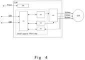
- the motor driving unit 230 further comprises a fault processing module 235, which determines whether there is a fault that affects the operation of the magnetic transport line based on the speed information, position information of the motor mover, and the current information of each phase of the motor stator in the magnetic transport line, such as over-deviation faults. In the event of a fault, the fault processing module issues a shutdown instruction to the power driving inversion module 233.
- the motor driving unit 230 further comprises a power management module 236 for managing all power supplies within the motor driving unit 230, including internal modules and power driving power.
- the drive communication module 231, waveform generation module 232, collection module 234, and fault processing module 235 can be integrated into one main control chip.
- the main control chip is a small-capacity FPGA chip.
- multiple motor driving units 230 can be integrated onto a single PCB board, and the cost and system complexity can be further reduced by sharing the power management module 236 and the drive communication module 231.
- the motor driving unit in the present invention does not require the use of expensive DSP and large-capacity FPGA in existing technical solutions.
- the number of chips and other electronic components is also significantly reduced, resulting in both cost reduction and increased reliability.
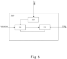
- At least one motor computing module 224 generates and outputs an inversion setting instruction to the motor driving unit 230 based on the driving instruction, motor stator selection instruction, and the current information of each phase in the motor stator 110 provided by the motor driving unit 230.
- the motor computing module 224 can also perform compensation calculations for the disturbance of the magnetic transport line, such as static friction force, dynamic friction force, cogging force, and the like.
- the motor control unit 220 further comprises: A computing resource scheduling and allocating module 225 selects one or more motor computing modules 224 based on the motor stator selection instruction so that the selected motor computing module 224 completes the calculation; by employing the computing resource scheduling and allocating module 225, time-division multiplexing of the motor computing module 224 can be achieved. For example, One control cycle can accomplish calculations for 16 effective shafts.
- the motion control unit 210 further comprises: A motor stator management module 213 for managing the motor stator 110 of the system.
- a motor stator management module 213 for managing the motor stator 110 of the system.
- external motor stators When external motor stators are added, they provide feedback to the program execution module, allocate resources, and instruct programs accordingly.
- internal motor stators exit the system it offers feedback to the program execution module, facilitating the recovery and reallocation of resource and program instruction.
- each motor driving unit 230 and position sensor 240 include a superior communication port and a subordinate communication port (Ethernet or optical fiber), which form a loop.
- the motor control unit 220 sends communication packets with enumeration instruction through the upper-level communication port, initiating the enumeration of addresses.
- the first motor driving unit 230/position sensor 240 has the address 1, the next one is 2, and so forth. This continues until the last motor driving unit 230/position sensor 240 is reached, at which point the information is returned to the motor control unit 220.
- all loops in the system require unified addressing, and the addresses on each loop are continuous.
- the address ranges of different loops are different, and each loop, that is, the address of each motor shaft on the system, is unique. For example: Loop sequence number Address range Loop 1 1-80 Loop 2 81-160 Loop 3 161-240
- the magnetic transport line driving system may also comprise: a swapping control unit 250 for transmitting data between the motor control unit 220 and the position sensing unit 240 and/or the motor driving unit 230 on each loop based on motor stator selection instruction.
- the swapping control unit 250 recognizes the address information of the packet header and sends the packet to the corresponding motor driving unit 230 and position sensor 240 on the loop.
- the data packets returned by the corresponding loop can also be returned to the motor control unit 220 through the fastest channel.
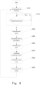
- Step S300 effective shaft address calculation step
- motor control unit 220 calculates the quantity information and address information of effective shafts based on the quantity information and position information of the motor mover.
- Step S600 driving current generation step
- the motor control unit 220 stores the inversion setting instruction and selects the corresponding motor stator according to the motor stator selection instruction.
- the corresponding motor driving unit 230 generates the driving current for the motor stator.
- the motor driving unit 230 simultaneously feeds back the actual motor current to the current loop, and the angular displacement or linear position generated by the motor rotation is fed back to the speed loop and position loop.
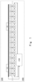
- a preferred embodiment of the magnetic transport line provided by the present invention comprises: A magnetic transport line with a length of 5 meters, consists of 16 motor shafts per meter, with three movers moving reciprocally along the magnetic transport line. Therefore, the actuating mechanism of the magnetic transport line includes 80 motor stators and 3 motor movers, with a maximum effective shaft count of 10, approximately 12.5% of the total shaft count.
- the driving system comprises:
- Every 4 motor driving units are integrated into one motor drive board, with a total of 20 motor drive boards.
- each motion controller integrates one motion control unit and one motor control unit.
- the motion control unit comprises a program execution module
Landscapes
- Engineering & Computer Science (AREA)
- Power Engineering (AREA)
- Chemical & Material Sciences (AREA)
- Combustion & Propulsion (AREA)
- Transportation (AREA)
- Mechanical Engineering (AREA)
- Control Of Linear Motors (AREA)
- Control Of Multiple Motors (AREA)
- Control Of Conveyors (AREA)
Applications Claiming Priority (2)
| Application Number | Priority Date | Filing Date | Title |
|---|---|---|---|
| CN202111025731.8A CN113726262B (zh) | 2021-09-02 | 2021-09-02 | 一种磁输送线驱动系统、磁输送线和磁输送线驱动方法 |
| PCT/CN2022/108201 WO2023029825A1 (zh) | 2021-09-02 | 2022-07-27 | 一种磁输送线驱动系统、磁输送线和磁输送线驱动方法 |
Publications (2)
| Publication Number | Publication Date |
|---|---|
| EP4398480A1 true EP4398480A1 (de) | 2024-07-10 |
| EP4398480A4 EP4398480A4 (de) | 2025-10-08 |
Family
ID=78680966
Family Applications (1)
| Application Number | Title | Priority Date | Filing Date |
|---|---|---|---|
| EP22862966.3A Pending EP4398480A4 (de) | 2021-09-02 | 2022-07-27 | Magnetisches transportsystem, magnetische transportleitung und verfahren zur ansteuerung einer magnetischen transportleitung |
Country Status (5)
| Country | Link |
|---|---|
| US (1) | US20240367695A1 (de) |
| EP (1) | EP4398480A4 (de) |
| JP (1) | JP7847204B2 (de) |
| CN (1) | CN113726262B (de) |
| WO (1) | WO2023029825A1 (de) |
Families Citing this family (3)
| Publication number | Priority date | Publication date | Assignee | Title |
|---|---|---|---|---|
| CN113726262B (zh) * | 2021-09-02 | 2024-04-19 | 上海捷勃特机器人有限公司 | 一种磁输送线驱动系统、磁输送线和磁输送线驱动方法 |
| CN115940706A (zh) * | 2022-12-07 | 2023-04-07 | 瑞声科技(南京)有限公司 | 一种直驱传输系统及控制方法 |
| CN118894375B (zh) * | 2024-07-25 | 2025-08-26 | 果栗智造(上海)技术股份有限公司 | 一种动子防碰撞控制方法、装置及磁驱电机输送系统 |
Family Cites Families (21)
| Publication number | Priority date | Publication date | Assignee | Title |
|---|---|---|---|---|
| GB8804991D0 (en) * | 1988-03-02 | 1988-03-30 | Williams Fairey Eng Ltd | Improvements in electric motors |
| JP2618138B2 (ja) * | 1991-11-06 | 1997-06-11 | 三菱電機株式会社 | ロープレスエレベータ装置 |
| JPH05199616A (ja) * | 1992-01-17 | 1993-08-06 | Fujitsu Ltd | 搬送装置の制御装置 |
| JP3501559B2 (ja) * | 1995-06-27 | 2004-03-02 | キヤノン株式会社 | リニア・モータ装置 |
| US7194321B2 (en) * | 2004-10-29 | 2007-03-20 | Dynacity Technology (Hk) Limited | Modular multi-axis motion control and driving system and method thereof |
| JP5177193B2 (ja) | 2009-10-29 | 2013-04-03 | 株式会社安川電機 | リニアモータ制御装置 |
| US8996161B2 (en) * | 2011-05-19 | 2015-03-31 | Rockwell Automation, Inc. | Controlled architecture for transport systems |
| US9511681B2 (en) * | 2013-05-09 | 2016-12-06 | Rockwell Automation, Inc. | Controlled motion system having an improved track configuration |
| JP6313642B2 (ja) * | 2014-04-18 | 2018-04-18 | キヤノン株式会社 | リニアモータ制御装置及びリニアモータ制御システム |
| EP3045399B1 (de) * | 2015-01-19 | 2017-06-28 | Cama1 S.p.A. | Eine Verpackungsmaschine mit einem magnetischen Förderband |
| JP6733170B2 (ja) | 2015-08-21 | 2020-07-29 | 村田機械株式会社 | リニアモータシステム |
| CN105600469B (zh) * | 2016-01-21 | 2018-08-31 | 东莞思谷数字技术有限公司 | 一种基于电磁驱动和传感模块的可组装自动化运输系统 |
| DE102018118814B4 (de) * | 2018-08-02 | 2024-07-18 | Beckhoff Automation Gmbh | Verfahren zum Identifizieren eines Schlittens eines linearen Transportsystems |
| DE102018129727A1 (de) * | 2018-11-26 | 2020-05-28 | Beckhoff Automation Gmbh | Vorrichtung und Verfahren zum Vermeiden einer Kollision beim Antreiben von wenigstens zwei Movern auf einer Antriebsfläche |
| EP3661033A1 (de) * | 2018-11-27 | 2020-06-03 | B&R Industrial Automation GmbH | Transporteinrichtung in form eines langstatorlinearmotors |
| CN210536535U (zh) * | 2018-11-29 | 2020-05-15 | 实时侠智能控制技术有限公司 | 一种远程分离的电机驱动及电机控制系统以及电机驱动及电机控制系统 |
| CN109302103A (zh) * | 2018-11-29 | 2019-02-01 | 上海福赛特控制技术有限公司 | 一种远程分离的电机驱动及电机控制系统 |
| CN112027676B (zh) * | 2019-06-03 | 2022-05-10 | 上海铼钠克数控科技有限公司 | 长定子输送系统的动子控制方法及控制系统 |
| US10985685B1 (en) | 2019-09-30 | 2021-04-20 | Rockwell Automation Technologies, Inc. | System and method for wireless power transfer in a linear cart system |
| CN114641441B (zh) * | 2019-11-01 | 2024-04-09 | 平田机工株式会社 | 移动台、基座单元以及移动单元 |
| CN113726262B (zh) * | 2021-09-02 | 2024-04-19 | 上海捷勃特机器人有限公司 | 一种磁输送线驱动系统、磁输送线和磁输送线驱动方法 |
-
2021
- 2021-09-02 CN CN202111025731.8A patent/CN113726262B/zh active Active
-
2022
- 2022-07-27 WO PCT/CN2022/108201 patent/WO2023029825A1/zh not_active Ceased
- 2022-07-27 JP JP2024514357A patent/JP7847204B2/ja active Active
- 2022-07-27 EP EP22862966.3A patent/EP4398480A4/de active Pending
- 2022-07-27 US US18/688,787 patent/US20240367695A1/en active Pending
Also Published As
| Publication number | Publication date |
|---|---|
| WO2023029825A1 (zh) | 2023-03-09 |
| EP4398480A4 (de) | 2025-10-08 |
| CN113726262B (zh) | 2024-04-19 |
| JP7847204B2 (ja) | 2026-04-16 |
| US20240367695A1 (en) | 2024-11-07 |
| CN113726262A (zh) | 2021-11-30 |
| JP2024532519A (ja) | 2024-09-05 |
Similar Documents
| Publication | Publication Date | Title |
|---|---|---|
| EP4398480A1 (de) | Magnetisches transportsystem, magnetische transportleitung und verfahren zur ansteuerung einer magnetischen transportleitung | |
| CN108638066B (zh) | 一种用于机器人的传送带同步跟踪的装置、方法及系统 | |
| JP6023059B2 (ja) | 一体型サーボシステム、モーターシステム及び一体型サーボシステムの制御方法 | |
| CN103019169A (zh) | 伺服驱动系统 | |
| CN109687782A (zh) | 一种步进电机的控制装置和控制系统 | |
| CN104052341A (zh) | 生成预加载转矩值的电动机控制装置 | |
| US9434075B2 (en) | Method for operating a multi-limb manipulator | |
| US9588508B2 (en) | Master device that changes data communication speed in accordance with the number of slave devices | |
| US20250270053A1 (en) | Transport system | |
| CN111381612A (zh) | 一种基于can总线的多轴同步控制系统及方法 | |
| US8952636B2 (en) | Data communication device that carries out serial communication in order to control motor | |
| CN205000096U (zh) | 一种缝纫机送料控制系统 | |
| JP2002272184A (ja) | 電動機の駆動制御装置 | |
| CN108983699A (zh) | 基于plc的三轴数控钻床控制系统及其控制方法 | |
| CA3084178A1 (en) | Method for configuring a planar drive system | |
| CN110168455B (zh) | 多计算核设备上的技术过程的控制 | |
| CN100524136C (zh) | 驱动控制系统及机械控制装置 | |
| CN108302022B (zh) | 一种隔膜泵相位角的控制方法及装置 | |
| CN110703687A (zh) | 一种误差补偿系统及方法 | |
| JP2004227261A (ja) | 数値制御システム | |
| CN109768738A (zh) | 电动机控制装置、控制系统以及电动机控制方法 | |
| JP4999144B2 (ja) | サーボモータ駆動装置 | |
| CN108549026A (zh) | 多轴控制系统的同步性能检测方法、装置和系统 | |
| JP7746890B2 (ja) | サーボシステム | |
| CN117955363A (zh) | 一种基于fpga的高精度调频驱动超声电机控制器 |
Legal Events
| Date | Code | Title | Description |
|---|---|---|---|
| STAA | Information on the status of an ep patent application or granted ep patent |
Free format text: STATUS: THE INTERNATIONAL PUBLICATION HAS BEEN MADE |
|
| PUAI | Public reference made under article 153(3) epc to a published international application that has entered the european phase |
Free format text: ORIGINAL CODE: 0009012 |
|
| STAA | Information on the status of an ep patent application or granted ep patent |
Free format text: STATUS: REQUEST FOR EXAMINATION WAS MADE |
|
| 17P | Request for examination filed |
Effective date: 20240326 |
|
| AK | Designated contracting states |
Kind code of ref document: A1 Designated state(s): AL AT BE BG CH CY CZ DE DK EE ES FI FR GB GR HR HU IE IS IT LI LT LU LV MC MK MT NL NO PL PT RO RS SE SI SK SM TR |
|
| DAV | Request for validation of the european patent (deleted) | ||
| DAX | Request for extension of the european patent (deleted) | ||
| A4 | Supplementary search report drawn up and despatched |
Effective date: 20250908 |
|
| RIC1 | Information provided on ipc code assigned before grant |
Ipc: H02P 25/06 20160101AFI20250902BHEP Ipc: B65G 54/02 20060101ALI20250902BHEP Ipc: H02P 29/028 20160101ALI20250902BHEP Ipc: H02P 25/064 20160101ALI20250902BHEP |