EP4398521B1 - Dispositif de réseau pour restaurer une opération poe - Google Patents
Dispositif de réseau pour restaurer une opération poe Download PDFInfo
- Publication number
- EP4398521B1 EP4398521B1 EP23160905.8A EP23160905A EP4398521B1 EP 4398521 B1 EP4398521 B1 EP 4398521B1 EP 23160905 A EP23160905 A EP 23160905A EP 4398521 B1 EP4398521 B1 EP 4398521B1
- Authority
- EP
- European Patent Office
- Prior art keywords
- relay
- terminal
- coupled
- network
- poe
- Prior art date
- Legal status (The legal status is an assumption and is not a legal conclusion. Google has not performed a legal analysis and makes no representation as to the accuracy of the status listed.)
- Active
Links
Images


Classifications
-
- H—ELECTRICITY
- H04—ELECTRIC COMMUNICATION TECHNIQUE
- H04L—TRANSMISSION OF DIGITAL INFORMATION, e.g. TELEGRAPHIC COMMUNICATION
- H04L12/00—Data switching networks
- H04L12/02—Details
- H04L12/10—Current supply arrangements
Definitions
- the present invention is related to a network device capable of providing PoE power paths in the Ethernet mode without influencing its Ethernet communication.
- PoE Power over Ethernet
- VoIP voice over Internet Protocol
- WAPs wireless access points
- IP Internet Protocol
- PoE-capable devices can function without an electrical outlet, it can greatly simplify the amount and cost of infrastructure an organization has to manage.
- PoE technology is widely adopted in IP surveillance and remote-monitor applications. Because PoE cameras receive their power through an Ethernet cable, there's no need to install them near electrical outlets, which provides many practical advantages such as greater flexibility for camera placement, reduced maintenance, simpler management, lower installation cost, better scalability, better power reliability, better network reliability and increased system safety.
- a connection is maintained between a pair of Ethernet ports that have circuitry connected in series with the ports and receiving PoE from one of the ports, by providing a controllable bypass circuit coupled to the pair of Ethernet ports in parallel with the circuitry receiving PoE, sensing a preselected condition, and opening and closing the bypass circuit in response to the presence or absence of the preselected condition.
- Power sourcing equipment PSE
- the circuitry may also supply the switch with a control signal in response to the detection of the preselected condition.
- the present invention which aims at providing a network device which restores the PoE operation, is defined in the appended independent claim 1 to which reference should be made.
- Advantageous features are set out in the appended dependent claims.
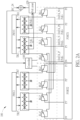
- FIG. 1 is a functional diagram illustrating an existing PoE system.
- the PoE system normally includes one power sourcing equipment (PSE) and multiple powered devices (PDs) each including a controller and at least one port.
- the controller of the PSE is coupled to an external network, a power source and multiple ports.
- the external network can provide network data, and the power source can supply power to the PSE.
- Each port of the PSE is coupled to a port of a corresponding PD for transmitting power and network data to the corresponding PD.
- the controller of the PSE is configured to execute a specific power management algorithm so as to transmit the electricity received from the power source and the network data received from the external network by each port to a corresponding PD and calculate the remaining power quota of the PSE for determining whether there is sufficient electricity to power other PDs.
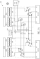
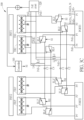
- FIGs. 2A and 2B are diagrams illustrating an implementation and operation of a prior art network device 100 capable of providing Ethernet bypass and PoE functions.
- the network device 100 includes physical layer transceivers PHY1 and PHY2, network transformers TR1-TR2 and TR1'-TR2', a plurality of relays RL1-RL4 and RL1'-RL4', network ports PORT1 and PORT2, a controller 110, and a PoE powered circuit 120.
- the network device 300 may be an Ethernet powered device such as an Ethernet switch, an Ethernet hub, or an Ethernet injector.
- an Ethernet powered device such as an Ethernet switch, an Ethernet hub, or an Ethernet injector.
- the type of the network device 300 does not limit the scope of the present invention.
Landscapes
- Engineering & Computer Science (AREA)
- Computer Networks & Wireless Communication (AREA)
- Signal Processing (AREA)
- Small-Scale Networks (AREA)
- Selective Calling Equipment (AREA)
- Mobile Radio Communication Systems (AREA)
Claims (8)
- Dispositif de réseau (300) pour restaurer le fonctionnement de l'alimentation par Ethernet, PoE, comprenant:un premier port de réseau (PORT1) qui comprend une première broche (P1), une deuxième broche (P2), une troisième broche (P3) et une quatrième broche (P4);un circuit PoE (320) configuré pour fournir de l'énergie après avoir reçu un premier signal d'alimentation (PoE+) via le premier port de réseau (PORT1) dans un mode de contournement Ethernet dans lequel un chemin de transmission pour les signaux de données est fourni entre le premier port de réseau (PORT1) et un autre port de réseau indépendant lorsqu'aucune alimentation n'est fournie au dispositif de réseau (300);un premier transformateur de réseau (TR1);un deuxième transformateur de réseau (TR2);un premier relais (RL1) couplé au premier transformateur de réseau (TR1) et au premier port de réseau (PORT1), et comprenant:une première borne couplée à la première broche (P1);une deuxième borne couplée au premier transformateur de réseau (TR1); etune troisième borne;un deuxième relais (RL2) couplé au premier transformateur de réseau (TR1) et au premier port de réseau (PORT1), et comprenant:une première borne couplée à la deuxième broche (P2);une deuxième borne couplée au premier transformateur de réseau (TR1); etune troisième borne;un troisième relais (RL3) couplé au deuxième transformateur de réseau (TR2) et au premier port de réseau (PORT1), et comprenant:une première borne couplée à la troisième broche (P3);une deuxième borne couplée au deuxième transformateur de réseau (TR2); etune troisième borne; etun quatrième relais (RL4) couplé au deuxième transformateur de réseau (TR2) et au premier port de réseau (PORT1), et comprenant:une première borne couplée à la quatrième broche (P4);une deuxième borne couplée au deuxième transformateur de réseau (TR2); etune troisième borne;un premier inducteur (L1) couplé au premier relais (RL1) et au circuit PoE (320) et configuré pour transmettre le premier signal d'alimentation (PoE+) reçu par le premier port de réseau (PORT1) au circuit PoE (320);un deuxième inducteur (L2) couplé au deuxième relais (RL2) et au circuit PoE (320) et configuré pour transmettre le premier signal d'alimentation (PoE+) reçu par le premier port de réseau (PORT1) au circuit PoE (320);un troisième inducteur (L3) couplé au troisième relais (RL3) et au circuit PoE (320) et configuré pour transmettre un deuxième signal d'alimentation (PoE-) fourni par le circuit PoE (320) au premier port de réseau (PORT1);un quatrième inducteur (L4) couplé au quatrième relais (RL4) et au circuit PoE (320) et configuré pour transmettre le deuxième signal d'alimentation (PoE-) fourni par le circuit PoE (320) au premier port de réseau (PORT1); etun contrôleur (310) configuré pour commuter les états opérationnels du premier au quatrième relais (RL1-RL4) lorsqu'il est alimenté par le circuit PoE (320) en mode de contournement Ethernet, dans lequel, après que le premier signal d'alimentation (PoE+) reçu par le premier port de réseau (PORT1) est transmis au circuit PoE (320) via le premier inducteur (L1) et le deuxième inducteur (L2) lorsque les premier à quatrième relais (RL1-RL4) sont dans le deuxième état de sorte que le circuit PoE (320) commence à alimenter le contrôleur (310), le contrôleur (310) est en outre configuré pour:émettre un premier signal de commande (S1) au premier relais (RL1) à un premier moment pour commuter le premier relais (RL1) au premier état;émettre le premier signal de commande (S1) au troisième relais (RL3) au premier moment pour commuter le troisième relais (RL3) au premier état;émettre un deuxième signal de commande (S2) au deuxième relais (RL2) à un deuxième moment pour la commutation du deuxième relais (RL2) au premier état; etémettre le deuxième signal de commande (S2) au quatrième relais (RL4) au deuxième moment pour la commutation du quatrième relais (RL4) au premier état, le deuxième moment se produisant après le premier moment.
- Dispositif de réseau (300) de la revendication 1, dans lequelle contrôleur (110, 310) est en outre configuré pour émettre un premier signal de commande (S1) au premier relais (RL1) et au troisième relais (RL3) et émettre un deuxième signal de commande (S2) au deuxième relais (RL2) et au quatrième relais (RL4) lorsqu'il est alimenté par le circuit PoE (320) en mode de contournement Ethernet;le premier relais (RL1) est configuré pour:fonctionner dans un premier état lorsqu'il reçoit le premier signal de commande (S1) de manière à coupler la première extrémité du premier relais (RL1) à la deuxième extrémité du premier relais (RL1); etfonctionner dans un deuxième état lorsqu'il ne reçoit pas le premier signal de commande (S1) de manière à coupler la première extrémité du premier relais (RL1) à la troisième extrémité du premier relais (RL1);le deuxième relais (RL2) est configuré pour:fonctionner dans le premier état lorsqu'il reçoit le deuxième signal de commande (S2) de manière à coupler la première extrémité du deuxième relais (RL2) à la deuxième extrémité du deuxième relais (RL2); etfonctionner dans le deuxième état lorsqu'il ne reçoit pas le deuxième signal de commande (S2) de manière à coupler la première extrémité du deuxième relais (RL2) à la troisième extrémité du deuxième relais (RL2);le troisième relais (RL3) est configuré pour:fonctionner dans le premier état lorsqu'il reçoit le premier signal de commande (S1) de manière à coupler la première extrémité du troisième relais (RL3) à la deuxième extrémité du troisième relais (RL3); etfonctionner dans le deuxième état lorsqu'il ne reçoit pas le premier signal de commande (S1) de manière à coupler la première extrémité du troisième relais (RL3) à la troisième extrémité du troisième relais (RL3);le quatrième relais (RL4) est configuré pour:fonctionner dans le premier état lorsqu'il reçoit le deuxième signal de commande (S2) de manière à coupler la première extrémité du quatrième relais (RL4) à la deuxième extrémité du quatrième relais (RL4); etfonctionner dans le deuxième état lorsqu'il ne reçoit pas le deuxième signal de commande (S2) de manière à coupler la première extrémité du quatrième relais (RL4) à la troisième extrémité du quatrième relais (RL4); etle premier relais (RL1), le deuxième relais (RL2), le troisième relais (RL3) et le quatrième relais (RL4) sont configurés pour fonctionner dans le deuxième état en mode de contournement Ethernet.
- Dispositif de réseau (300) de l'une des revendications 1-2, dans lequelle premier inducteur (L1) comprend:une première extrémité couplée à la troisième borne du premier relais (RL1); etune deuxième extrémité couplée au circuit PoE (320);le deuxième inducteur (L2) comprend:une première extrémité couplée à la troisième borne du deuxième relais (RL2); etune deuxième extrémité couplée au circuit PoE (320);le troisième inducteur (L3) comprend:une première extrémité couplée à la troisième borne du troisième relais (RL3); etune deuxième extrémité couplée au circuit PoE (320); etle quatrième inducteur (L4) comprend:une première extrémité couplée à la troisième borne du quatrième relais (RL4); etune deuxième extrémité couplée au circuit PoE (320).
- Dispositif de réseau (300) de la revendication 1, dans lequelle premier signal d'alimentation (PoE+) reçu par le premier port de réseau (PORT1) est transmis au circuit PoE (320) séquentiellement via la première borne du premier relais (RL1), la deuxième borne du premier relais (RL1) et le premier transformateur de réseau (TR1) entre le premier point temporel et le deuxième point temporel de sorte que le circuit PoE (320) fournisse le deuxième signal d'alimentation (PoE-) en conséquence; etle deuxième signal d'alimentation (PoE-) est transmis à la troisième broche (P3) du premier port de réseau (PORT1) séquentiellement via le deuxième transformateur de réseau (TR2), la deuxième borne du troisième relais (RL3) et la première borne du troisième relais (RL3) entre le premier et le deuxième point dans le temps.
- Dispositif de réseau (300) de la revendication 4, dans lequelle premier signal d'alimentation (PoE+) reçu par le premier port de réseau (PORT1) est transmis au circuit PoE (320) via le premier relais (RL1), le deuxième relais (RL2) et le premier transformateur de réseau (TR1) après le deuxième point temporel afin que le circuit PoE (320) fournisse le deuxième signal d'alimentation (PoE-) en conséquence; etle deuxième signal d'alimentation (PoE-) est transmis au premier port de réseau (PORT1) via le deuxième transformateur de réseau (TR2), le troisième relais (RL3) et le quatrième relais (RL4) après le deuxième point de temps.
- Dispositif de réseau (300) de l'une des revendications 1 à 5, comprenant en outre:un deuxième port de réseau (PORT2) qui comprend une cinquième broche (P1'), une sixième broche (P2'), une septième broche (P3') et une huitième broche (P4');un troisième transformateur de réseau (TR1');un quatrième transformateur de réseau (TR2');un cinquième relais (RL1') comprenant:une première borne couplée à la cinquième broche (P1');une deuxième borne couplée au troisième transformateur de réseau (TR1'); etune troisième borne;un sixième relais (RL2') comprenant:une première borne couplée à la sixième broche (P2');une deuxième borne couplée au troisième transformateur de réseau (TR1'); etune troisième borne;un septième relais (RL3') comprenant:une première borne couplée à la septième broche (P3');une deuxième borne couplée au quatrième transformateur de réseau (TR2'); etune troisième borne; etun huitième relais (RL4') comprenant:une première borne couplée à la huitième broche (P4');une deuxième borne couplée au quatrième transformateur de réseau (TR2'); etune troisième borne;un premier condensateur (C1) couplé entre la troisième borne du premier relais (RL1) et la troisième borne du cinquième relais (RL1');un deuxième condensateur (C2) couplé entre la troisième borne du deuxième relais (RL2) et la troisième borne du sixième relais (RL2');un troisième condensateur (C3) couplé entre la troisième borne du troisième relais (RL3) et la troisième borne du septième relais (RL3'); etun quatrième condensateur (C4) couplé entre la troisième borne du quatrième relais (RL4) et la troisième borne du huitième relais (RL4').
- Dispositif de réseau (300) de la revendication 6, dans lequelun premier signal de données (DATA_N) reçu par la première broche (P1) du premier port de réseau (PORT1) est transmis à la cinquième broche (P1') du deuxième port de réseau (PORT2) séquentiellement via la première borne du premier relais (RLl), la troisième borne du premier relais (RLl), le premier condensateur (C1), la troisième borne du cinquième relais (RLl') et la première borne du cinquième relais (RLl') lorsque le premier au quatrième relais (RL1-RL4) sont dans le deuxième état; etun deuxième signal de données (DATA_P) reçu par la deuxième broche (P2) du premier port de réseau (PORT1) est transmis à la sixième broche (P2') du deuxième port de réseau (PORT2) séquentiellement via la première borne du deuxième relais (RL2), la troisième borne du deuxième relais (RL2), le deuxième condensateur (C2), la troisième borne du sixième relais (RL2') et la première borne du sixième relais (RL2') lorsque le premier au quatrième relais (RL1-RL4) sont dans le deuxième état.
- Dispositif de réseau (300) de l'une des revendications 1 à 7, comprenant en outre:
une minuterie configurée pour émettre un signal de contournement après l'expiration de la minuterie afin d'ordonner au dispositif de réseau (300) de fonctionner en mode de contournement Ethernet, dans lequel le contrôleur (310) est en outre configuré pour redémarrer périodiquement la minuterie afin d'empêcher la minuterie d'expirer.
Applications Claiming Priority (1)
| Application Number | Priority Date | Filing Date | Title |
|---|---|---|---|
| TW112100370A TWI821098B (zh) | 2023-01-05 | 2023-01-05 | 恢復乙太網供電運作之網路裝置 |
Publications (2)
| Publication Number | Publication Date |
|---|---|
| EP4398521A1 EP4398521A1 (fr) | 2024-07-10 |
| EP4398521B1 true EP4398521B1 (fr) | 2025-05-21 |
Family
ID=85556254
Family Applications (1)
| Application Number | Title | Priority Date | Filing Date |
|---|---|---|---|
| EP23160905.8A Active EP4398521B1 (fr) | 2023-01-05 | 2023-03-09 | Dispositif de réseau pour restaurer une opération poe |
Country Status (2)
| Country | Link |
|---|---|
| EP (1) | EP4398521B1 (fr) |
| TW (1) | TWI821098B (fr) |
Family Cites Families (6)
| Publication number | Priority date | Publication date | Assignee | Title |
|---|---|---|---|---|
| US7793137B2 (en) * | 2004-10-07 | 2010-09-07 | Cisco Technology, Inc. | Redundant power and data in a wired data telecommunincations network |
| WO2006114687A2 (fr) * | 2005-04-26 | 2006-11-02 | Accedian Networks Inc. | Dispositif de gestion de puissance sur internet et connexion entre des dispositifs ethernet |
| US7560825B2 (en) * | 2006-04-11 | 2009-07-14 | Akros Silicon, Inc. | Network devices for separating power and data signals |
| US7843670B2 (en) * | 2006-09-29 | 2010-11-30 | Agere Systems Inc. | Isolated switched maintain power signature (MPS) and fault monitoring for power over Ethernet |
| TW201021467A (en) * | 2008-11-20 | 2010-06-01 | Moxa Inc | Method for recovering electric power equipment automatically |
| US11063630B2 (en) * | 2019-11-01 | 2021-07-13 | Cisco Technology, Inc. | Initialization and synchronization for pulse power in a network system |
-
2023
- 2023-01-05 TW TW112100370A patent/TWI821098B/zh active
- 2023-03-09 EP EP23160905.8A patent/EP4398521B1/fr active Active
Also Published As
| Publication number | Publication date |
|---|---|
| TW202429854A (zh) | 2024-07-16 |
| TWI821098B (zh) | 2023-11-01 |
| EP4398521A1 (fr) | 2024-07-10 |
Similar Documents
| Publication | Publication Date | Title |
|---|---|---|
| US10514739B2 (en) | Power over ethernet management devices and connection between ethernet devices | |
| US7849351B2 (en) | Power and data redundancy in a single wiring closet | |
| EP2805214B1 (fr) | Dispositif et procédé d'alimentation de dispositif de mi-portée ethernet et de dispositif d'extrémité | |
| US8259562B2 (en) | Wiring closet redundancy | |
| US8411575B2 (en) | Multi-station physical layer communication over TP cable | |
| US8861507B2 (en) | Systems and methods for automatic public switched telephone network backup of voice over internet protocol services | |
| US8549331B2 (en) | Redundant power and data in a wired data telecommunications network | |
| US6912282B2 (en) | Enabling Cisco legacy power to support IEEE 802.3 AF standard power | |
| US20110026525A1 (en) | Ethernet Switch and System | |
| KR101019330B1 (ko) | 미사용 와이어 연결의 동적 종단 장치 및 그 방법 | |
| CN101019088A (zh) | 用于串行加电的设备连接的功率管理 | |
| US20180167223A1 (en) | Apparatus and method for robust powered ethernet networks | |
| CN112187480B (zh) | 低耗能的主动式以太网络供电控制装置 | |
| WO2006104758A1 (fr) | Source electrique destinee a une alimentation par systeme ethernet | |
| EP4398521B1 (fr) | Dispositif de réseau pour restaurer une opération poe | |
| TWI730592B (zh) | 利用光纖訊號與乙太網路供電作為遠端控制之方法及其裝置 | |
| US20230273672A1 (en) | Power supply management method, apparatus, and system |
Legal Events
| Date | Code | Title | Description |
|---|---|---|---|
| PUAI | Public reference made under article 153(3) epc to a published international application that has entered the european phase |
Free format text: ORIGINAL CODE: 0009012 |
|
| STAA | Information on the status of an ep patent application or granted ep patent |
Free format text: STATUS: REQUEST FOR EXAMINATION WAS MADE |
|
| 17P | Request for examination filed |
Effective date: 20231211 |
|
| AK | Designated contracting states |
Kind code of ref document: A1 Designated state(s): AL AT BE BG CH CY CZ DE DK EE ES FI FR GB GR HR HU IE IS IT LI LT LU LV MC ME MK MT NL NO PL PT RO RS SE SI SK SM TR |
|
| GRAP | Despatch of communication of intention to grant a patent |
Free format text: ORIGINAL CODE: EPIDOSNIGR1 |
|
| STAA | Information on the status of an ep patent application or granted ep patent |
Free format text: STATUS: GRANT OF PATENT IS INTENDED |
|
| INTG | Intention to grant announced |
Effective date: 20250128 |
|
| GRAS | Grant fee paid |
Free format text: ORIGINAL CODE: EPIDOSNIGR3 |
|
| GRAA | (expected) grant |
Free format text: ORIGINAL CODE: 0009210 |
|
| STAA | Information on the status of an ep patent application or granted ep patent |
Free format text: STATUS: THE PATENT HAS BEEN GRANTED |
|
| AK | Designated contracting states |
Kind code of ref document: B1 Designated state(s): AL AT BE BG CH CY CZ DE DK EE ES FI FR GB GR HR HU IE IS IT LI LT LU LV MC ME MK MT NL NO PL PT RO RS SE SI SK SM TR |
|
| REG | Reference to a national code |
Ref country code: GB Ref legal event code: FG4D |
|
| REG | Reference to a national code |
Ref country code: CH Ref legal event code: EP |
|
| REG | Reference to a national code |
Ref country code: DE Ref legal event code: R096 Ref document number: 602023003551 Country of ref document: DE |
|
| REG | Reference to a national code |
Ref country code: IE Ref legal event code: FG4D |
|
| REG | Reference to a national code |
Ref country code: NL Ref legal event code: MP Effective date: 20250521 |
|
| PG25 | Lapsed in a contracting state [announced via postgrant information from national office to epo] |
Ref country code: FI Free format text: LAPSE BECAUSE OF FAILURE TO SUBMIT A TRANSLATION OF THE DESCRIPTION OR TO PAY THE FEE WITHIN THE PRESCRIBED TIME-LIMIT Effective date: 20250521 Ref country code: ES Free format text: LAPSE BECAUSE OF FAILURE TO SUBMIT A TRANSLATION OF THE DESCRIPTION OR TO PAY THE FEE WITHIN THE PRESCRIBED TIME-LIMIT Effective date: 20250521 Ref country code: PT Free format text: LAPSE BECAUSE OF FAILURE TO SUBMIT A TRANSLATION OF THE DESCRIPTION OR TO PAY THE FEE WITHIN THE PRESCRIBED TIME-LIMIT Effective date: 20250922 |
|
| REG | Reference to a national code |
Ref country code: LT Ref legal event code: MG9D |
|
| PG25 | Lapsed in a contracting state [announced via postgrant information from national office to epo] |
Ref country code: NO Free format text: LAPSE BECAUSE OF FAILURE TO SUBMIT A TRANSLATION OF THE DESCRIPTION OR TO PAY THE FEE WITHIN THE PRESCRIBED TIME-LIMIT Effective date: 20250821 Ref country code: GR Free format text: LAPSE BECAUSE OF FAILURE TO SUBMIT A TRANSLATION OF THE DESCRIPTION OR TO PAY THE FEE WITHIN THE PRESCRIBED TIME-LIMIT Effective date: 20250822 |
|
| PG25 | Lapsed in a contracting state [announced via postgrant information from national office to epo] |
Ref country code: NL Free format text: LAPSE BECAUSE OF FAILURE TO SUBMIT A TRANSLATION OF THE DESCRIPTION OR TO PAY THE FEE WITHIN THE PRESCRIBED TIME-LIMIT Effective date: 20250521 Ref country code: PL Free format text: LAPSE BECAUSE OF FAILURE TO SUBMIT A TRANSLATION OF THE DESCRIPTION OR TO PAY THE FEE WITHIN THE PRESCRIBED TIME-LIMIT Effective date: 20250521 |
|
| PG25 | Lapsed in a contracting state [announced via postgrant information from national office to epo] |
Ref country code: BG Free format text: LAPSE BECAUSE OF FAILURE TO SUBMIT A TRANSLATION OF THE DESCRIPTION OR TO PAY THE FEE WITHIN THE PRESCRIBED TIME-LIMIT Effective date: 20250521 |
|
| PG25 | Lapsed in a contracting state [announced via postgrant information from national office to epo] |
Ref country code: HR Free format text: LAPSE BECAUSE OF FAILURE TO SUBMIT A TRANSLATION OF THE DESCRIPTION OR TO PAY THE FEE WITHIN THE PRESCRIBED TIME-LIMIT Effective date: 20250521 |
|
| PG25 | Lapsed in a contracting state [announced via postgrant information from national office to epo] |
Ref country code: RS Free format text: LAPSE BECAUSE OF FAILURE TO SUBMIT A TRANSLATION OF THE DESCRIPTION OR TO PAY THE FEE WITHIN THE PRESCRIBED TIME-LIMIT Effective date: 20250821 |
|
| PG25 | Lapsed in a contracting state [announced via postgrant information from national office to epo] |
Ref country code: IS Free format text: LAPSE BECAUSE OF FAILURE TO SUBMIT A TRANSLATION OF THE DESCRIPTION OR TO PAY THE FEE WITHIN THE PRESCRIBED TIME-LIMIT Effective date: 20250921 |
|
| PG25 | Lapsed in a contracting state [announced via postgrant information from national office to epo] |
Ref country code: LV Free format text: LAPSE BECAUSE OF FAILURE TO SUBMIT A TRANSLATION OF THE DESCRIPTION OR TO PAY THE FEE WITHIN THE PRESCRIBED TIME-LIMIT Effective date: 20250521 |
|
| REG | Reference to a national code |
Ref country code: AT Ref legal event code: MK05 Ref document number: 1797790 Country of ref document: AT Kind code of ref document: T Effective date: 20250521 |
|
| PG25 | Lapsed in a contracting state [announced via postgrant information from national office to epo] |
Ref country code: SM Free format text: LAPSE BECAUSE OF FAILURE TO SUBMIT A TRANSLATION OF THE DESCRIPTION OR TO PAY THE FEE WITHIN THE PRESCRIBED TIME-LIMIT Effective date: 20250521 Ref country code: DK Free format text: LAPSE BECAUSE OF FAILURE TO SUBMIT A TRANSLATION OF THE DESCRIPTION OR TO PAY THE FEE WITHIN THE PRESCRIBED TIME-LIMIT Effective date: 20250521 Ref country code: AT Free format text: LAPSE BECAUSE OF FAILURE TO SUBMIT A TRANSLATION OF THE DESCRIPTION OR TO PAY THE FEE WITHIN THE PRESCRIBED TIME-LIMIT Effective date: 20250521 |
|
| PG25 | Lapsed in a contracting state [announced via postgrant information from national office to epo] |
Ref country code: CZ Free format text: LAPSE BECAUSE OF FAILURE TO SUBMIT A TRANSLATION OF THE DESCRIPTION OR TO PAY THE FEE WITHIN THE PRESCRIBED TIME-LIMIT Effective date: 20250521 |
|
| PG25 | Lapsed in a contracting state [announced via postgrant information from national office to epo] |
Ref country code: EE Free format text: LAPSE BECAUSE OF FAILURE TO SUBMIT A TRANSLATION OF THE DESCRIPTION OR TO PAY THE FEE WITHIN THE PRESCRIBED TIME-LIMIT Effective date: 20250521 |
|
| PG25 | Lapsed in a contracting state [announced via postgrant information from national office to epo] |
Ref country code: SK Free format text: LAPSE BECAUSE OF FAILURE TO SUBMIT A TRANSLATION OF THE DESCRIPTION OR TO PAY THE FEE WITHIN THE PRESCRIBED TIME-LIMIT Effective date: 20250521 |
|
| PG25 | Lapsed in a contracting state [announced via postgrant information from national office to epo] |
Ref country code: IT Free format text: LAPSE BECAUSE OF FAILURE TO SUBMIT A TRANSLATION OF THE DESCRIPTION OR TO PAY THE FEE WITHIN THE PRESCRIBED TIME-LIMIT Effective date: 20250521 |
|
| REG | Reference to a national code |
Ref country code: DE Ref legal event code: R097 Ref document number: 602023003551 Country of ref document: DE |
|
| PLBE | No opposition filed within time limit |
Free format text: ORIGINAL CODE: 0009261 |
|
| STAA | Information on the status of an ep patent application or granted ep patent |
Free format text: STATUS: NO OPPOSITION FILED WITHIN TIME LIMIT |
|
| REG | Reference to a national code |
Ref country code: CH Ref legal event code: L10 Free format text: ST27 STATUS EVENT CODE: U-0-0-L10-L00 (AS PROVIDED BY THE NATIONAL OFFICE) Effective date: 20260402 |
|
| PGFP | Annual fee paid to national office [announced via postgrant information from national office to epo] |
Ref country code: FR Payment date: 20260205 Year of fee payment: 4 |