EP4398593A1 - Procédé et dispositif d'obtention d'image d'objet - Google Patents
Procédé et dispositif d'obtention d'image d'objet Download PDFInfo
- Publication number
- EP4398593A1 EP4398593A1 EP22926208.4A EP22926208A EP4398593A1 EP 4398593 A1 EP4398593 A1 EP 4398593A1 EP 22926208 A EP22926208 A EP 22926208A EP 4398593 A1 EP4398593 A1 EP 4398593A1
- Authority
- EP
- European Patent Office
- Prior art keywords
- area
- electronic device
- target object
- image
- capture area
- Prior art date
- Legal status (The legal status is an assumption and is not a legal conclusion. Google has not performed a legal analysis and makes no representation as to the accuracy of the status listed.)
- Pending
Links
Images





Classifications
-
- G—PHYSICS
- G06—COMPUTING OR CALCULATING; COUNTING
- G06F—ELECTRIC DIGITAL DATA PROCESSING
- G06F3/00—Input arrangements for transferring data to be processed into a form capable of being handled by the computer; Output arrangements for transferring data from processing unit to output unit, e.g. interface arrangements
- G06F3/01—Input arrangements or combined input and output arrangements for interaction between user and computer
-
- G—PHYSICS
- G06—COMPUTING OR CALCULATING; COUNTING
- G06T—IMAGE DATA PROCESSING OR GENERATION, IN GENERAL
- G06T7/00—Image analysis
- G06T7/20—Analysis of motion
- G06T7/246—Analysis of motion using feature-based methods, e.g. the tracking of corners or segments
- G06T7/248—Analysis of motion using feature-based methods, e.g. the tracking of corners or segments involving reference images or patches
-
- G—PHYSICS
- G06—COMPUTING OR CALCULATING; COUNTING
- G06V—IMAGE OR VIDEO RECOGNITION OR UNDERSTANDING
- G06V10/00—Arrangements for image or video recognition or understanding
- G06V10/20—Image preprocessing
- G06V10/25—Determination of region of interest [ROI] or a volume of interest [VOI]
-
- G—PHYSICS
- G06—COMPUTING OR CALCULATING; COUNTING
- G06V—IMAGE OR VIDEO RECOGNITION OR UNDERSTANDING
- G06V10/00—Arrangements for image or video recognition or understanding
- G06V10/20—Image preprocessing
- G06V10/26—Segmentation of patterns in the image field; Cutting or merging of image elements to establish the pattern region, e.g. clustering-based techniques; Detection of occlusion
-
- G—PHYSICS
- G06—COMPUTING OR CALCULATING; COUNTING
- G06V—IMAGE OR VIDEO RECOGNITION OR UNDERSTANDING
- G06V10/00—Arrangements for image or video recognition or understanding
- G06V10/40—Extraction of image or video features
- G06V10/56—Extraction of image or video features relating to colour
-
- G—PHYSICS
- G06—COMPUTING OR CALCULATING; COUNTING
- G06V—IMAGE OR VIDEO RECOGNITION OR UNDERSTANDING
- G06V40/00—Recognition of biometric, human-related or animal-related patterns in image or video data
- G06V40/20—Movements or behaviour, e.g. gesture recognition
-
- H—ELECTRICITY
- H04—ELECTRIC COMMUNICATION TECHNIQUE
- H04N—PICTORIAL COMMUNICATION, e.g. TELEVISION
- H04N23/00—Cameras or camera modules comprising electronic image sensors; Control thereof
- H04N23/60—Control of cameras or camera modules
- H04N23/61—Control of cameras or camera modules based on recognised objects
- H04N23/611—Control of cameras or camera modules based on recognised objects where the recognised objects include parts of the human body
-
- H—ELECTRICITY
- H04—ELECTRIC COMMUNICATION TECHNIQUE
- H04N—PICTORIAL COMMUNICATION, e.g. TELEVISION
- H04N23/00—Cameras or camera modules comprising electronic image sensors; Control thereof
- H04N23/60—Control of cameras or camera modules
- H04N23/62—Control of parameters via user interfaces
-
- H—ELECTRICITY
- H04—ELECTRIC COMMUNICATION TECHNIQUE
- H04N—PICTORIAL COMMUNICATION, e.g. TELEVISION
- H04N23/00—Cameras or camera modules comprising electronic image sensors; Control thereof
- H04N23/60—Control of cameras or camera modules
- H04N23/63—Control of cameras or camera modules by using electronic viewfinders
- H04N23/633—Control of cameras or camera modules by using electronic viewfinders for displaying additional information relating to control or operation of the camera
-
- H—ELECTRICITY
- H04—ELECTRIC COMMUNICATION TECHNIQUE
- H04N—PICTORIAL COMMUNICATION, e.g. TELEVISION
- H04N23/00—Cameras or camera modules comprising electronic image sensors; Control thereof
- H04N23/60—Control of cameras or camera modules
- H04N23/63—Control of cameras or camera modules by using electronic viewfinders
- H04N23/633—Control of cameras or camera modules by using electronic viewfinders for displaying additional information relating to control or operation of the camera
- H04N23/634—Warning indications
-
- H—ELECTRICITY
- H04—ELECTRIC COMMUNICATION TECHNIQUE
- H04N—PICTORIAL COMMUNICATION, e.g. TELEVISION
- H04N23/00—Cameras or camera modules comprising electronic image sensors; Control thereof
- H04N23/60—Control of cameras or camera modules
- H04N23/63—Control of cameras or camera modules by using electronic viewfinders
- H04N23/633—Control of cameras or camera modules by using electronic viewfinders for displaying additional information relating to control or operation of the camera
- H04N23/635—Region indicators; Field of view indicators
-
- H—ELECTRICITY
- H04—ELECTRIC COMMUNICATION TECHNIQUE
- H04N—PICTORIAL COMMUNICATION, e.g. TELEVISION
- H04N23/00—Cameras or camera modules comprising electronic image sensors; Control thereof
- H04N23/60—Control of cameras or camera modules
- H04N23/64—Computer-aided capture of images, e.g. transfer from script file into camera, check of taken image quality, advice or proposal for image composition or decision on when to take image
-
- H—ELECTRICITY
- H04—ELECTRIC COMMUNICATION TECHNIQUE
- H04N—PICTORIAL COMMUNICATION, e.g. TELEVISION
- H04N23/00—Cameras or camera modules comprising electronic image sensors; Control thereof
- H04N23/80—Camera processing pipelines; Components thereof
-
- H—ELECTRICITY
- H04—ELECTRIC COMMUNICATION TECHNIQUE
- H04N—PICTORIAL COMMUNICATION, e.g. TELEVISION
- H04N5/00—Details of television systems
- H04N5/222—Studio circuitry; Studio devices; Studio equipment
- H04N5/262—Studio circuits, e.g. for mixing, switching-over, change of character of image, other special effects ; Cameras specially adapted for the electronic generation of special effects
- H04N5/2628—Alteration of picture size, shape, position or orientation, e.g. zooming, rotation, rolling, perspective, translation
-
- G—PHYSICS
- G06—COMPUTING OR CALCULATING; COUNTING
- G06T—IMAGE DATA PROCESSING OR GENERATION, IN GENERAL
- G06T2207/00—Indexing scheme for image analysis or image enhancement
- G06T2207/30—Subject of image; Context of image processing
- G06T2207/30196—Human being; Person
-
- G—PHYSICS
- G06—COMPUTING OR CALCULATING; COUNTING
- G06T—IMAGE DATA PROCESSING OR GENERATION, IN GENERAL
- G06T2207/00—Indexing scheme for image analysis or image enhancement
- G06T2207/30—Subject of image; Context of image processing
- G06T2207/30244—Camera pose
-
- G—PHYSICS
- G06—COMPUTING OR CALCULATING; COUNTING
- G06V—IMAGE OR VIDEO RECOGNITION OR UNDERSTANDING
- G06V10/00—Arrangements for image or video recognition or understanding
- G06V10/70—Arrangements for image or video recognition or understanding using pattern recognition or machine learning
- G06V10/764—Arrangements for image or video recognition or understanding using pattern recognition or machine learning using classification, e.g. of video objects
-
- G—PHYSICS
- G06—COMPUTING OR CALCULATING; COUNTING
- G06V—IMAGE OR VIDEO RECOGNITION OR UNDERSTANDING
- G06V10/00—Arrangements for image or video recognition or understanding
- G06V10/70—Arrangements for image or video recognition or understanding using pattern recognition or machine learning
- G06V10/82—Arrangements for image or video recognition or understanding using pattern recognition or machine learning using neural networks
-
- G—PHYSICS
- G06—COMPUTING OR CALCULATING; COUNTING
- G06V—IMAGE OR VIDEO RECOGNITION OR UNDERSTANDING
- G06V40/00—Recognition of biometric, human-related or animal-related patterns in image or video data
- G06V40/10—Human or animal bodies, e.g. vehicle occupants or pedestrians; Body parts, e.g. hands
- G06V40/18—Eye characteristics, e.g. of the iris
Definitions
- the disclosure relates to a method and apparatus for obtaining an image of an object.
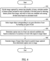
- a method implemented by a processor includes dividing an image captured by a camera into a plurality of areas, calculating a number of feature points included in each of the plurality of divided areas by detecting the feature points from the image, selecting at least one candidate area among the plurality of divided areas based on a result of the calculating, selecting a target object corresponding to an eye gaze direction of a user by tracking an eye gaze of the user, determining a capture area in the at least one selected candidate area based on detection of occurrence of an event with respect to the target object, and generating an image of the target object based on a partial image captured from the determined capture area in the image.
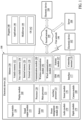
- the sound output module 155 may output a sound signal to the outside of the electronic device 101.
- the sound output module 155 may include, for example, a speaker or a receiver.
- the speaker may be used for general purposes, such as playing multimedia or playing record.
- the receiver may be used to receive an incoming call. According to an embodiment, the receiver may be implemented separately from the speaker or as a part of the speaker.
- the audio module 170 may convert a sound into an electric signal and vice versa. According to an embodiment, the audio module 170 may obtain the sound via the input module 150 or output the sound via the sound output module 155 or an external electronic device (e.g., an electronic device 102 such as a speaker or headphones) directly or wirelessly connected to the electronic device 101.
- an external electronic device e.g., an electronic device 102 such as a speaker or headphones
- the interface 177 may support one or more specified protocols to be used for the electronic device 101 to be coupled with the external electronic device (e.g., the electronic device 102) directly (e.g., by wire) or wirelessly.
- the interface 177 may include, for example, a high-definition multimedia interface (HDMI), a universal serial bus (USB) interface, a secure digital (SD) card interface, or an audio interface.
- HDMI high-definition multimedia interface
- USB universal serial bus
- SD secure digital
- the connecting terminal 178 may include a connector via which the electronic device 101 may be physically connected to an external electronic device (e.g., the electronic device 102).
- the connecting terminal 178 may include, for example, an HDMI connector, a USB connector, an SD card connector, or an audio connector (e.g., a headphone connector).
- the haptic module 179 may convert an electric signal into a mechanical stimulus (e.g., a vibration or a movement) or an electrical stimulus which may be recognized by a user via his or her tactile sensation or kinesthetic sensation.
- the haptic module 179 may include, for example, a motor, a piezoelectric element, or an electric stimulator.
- the camera module 180 may capture a still image and moving images. According to an embodiment, the camera module 180 may include one or more lenses, image sensors, ISPs, or flashes.
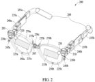
- FIG. 2 is a diagram illustrating a structure of an example wearable augmented reality (AR) device according to various embodiments.
- AR augmented reality
- At least one sensor e.g., a gyro sensor, an acceleration sensor, a geomagnetic sensor, a UWB sensor, a touch sensor, an illuminance sensor and/or a gesture sensor
- the first cameras 245a and 245b may perform at least one of the functions among head tracking for 6DoF, pose estimation and prediction, gesture and/or space recognition, and a SLAM function through depth imaging.
- a corresponding one (not shown) of these communication modules may communicate with the external electronic device via a short-range communication network (e.g., BluetoothTM, Wi-Fi direct, or IrDA) or a long-range communication network (e.g., a legacy cellular network, a 5G network, a next-generation communication network, the Internet, or a computer network (e.g., a LAN or a WAN).
- a short-range communication network e.g., BluetoothTM, Wi-Fi direct, or IrDA
- a long-range communication network e.g., a legacy cellular network, a 5G network, a next-generation communication network, the Internet, or a computer network (e.g., a LAN or a WAN).
- These various types of communication modules may be implemented as a single component (e.g., a single chip), or may be implemented as multi components (e.g., multi chips) separate from each other.
- the wearable AR device 200 may further include an antenna module (not shown).
- the antenna module may transmit or receive a signal or power to or from the outside (e.g., an external electronic device) of the wearable AR device 200.
- the antenna module may include an antenna including a radiating element including a conductive material or a conductive pattern formed in or on a substrate (e.g., the first PCB 23 5a and the second PCB 235b).
- the antenna module may include a plurality of antennas (e.g., array antennas).
- FIG. 4 is a flowchart illustrating an example operation of obtaining an image of a target object according to various embodiments.
- the electronic device may identify objects 721, 722, and 723 in an image 710.
- the object may be a real object or a virtual object.
- the object 721, the object 722, and the object 723 may represent a cup, a keyboard, and a monitor, respectively.
- FIGS. 8 and 9 are diagrams illustrating example detection of the occurrence of an event associated with a user's gesture according to various embodiments.
- the electronic device may determine a user's gesture detected before detecting the occurrence of the event, as a user's gesture associated with the target object. As described below, the electronic device may detect the occurrence of an event and determine a user's gesture detected after a capture area is determined, as a user's gesture associated with the capture area.
- the electronic device may divide an image 1010 into a plurality of areas and select candidate areas 1012-1, 1012-2, and 1012-3 from among the plurality of divided areas based on complexity.
- the electronic device may select a target object 1020 from the image 1010.
- the electronic device may determine a position and size of a capture area 1050 in the selected candidate areas 1012-1, 1012-2, and 1012-3.
- the electronic device may determine a capture area in the selected candidate areas 1012-1, 1012-2, and 1012-3 based on color information on the object area, in which the target object 1020 is displayed.
- the electronic device may calculate the color information on the object area, in which the target object 1020 is displayed, in the image 1010.
- the electronic device may calculate, as color information, an average color of pixels included in the object area, in which the target object 1020 is displayed, and calculate, as color information, a color histogram of pixels included in the object area, in which the target object 1020 is displayed.
- the color histogram herein may represent a distribution for each color.
- the electronic device may designate an arbitrary area having a predetermined size in the selected candidate areas 1012-1, 1012-2, and 1012-3.
- the electronic device may calculate color information on the designated area and compare it with the color information on the object area, in which the target object 1020 is displayed.
- the electronic device may give, to the designated area, a first score associated with the color information based on a comparison result.
- the electronic device may give a lower first score based on the color information on the designated area being similar to the color information on the object area, in which the target object 1020 is displayed, and may give a higher first score based on the color information on the designated area being not similar to the color information on the object area, in which the target object 1020 is displayed.
- the electronic device may determine, as the capture area, an area having the highest first score associated with the color information in the candidate areas 1012-1, 1012-2, and 1012-3 based on the color information on the object area, in which the target object 1020 is displayed.
- the electronic device may give a higher second score based on the designated area being closer to the user's preferred area, and may give a lower second score based on the designated area being further away from the user's preferred area.
- the electronic device may determine, as the capture area, an area having the highest second score in the candidate areas 1012-1, 1012-2, and 1012-3 based on the user's preferred area.
- the electronic device may determine a capture area in the selected candidate areas 1012-1, 1012-2, and 1012-3 further considering a probability value that the target object 1020 is classified as a corresponding object. For example, the electronic device may determine an object corresponding to the target object 1020 as a "wireless charging case". The electronic device may calculate a probability value that the target object 1020 is classified as the "wireless charging case". When the probability value that the target object 1020 is classified as the "wireless charging case" is greater than a threshold probability value, the electronic device may determine that it is easy to recognize the target object 1020 and may reduce an effect of a background of the image at the time of determining the capture area.
- the electronic device may redetect the feature points in the image after detecting the occurrence of an event. Based on detection of movement of a camera, the electronic device may recalculate the number of feature points included in each of the plurality of divided areas by redetecting the feature points in the image after detecting the occurrence of an event, and reselect at least one candidate area among the plurality of divided areas based on the recalculated result. For example, based on detection of a global motion in the image, the electronic device may redetect feature points in the image after detecting the occurrence of an event, recalculate the number of feature points included in each of the plurality of areas, and reselect a candidate area.
- the electronic device may determine a capture area 1150 in an image 1110.
- the electronic device may calculate the level of noise in the capture area 1150 of the image 1110.
- the noise may indicate a degree to which an area is difficult to be used as a capture area.
- the electronic device may determine that the area is not suitable to be used as the capture area, based on the noise being large, and may determine that the area is suitable to be used as the capture area, based on the noise being small.
- the electronic device may calculate the noise level in the capture area based on the number of feature points detected in the capture area, color information on the object area, in which the target object is displayed, and/or a probability value that the target object is classified as a corresponding object.
- the electronic device may display, on the display, at least one of a warning message or information guiding positional movement of the capture area.
- the electronic device may calculate the noise level in the capture area 1150 determined in the image 1110.
- the electronic device may determine that the capture area 1150 is at an unfavorable position for object registration.
- the electronic device may output, to the display, at least one of a warning message indicating that the capture area 1150 is unfavorable to the object registration or information guiding positional movement of the capture area 1150.
- the electronic device may change a position and size of a capture area.
- the electronic device may compare an object area, in which a target object is displayed, with a capture area.
- the electronic device may change at least one of a position or size of the capture area such that the capture area includes the object area, in which the target object is displayed.
- the electronic device may select a target object 1221 from an image 1210 and determine a capture area 1251.
- the electronic device may compare the object area, in which the target object 1221 is displayed, with the capture area 1251, and determine that the target object 1221 is out of the capture area 1251 when the capture area 1251 does not include at least a portion of the object area, in which the target object 1221 is displayed.
- the electronic device may change at least one of the position or size of the capture area 1251 such that the capture area 1251 includes the object area, in which the target object 1221 is displayed.
- FIG. 12 illustrates that the electronic device changes the capture area 1251 to a capture area 1252 to include the object area, in which the target object 1221 is displayed.
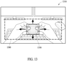
- FIG. 13 is a diagram illustrating an example positional change of a capture area according to various embodiments.
- the electronic device may change a position of a capture area.
- the electronic device may divide an image 1310 into a plurality of areas and select a candidate area among the plurality of divided areas.
- the electronic device may identify a boundary area 1380 which may be used as a capture area among the selected candidate areas.
- the electronic device may identify the boundary area 1380, which may be used as the capture area, among the candidate areas, based on at least one of color information on an object area, in which a target object is displayed, a user's preferred area in an image, feature points detected in the image, or a probability value that the target object is classified as a corresponding obj ect or a combination of two or more thereof.
- the electronic device may move the capture area in the boundary area 1380.
- the electronic device may display information on movable directions of the capture area 1350 around the capture area 1350.
- the electronic device may display interface objects in the form of arrows around the capture area 1350 based on the boundary area 1380 which may be used as the capture area, the arrows representing that the capture area 1350 may move upwards and downwards and to the right and left.
- FIG. 14 is a diagram illustrating an exmaple process of providing a rotation guide in a capture area according to various embodiments.
- An electronic device may provide a rotation guide for obtaining images of a plurality of cross sections of a target object in a capture area.
- the electronic device may display a graphic object for guiding the rotation of the target object on a display which outputs an image 1410.
- the electronic device may display, on the display, the images of the plurality of cross sections of the target object captured in the capture area.
- the electronic device may determine a capture area 1450 in the image 1410.
- the electronic device may detect that a target object 1420 enters the capture area 1450.
- the electronic device may display the graphic object for guiding the rotation of the target object 1420 on the display, in order to obtain images of the target object 1420.
- the electronic device may display graphic objects 1471 and 1472 instructing to rotate the target object 1420 in left and right directions, respectively.
- the electronic device may obtain the images of the cross sections of the target object 1420 for each image frame from the capture area 1450.
- the electronic device may further display, on the display, images 1481, 1482, and 1483 of the plurality of cross sections of the target object 1420 at various angles captured from the capture area 1450.
- the electronic device may display, on the display, graphic objects 1473 and 1474 instructing to rotate the target object 1420 in other directions (e.g., the upward and downward directions), respectively.
- the electronic device may end the obtaining of the images of the target object 1420 in the capture area 1450.
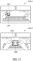
- FIG. 15 is a diagram illustrating an example process of determining a position and size of a capture area according to various embodiments.
- the electronic device may determine a position and size of a capture area based on a position and size of an object area, in which a target object is displayed. For example, the electronic device may determine the size of the capture area based on the size of the object area, in which the target object is displayed. The electronic device may also increase the size of the capture area when the size of the object area, in which the target object is displayed, in the image increases. For another example, the electronic device may determine the position of the capture area based on the position of the object area, in which the target object is displayed. For example, when the position of the object area, in which the target object is displayed, in the image is changed, the electronic device may also change the position of the capture area.
- the electronic device may track the object area, in which the target object is displayed, and may change at least one of the position or size of the capture area such that the capture area includes the tracked object area.
- the electronic device may determine a capture area 1551 based on an object area, in which a target object 1521 is displayed, in an image frame 1510-1, and determine a capture area 1552 based on an object area, in which a target object 1522 is displayed, in an image frame 1510-2 at a different time point.
- the electronic device may determine a shape of the capture area based on a shape of the object area, in which the target object is displayed. For example, when the shape of the object area, in which the target object is displayed, is a circle, the shape of the capture area may also be determined to be a circle.
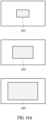
- FIGS. 16A and 16B are diagrams illustrating an example process of automatically determining a position and size of a capture area according to various embodiments.
- the electronic device may automatically determine the position and size of the capture area.
- the electronic device may automatically determine a capture area in an image to have a predetermined size at a predetermined position. For example, the electronic device may determine the capture area such that a center of the capture area coincides with a center of the image in the image. The electronic device may determine the capture area having a predetermined size while the center of the image coincides with the center of the capture area in the image.
- FIG. 16A illustrates a capture area 1651 having a first size, a capture area 1652 having a second size, or a capture area 1653 having a third size.
- the second size may be larger than the first size
- the third size may be larger than the second size.
- the electronic device may divide an image into a plurality of areas and may determine a size of a capture area based on a candidate area selected from among the plurality of divided areas.
- the electronic device may determine the size of the capture area based on a number of selected candidate areas and positions of the selected candidate areas in the image. For example, the electronic device may increase the size of the capture area based on the number of selected candidate areas being large, and may decrease the size of the capture area based on the number of adj acent candidate areas being small. As shown in FIG.
- the electronic device may determine a capture area 1654 having a fourth size in the selected candidate areas.
- the electronic device may determine a capture area 1655 having a fifth size in the selected candidate areas.
- the fifth size may be larger than the fourth size.
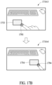
- FIGS. 17A and 17B are diagrams illustrating an example process of determining a position and size of a capture area based on a user's gesture according to various embodiments.
- the electronic device may determine a position and size of a capture area based on a user's gesture.
- the electronic device may change at least one of the position or size of the capture area based on the recognized user's gesture.
- FIG. 17B illustrates an example in which the electronic device changes a position of a capture area in an image based on a user's gesture.
- the electronic device may determine a capture area 1753 in an image frame 1710-3 at a time point C and recognize a hand gesture of a user's finger entering an area 1793 corresponding to one end point of the determined capture area 1753.
- the electronic device may change a position of a capture area such that an area 1794, where a user's finger is positioned, corresponds to one end point of a capture area 1754 in an image frame 1710-4 at a time point D.
- the electronic device may maintain the same size of the capture area.
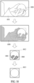
- FIG. 18 is a diagram illustrating an example process of generating an image of a target object based on a partial image captured from a capture area according to various embodiments.
- the electronic device may generate an image of a target object based on a partial image captured from a capture area determined from an image.
- a partial image captured from a capture area in one image frame constituting an image will be mainly described.
- the electronic device may obtain a partial image 1811 captured from a capture area in one image frame.
- the electronic device may identify a remaining area 1830 in the partial image 1811 except for an object area, in which a target object 1820 is displayed.
- the electronic device may obtain an image 1812 displaying only an object area, in which the target object 1820 is displayed, by removing the remaining area 1830 from the partial image 1811.
- the electronic device may identify areas 1841 and 1842, in which the target object 1820 is covered, in the image 1812.
- the electronic device may restore the areas 1841 and 1842, in which the target object 1820 is covered, by using the object area, in which the target object 1820 is displayed, and generate a final image 1813 of the target object 1821 according to the restoration of the areas 1841 and 1842, in which the target object 1820 is covered.
- the electronic device may improve image quality of the final image 1813 of the target object 1820.
- the electronic device may improve the image quality of the final image 1813 by at least one method of colorizing, noise reduction, upscaling, super-resolution, deblurring, low light, or a shadow.
- the electronic device may generate final images of the target object 1820 for each image frame included in the image.
- the electronic device may perform 3D modeling for the target object 1820 by combining the generated final images.
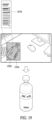
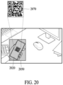
- FIGS. 19 and 20 are diagrams illustrating an example method of obtaining an image of a target object according to various embodiments.
- An electronic device may receive an image of a target obj ect from a database, instead of generating the image of the target obj ect based on a partial image captured from a capture area.
- the electronic device may establish communication with the database.
- FIG. 19 illustrates an example of recognizing a barcode in an object area, in which a target object is displayed.
- the electronic device may identify an object area, in which a target object 1920 is displayed, in a capture area 1950.
- the electronic device may recognize a barcode 1970 in the object area, in which the target object 1920 is displayed, and transmit the recognized barcode 1970 to the database.
- the database may pre-store images of objects matching each barcode.
- the electronic device may obtain an image of an object matching the barcode 1970 from the database.
- FIG. 20 illustrates a case of recognizing a quick response (QR) code in an object area, in which a target object is displayed.
- the electronic device may identify an object area, in which a target object 2020 is displayed, in a capture area 2050.
- the electronic device may recognize a QR code 2070 in the object area, in which the target object 2020 is displayed, and transmit the recognized QR code 2070 to the database.
- the database may pre-store information corresponding to the QR code.
- the electronic device may receive information matching the QR code 2070 from the database.
- An electronic device may include a camera, a memory configured to store computer-executable instructions, and a processor configured to execute the instructions by accessing the memory.
- the instructions may be configured to divide an image captured by the camera into a plurality of areas, calculate a number of feature points included in each of the plurality of divided areas by detecting the feature points from the image, select at least one candidate area among the plurality of divided areas based on a result of the calculating, select a target object corresponding to an eye gaze direction of a user by tracking an eye gaze of the user, determine a capture area in the at least one selected candidate area based on detection of occurrence of an event with respect to the target object, and generate an image of the target object based on a partial image captured from the determined capture area in the image.
- the instructions may be configured to detect the occurrence of the event based on detection of a gesture of the user associated with the target object from the image.
- the instructions may be further configured to determine the capture area in the at least one candidate area based on at least one or a combination of two or more of color information on an object area, in which the target object is displayed, a user's preferred area in the image, the feature points detected from the image, or a probability value that the target object is classified as a corresponding object.
- the instructions may be further configured to, based on detection of movement of the camera, recalculate the number of feature points included in each of the plurality of divided areas by redetecting the feature points from the image after the occurrence of the event is detected, and reselect the at least one candidate area among the plurality of divided areas based on the recalculated result.
- the instructions may be further configured to calculate a noise level in the capture area based on the number of feature points detected from the capture area, color information on an object area, in which the target object is displayed, and a probability value that the target object is classified as a corresponding object, and when the calculated noise level is greater than or equal to a threshold noise level, display, on a display, at least one of a warning message or information guiding positional movement of the capture area.
- the instructions may be further configured to compare an object area, in which the target object is displayed, with the capture area, and when the target object is out of the capture area based on the comparison result, change at least one of a position or size of the capture area such that the capture area includes the object area, in which the target object is displayed.
- the instructions may be further configured to, when the target object enters the capture area, display, on a display, a graphic object for guiding rotation of the target object, and when the rotation of the target object is detected, display, on the display, images of a plurality of cross sections of the target object captured in the capture area.
- the instructions may be further configured to, when movement of the target object is detected from the image, track an object area, in which the target object is displayed, and change at least one of a position or size of the capture area such that the capture area includes the tracked object area.
- the instructions may be further configured to, when a gesture of the user associated with the capture area is recognized, change at least one of a position or size of the capture area based on the recognized gesture of the user.
- a method implemented by a processor may include dividing an image captured by a camera into a plurality of areas, calculating a number of feature points included in each of the plurality of divided areas by detecting the feature points from the image, selecting at least one candidate area among the plurality of divided areas based on a result of the calculating, selecting a target object corresponding to an eye gaze direction of a user by tracking an eye gaze of the user, determining a capture area in the at least one selected candidate area based on detection of occurrence of an event with respect to the target object, and generating an image of the target object based on a partial image captured from the determined capture area in the image.
- the determining of the capture area may include detecting the gesture of the user associated with the target object entering an event detection area surrounding an object area, in which the target object is displayed, and detecting the occurrence of the event in response to the detected gesture of the user which has the same (or similar) form as one of pre-stored hand gestures.
- the method implemented by the processor may further include, based on detection of movement of the camera, recalculating the number of feature points included in each of the plurality of divided areas by redetecting the feature points from the image after the occurrence of the event is detected, and reselecting the at least one candidate area among the plurality of divided areas based on the recalculated result.
- the method implemented by the processor according to an embodiment may further include, when the target object enters the capture area, displaying, on a display, a graphic object for guiding rotation of the target object, and, when the rotation of the target object is detected, displaying, on the display, images of a plurality of cross sections of the target object captured in the capture area.
Landscapes
- Engineering & Computer Science (AREA)
- Multimedia (AREA)
- Signal Processing (AREA)
- Theoretical Computer Science (AREA)
- General Physics & Mathematics (AREA)
- Physics & Mathematics (AREA)
- Human Computer Interaction (AREA)
- Computer Vision & Pattern Recognition (AREA)
- General Engineering & Computer Science (AREA)
- Health & Medical Sciences (AREA)
- General Health & Medical Sciences (AREA)
- Psychiatry (AREA)
- Social Psychology (AREA)
- User Interface Of Digital Computer (AREA)
Applications Claiming Priority (3)
| Application Number | Priority Date | Filing Date | Title |
|---|---|---|---|
| KR20220018405 | 2022-02-11 | ||
| KR1020220029608A KR20230121516A (ko) | 2022-02-11 | 2022-03-08 | 객체의 영상을 획득하는 방법 및 장치 |
| PCT/KR2022/020173 WO2023153611A1 (fr) | 2022-02-11 | 2022-12-12 | Procédé et dispositif d'obtention d'image d'objet |
Publications (2)
| Publication Number | Publication Date |
|---|---|
| EP4398593A1 true EP4398593A1 (fr) | 2024-07-10 |
| EP4398593A4 EP4398593A4 (fr) | 2025-02-26 |
Family
ID=87558283
Family Applications (1)
| Application Number | Title | Priority Date | Filing Date |
|---|---|---|---|
| EP22926208.4A Pending EP4398593A4 (fr) | 2022-02-11 | 2022-12-12 | Procédé et dispositif d'obtention d'image d'objet |
Country Status (2)
| Country | Link |
|---|---|
| US (1) | US12348856B2 (fr) |
| EP (1) | EP4398593A4 (fr) |
Families Citing this family (1)
| Publication number | Priority date | Publication date | Assignee | Title |
|---|---|---|---|---|
| CN118567490B (zh) * | 2024-08-01 | 2024-11-29 | 浙江大学 | 一种基于低精度超宽带信号的手势识别方法和装置 |
Family Cites Families (29)
| Publication number | Priority date | Publication date | Assignee | Title |
|---|---|---|---|---|
| US6973212B2 (en) | 2000-09-01 | 2005-12-06 | Siemens Corporate Research, Inc. | Graph cuts for binary segmentation of n-dimensional images from object and background seeds |
| US8843857B2 (en) * | 2009-11-19 | 2014-09-23 | Microsoft Corporation | Distance scalable no touch computing |
| US9530232B2 (en) | 2012-09-04 | 2016-12-27 | Qualcomm Incorporated | Augmented reality surface segmentation |
| KR101360061B1 (ko) * | 2012-12-05 | 2014-02-12 | 현대자동차 주식회사 | 증강 현실 제공 방법 및 그 장치 |
| US20140191927A1 (en) * | 2013-01-09 | 2014-07-10 | Lg Electronics Inc. | Head mount display device providing eye gaze calibration and control method thereof |
| US9619021B2 (en) * | 2013-01-09 | 2017-04-11 | Lg Electronics Inc. | Head mounted display providing eye gaze calibration and control method thereof |
| KR20140090552A (ko) * | 2013-01-09 | 2014-07-17 | 엘지전자 주식회사 | 시선 캘리브레이션을 제공하는 헤드 마운트 디스플레이 및 그 제어 방법 |
| US10262462B2 (en) | 2014-04-18 | 2019-04-16 | Magic Leap, Inc. | Systems and methods for augmented and virtual reality |
| KR102083963B1 (ko) | 2013-12-10 | 2020-04-14 | 엘지전자 주식회사 | 시선 캘리브레이션을 제공하는 헤드 마운트 디스플레이 디바이스 및 그 제어 방법 |
| JP2015149552A (ja) | 2014-02-05 | 2015-08-20 | 株式会社ニコン | ウェアラブル型電子機器 |
| US10203762B2 (en) | 2014-03-11 | 2019-02-12 | Magic Leap, Inc. | Methods and systems for creating virtual and augmented reality |
| KR101687017B1 (ko) | 2014-06-25 | 2016-12-16 | 한국과학기술원 | 머리 착용형 컬러 깊이 카메라를 활용한 손 위치 추정 장치 및 방법, 이를 이용한 맨 손 상호작용 시스템 |
| US10719939B2 (en) | 2014-10-31 | 2020-07-21 | Fyusion, Inc. | Real-time mobile device capture and generation of AR/VR content |
| US10817065B1 (en) | 2015-10-06 | 2020-10-27 | Google Llc | Gesture recognition using multiple antenna |
| US10268266B2 (en) | 2016-06-29 | 2019-04-23 | Microsoft Technology Licensing, Llc | Selection of objects in three-dimensional space |
| DK179471B1 (en) | 2016-09-23 | 2018-11-26 | Apple Inc. | IMAGE DATA FOR ENHANCED USER INTERACTIONS |
| KR102391490B1 (ko) | 2017-03-27 | 2022-04-28 | 삼성전자주식회사 | 이미지 내의 오브젝트를 트래킹하기 위한 방법 및 그 전자 장치 |
| CN107247511B (zh) | 2017-05-05 | 2019-07-16 | 浙江大学 | 一种基于虚拟现实中眼动捕捉的跨物体交互方法与装置 |
| IL293424A (en) | 2017-07-26 | 2022-07-01 | Magic Leap Inc | Neural network training with displays of user interface devices |
| CN114924651A (zh) | 2017-09-29 | 2022-08-19 | 苹果公司 | 基于注视的用户交互 |
| CN108897589B (zh) * | 2018-05-31 | 2020-10-27 | 刘国华 | 显示设备中人机交互方法、装置、计算机设备和存储介质 |
| EP3814829A4 (fr) | 2018-06-27 | 2022-03-23 | Sentiar, Inc. | Interface basée sur le regard pour environnement de réalité augmentée |
| CN111479104A (zh) * | 2018-12-21 | 2020-07-31 | 托比股份公司 | 用于计算视线会聚距离的方法 |
| JP7425562B2 (ja) * | 2019-08-14 | 2024-01-31 | キヤノン株式会社 | 撮像装置およびその制御方法 |
| SG10201913029SA (en) * | 2019-12-23 | 2021-04-29 | Sensetime Int Pte Ltd | Target tracking method and apparatus, electronic device, and storage medium |
| KR102312601B1 (ko) | 2020-04-01 | 2021-10-15 | 삼성전자주식회사 | 시선 추적을 이용한 시인성 개선 방법, 저장 매체 및 전자 장치 |
| GB2595461B (en) * | 2020-05-26 | 2023-06-07 | Sony Interactive Entertainment Inc | Gaze tracking apparatus and systems |
| JP2023087355A (ja) * | 2021-12-13 | 2023-06-23 | キヤノン株式会社 | 電子機器 |
| KR102824650B1 (ko) * | 2021-12-27 | 2025-06-24 | 삼성전자주식회사 | 객체 추적 방법 및 장치 |
-
2022
- 2022-12-12 EP EP22926208.4A patent/EP4398593A4/fr active Pending
-
2023
- 2023-01-30 US US18/102,956 patent/US12348856B2/en active Active
Also Published As
| Publication number | Publication date |
|---|---|
| US20230262323A1 (en) | 2023-08-17 |
| EP4398593A4 (fr) | 2025-02-26 |
| US12348856B2 (en) | 2025-07-01 |
Similar Documents
| Publication | Publication Date | Title |
|---|---|---|
| US12462443B2 (en) | Electronic device for placing object according to space in augmented reality and operation method of electronic device | |
| US11733952B2 (en) | Wearable electronic device including display, method for controlling display, and system including wearable electronic device and case | |
| US11928257B2 (en) | Method and electronic device for tracking eye | |
| US20220329726A1 (en) | Wearable electronic device including cameras | |
| US20230122744A1 (en) | Wearable electronic device adjusting transmittance of visor and brightness of display | |
| US20250384598A1 (en) | Electronic device and method for anchoring of augmented reality object | |
| US20230199328A1 (en) | Method of removing interference and electronic device performing the method | |
| US20250069535A1 (en) | Method and device for controlling luminance of augmented reality (ar) image | |
| US12033382B2 (en) | Electronic device and method for representing contents based on gaze dwell time | |
| EP4403980A1 (fr) | Dispositif électronique habitronique comprenant une terre variable | |
| EP4398593A1 (fr) | Procédé et dispositif d'obtention d'image d'objet | |
| US20250225742A1 (en) | Method for providing information based on gaze point and electronic device therefor | |
| US12542872B2 (en) | Electronic device for supporting various communications during video call, and operating method therefor | |
| EP4350420A1 (fr) | Ensemble lentille comprenant un élément électroluminescent disposé sur une première lentille, et dispositif électronique habitronique le comprenant | |
| US20230195223A1 (en) | Apparatus and method of controlling light source in eye tracking using glint | |
| US11741862B2 (en) | Augmented reality wearable electronic device including camera | |
| US12354225B2 (en) | Method and electronic device for displaying augmented reality content based on ambient illuminance | |
| US20260101115A1 (en) | Apparatus and method for controlling light sources for eye tracking | |
| US12455954B2 (en) | Apparatus and method for authenticating user in augmented reality | |
| US20250216683A1 (en) | Wearable device for guiding user's posture and method thereof | |
| US20260036818A1 (en) | Ar device and method for preventing glare in ar service image | |
| CN118679749A (zh) | 用于获得对象的图像的方法及设备 | |
| KR20230121516A (ko) | 객체의 영상을 획득하는 방법 및 장치 | |
| US20260099202A1 (en) | Electronic device and method for adjusting order of data sets for controlling led, and computer-readable storage medium | |
| EP4495749A1 (fr) | Procédé de commande de module d'affichage et dispositif électronique exécutant le procédé |
Legal Events
| Date | Code | Title | Description |
|---|---|---|---|
| STAA | Information on the status of an ep patent application or granted ep patent |
Free format text: STATUS: THE INTERNATIONAL PUBLICATION HAS BEEN MADE |
|
| PUAI | Public reference made under article 153(3) epc to a published international application that has entered the european phase |
Free format text: ORIGINAL CODE: 0009012 |
|
| STAA | Information on the status of an ep patent application or granted ep patent |
Free format text: STATUS: REQUEST FOR EXAMINATION WAS MADE |
|
| 17P | Request for examination filed |
Effective date: 20240404 |
|
| AK | Designated contracting states |
Kind code of ref document: A1 Designated state(s): AL AT BE BG CH CY CZ DE DK EE ES FI FR GB GR HR HU IE IS IT LI LT LU LV MC ME MK MT NL NO PL PT RO RS SE SI SK SM TR |
|
| A4 | Supplementary search report drawn up and despatched |
Effective date: 20250124 |
|
| RIC1 | Information provided on ipc code assigned before grant |
Ipc: G06V 10/25 20220101ALI20250120BHEP Ipc: H04N 23/80 20230101ALI20250120BHEP Ipc: H04N 23/611 20230101ALI20250120BHEP Ipc: H04N 5/262 20060101ALI20250120BHEP Ipc: H04N 23/63 20230101ALI20250120BHEP Ipc: H04N 23/62 20230101ALI20250120BHEP Ipc: G06F 3/01 20060101ALI20250120BHEP Ipc: G06T 7/292 20170101ALI20250120BHEP Ipc: G06T 5/00 20240101ALI20250120BHEP Ipc: G06T 7/246 20170101ALI20250120BHEP Ipc: G06T 7/11 20170101ALI20250120BHEP Ipc: H04N 23/60 20230101AFI20250120BHEP |
|
| DAV | Request for validation of the european patent (deleted) | ||
| DAX | Request for extension of the european patent (deleted) |