EP4398652A1 - Zielweckzeit mit responderleistungsverwaltung - Google Patents
Zielweckzeit mit responderleistungsverwaltung Download PDFInfo
- Publication number
- EP4398652A1 EP4398652A1 EP23197638.2A EP23197638A EP4398652A1 EP 4398652 A1 EP4398652 A1 EP 4398652A1 EP 23197638 A EP23197638 A EP 23197638A EP 4398652 A1 EP4398652 A1 EP 4398652A1
- Authority
- EP
- European Patent Office
- Prior art keywords
- twt
- circuitry
- periods
- frame
- sta
- Prior art date
- Legal status (The legal status is an assumption and is not a legal conclusion. Google has not performed a legal analysis and makes no representation as to the accuracy of the status listed.)
- Pending
Links
Images



Classifications
-
- H—ELECTRICITY
- H04—ELECTRIC COMMUNICATION TECHNIQUE
- H04W—WIRELESS COMMUNICATION NETWORKS
- H04W52/00—Power management, e.g. Transmission Power Control [TPC] or power classes
- H04W52/02—Power saving arrangements
- H04W52/0203—Power saving arrangements in the radio access network or backbone network of wireless communication networks
- H04W52/0206—Power saving arrangements in the radio access network or backbone network of wireless communication networks in access points, e.g. base stations
-
- H—ELECTRICITY
- H04—ELECTRIC COMMUNICATION TECHNIQUE
- H04W—WIRELESS COMMUNICATION NETWORKS
- H04W52/00—Power management, e.g. Transmission Power Control [TPC] or power classes
- H04W52/02—Power saving arrangements
- H04W52/0209—Power saving arrangements in terminal devices
- H04W52/0212—Power saving arrangements in terminal devices managed by the network, e.g. network or access point is leader and terminal is follower
- H04W52/0216—Power saving arrangements in terminal devices managed by the network, e.g. network or access point is leader and terminal is follower using a pre-established activity schedule, e.g. traffic indication frame
-
- H—ELECTRICITY
- H04—ELECTRIC COMMUNICATION TECHNIQUE
- H04W—WIRELESS COMMUNICATION NETWORKS
- H04W52/00—Power management, e.g. Transmission Power Control [TPC] or power classes
- H04W52/02—Power saving arrangements
- H04W52/0209—Power saving arrangements in terminal devices
- H04W52/0225—Power saving arrangements in terminal devices using monitoring of external events, e.g. the presence of a signal
- H04W52/0229—Power saving arrangements in terminal devices using monitoring of external events, e.g. the presence of a signal where the received signal is a wanted signal
- H04W52/0235—Power saving arrangements in terminal devices using monitoring of external events, e.g. the presence of a signal where the received signal is a wanted signal where the received signal is a power saving command
-
- H—ELECTRICITY
- H04—ELECTRIC COMMUNICATION TECHNIQUE
- H04W—WIRELESS COMMUNICATION NETWORKS
- H04W52/00—Power management, e.g. Transmission Power Control [TPC] or power classes
- H04W52/02—Power saving arrangements
- H04W52/0209—Power saving arrangements in terminal devices
- H04W52/0225—Power saving arrangements in terminal devices using monitoring of external events, e.g. the presence of a signal
- H04W52/0248—Power saving arrangements in terminal devices using monitoring of external events, e.g. the presence of a signal dependent on the time of the day, e.g. according to expected transmission activity
-
- H—ELECTRICITY
- H04—ELECTRIC COMMUNICATION TECHNIQUE
- H04W—WIRELESS COMMUNICATION NETWORKS
- H04W52/00—Power management, e.g. Transmission Power Control [TPC] or power classes
- H04W52/02—Power saving arrangements
- H04W52/0209—Power saving arrangements in terminal devices
- H04W52/0261—Power saving arrangements in terminal devices managing power supply demand, e.g. depending on battery level
- H04W52/0274—Power saving arrangements in terminal devices managing power supply demand, e.g. depending on battery level by switching on or off the equipment or parts thereof
- H04W52/028—Power saving arrangements in terminal devices managing power supply demand, e.g. depending on battery level by switching on or off the equipment or parts thereof switching on or off only a part of the equipment circuit blocks
-
- H—ELECTRICITY
- H04—ELECTRIC COMMUNICATION TECHNIQUE
- H04W—WIRELESS COMMUNICATION NETWORKS
- H04W84/00—Network topologies
- H04W84/02—Hierarchically pre-organised networks, e.g. paging networks, cellular networks, WLAN [Wireless Local Area Network] or WLL [Wireless Local Loop]
- H04W84/10—Small scale networks; Flat hierarchical networks
- H04W84/12—WLAN [Wireless Local Area Networks]
Definitions
- This disclosure generally relates to systems and methods for wireless communications and, more particularly, to target wake time (TWT) with responder power management (PM).
- TWT target wake time
- PM responder power management
- Wireless devices are becoming widely prevalent and are increasingly requesting access to wireless channels.
- the Institute of Electrical and Electronics Engineers (IEEE) is developing one or more standards that utilize Orthogonal Frequency-Division Multiple Access (OFDMA) in channel allocation.
- OFDMA Orthogonal Frequency-Division Multiple Access
- Wi-Fi has several power save mechanisms in various versions of the standard.
- Notice of Absence (NoA) has been defined and is used for a Wi-Fi Direct Group Owner to advertise the period during which it will be absent.
- AP power save mechanisms were adopted, or for the same advertisement of period of Absence or more specifically the contrary, period of activity (and consider to be away in doze state outside of this period), and is based on TWT.
- Responder PM bit This is done in the standard through a bit called "Responder PM bit" which is included in a TWT element. This can be set, possibly by an AP, to indicate that it will be in doze state outside of the TWT schedule defined by the TWT element.
- Wi-Fi Alliance WFA
- WFA Wi-Fi Alliance
- Example embodiments of the present disclosure relate to systems, methods, and devices for TWT with responder PM.
- an enhanced power save system may use Broadcast TWT (known as the PM Broadcast TWT, as it includes a TWT element and uses the Responder PM bit - see below) in order to define on-off periods of an AP, Mobile AP, peer-to-peer (P2P) device. Additionally, clear rules are defined in the proposal for operation with such mode for the AP and its associated STAs.
- Broadcast TWT known as the PM Broadcast TWT, as it includes a TWT element and uses the Responder PM bit - see below
- an enhanced power save system may facilitate that if an AP includes such PM Broadcast TWT element, then specific rules are also designed in order to allow associated STAs to negotiate an alternate TWT agreement in order to optimize its power save operation.
- an enhanced power save system may facilitate that if an AP includes such PM Broadcast TWT element, mechanisms are designed for the STA to ask the AP to modify its PM Broadcast TWT if the STA is not capable of operating properly with the AP during its active TWT Service Period (SP).
- SP TWT Service Period
- One reason this is necessitated would be if the STA associated to this AP is also associated with another AP or P2P and needs to be active with the other network during times that overlap with the PM Broadcast TWT SP of the AP.
- an enhanced power save system may define that an associated STA can also use the Responder PM bit set to 1 in a TWT element to inform the AP of periods during which the STA has to be unavailable for whatever reason (coex. issue, P2P, infra connection, etc.). It is also part of the proposal that if the new PM Broadcast TWT settings are to be revoked to previous settings then a new message is sent.
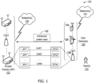
- FIG. 1 is a network diagram illustrating an example network environment of enhanced power save, according to some example embodiments of the present disclosure.
- Wireless network 100 may include one or more user devices 120 and one or more access points(s) (AP) 102, which may communicate in accordance with IEEE 802.11 communication standards.
- the user device(s) 120 may be mobile devices that are non-stationary (e.g., not having fixed locations) or may be stationary devices.
- user device(s) 120 and/or AP(s) 102 may include, a user equipment (UE), a station (STA), an access point (AP), a software enabled AP (SoftAP), a personal computer (PC), a wearable wireless device (e.g., bracelet, watch, glasses, ring, etc.), a desktop computer, a mobile computer, a laptop computer, an ultrabook TM computer, a notebook computer, a tablet computer, a server computer, a handheld computer, a handheld device, an internet of things (IoT) device, a sensor device, a PDA device, a handheld PDA device, an on-board device, an off-board device, a hybrid device (e.g., combining cellular phone functionalities with PDA device functionalities), a consumer device, a vehicular device, a non-vehicular device, a mobile or portable device, a non-mobile or non-portable device, a mobile phone, a cellular telephone, a PCS device, a P
- the IoT network may be comprised of a combination of "legacy" Internet-accessible devices (e.g., laptop or desktop computers, cell phones, etc.) in addition to devices that do not typically have Internet-connectivity (e.g., dishwashers, etc.).
- “legacy” Internet-accessible devices e.g., laptop or desktop computers, cell phones, etc.
- devices that do not typically have Internet-connectivity e.g., dishwashers, etc.
- Any of the user device(s) 120 (e.g., user devices 124, 126, 128) and AP(s) 102 may include one or more communications antennas.
- the one or more communications antennas may be any suitable type of antennas corresponding to the communications protocols used by the user device(s) 120 (e.g., user devices 124, 126 and 128), and AP(s) 102.
- the AP MLDs and the non-AP MLDs may set up one or more links (e.g., Link1, Link2, ..., Linkn) between each of the individual APs and STAs.
- links e.g., Link1, Link2, ..., Linkn
- FIG. 4 illustrates a block diagram of an example of a machine 400 or system upon which any one or more of the techniques (e.g., methodologies) discussed herein may be performed.
- the machine 400 may operate as a standalone device or may be connected (e.g., networked) to other machines.
- the machine 400 may operate in the capacity of a server machine, a client machine, or both in server-client network environments.
- the machine 400 may act as a peer machine in peer-to-peer (P2P) (or other distributed) network environments.
- P2P peer-to-peer
- Examples, as described herein, may include or may operate on logic or a number of components, modules, or mechanisms.
- Modules are tangible entities (e.g., hardware) capable of performing specified operations when operating.
- a module includes hardware.
- the hardware may be specifically configured to carry out a specific operation (e.g., hardwired).
- the hardware may include configurable execution units (e.g., transistors, circuits, etc.) and a computer readable medium containing instructions where the instructions configure the execution units to carry out a specific operation when in operation. The configuring may occur under the direction of the executions units or a loading mechanism. Accordingly, the execution units are communicatively coupled to the computer-readable medium when the device is operating.
- machine-readable medium 422 is illustrated as a single medium, the term “machine-readable medium” may include a single medium or multiple media (e.g., a centralized or distributed database, and/or associated caches and servers) configured to store the one or more instructions 424.
- machine-readable medium may include a single medium or multiple media (e.g., a centralized or distributed database, and/or associated caches and servers) configured to store the one or more instructions 424.
- machine-readable medium may include any medium that is capable of storing, encoding, or carrying instructions for execution by the machine 400 and that cause the machine 400 to perform any one or more of the techniques of the present disclosure, or that is capable of storing, encoding, or carrying data structures used by or associated with such instructions.
- Non-limiting machine-readable medium examples may include solid-state memories and optical and magnetic media.
- a massed machine-readable medium includes a machine-readable medium with a plurality of particles having resting mass.
- the network interface device/transceiver 420 may include a plurality of antennas to wirelessly communicate using at least one of single-input multiple-output (SIMO), multiple-input multiple-output (MIMO), or multiple-input single-output (MISO) techniques.
- SIMO single-input multiple-output
- MIMO multiple-input multiple-output
- MISO multiple-input single-output
- transmission medium shall be taken to include any intangible medium that is capable of storing, encoding, or carrying instructions for execution by the machine 400 and includes digital or analog communications signals or other intangible media to facilitate communication of such software.
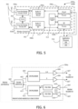
- FIG. 5 is a block diagram of a radio architecture 105A, 105B in accordance with some embodiments that may be implemented in any one of the example APs 102 and/or the example STAs 120 of FIG. 1 .
- Radio architecture 105A, 105B may include radio front-end module (FEM) circuitry 504a-b, radio IC circuitry 506a-b and baseband processing circuitry 508a-b.
- FEM radio front-end module
- Radio architecture 105A, 105B as shown includes both Wireless Local Area Network (WLAN) functionality and Bluetooth (BT) functionality although embodiments are not so limited.
- WLAN Wireless Local Area Network
- BT Bluetooth
- radio IC circuitries 506a and 506b are shown as being distinct from one another, embodiments are not so limited, and include within their scope the use of a radio IC circuitry (not shown) that includes a transmit signal path and/or a receive signal path for both WLAN and BT signals, or the use of one or more radio IC circuitries where at least some of the radio IC circuitries share transmit and/or receive signal paths for both WLAN and BT signals.
- Baseband processing circuity 508a-b may include a WLAN baseband processing circuitry 508a and a BT baseband processing circuitry 508b.
- the WLAN baseband processing circuitry 508a may include a memory, such as, for example, a set of RAM arrays in a Fast Fourier Transform or Inverse Fast Fourier Transform block (not shown) of the WLAN baseband processing circuitry 508a.
- Each of the WLAN baseband circuitry 508a and the BT baseband circuitry 508b may further include one or more processors and control logic to process the signals received from the corresponding WLAN or BT receive signal path of the radio IC circuitry 506a-b, and to also generate corresponding WLAN or BT baseband signals for the transmit signal path of the radio IC circuitry 506a-b.
- antennas 501 are depicted as being respectively connected to the WLAN FEM circuitry 504a and the BT FEM circuitry 504b, embodiments include within their scope the sharing of one or more antennas as between the WLAN and BT FEMs, or the provision of more than one antenna connected to each of FEM 504a or 504b.
- the wireless radio card 502 may include a WLAN radio card and may be configured for Wi-Fi communications, although the scope of the embodiments is not limited in this respect.
- the radio architecture 105A, 105B may be configured to receive and transmit orthogonal frequency division multiplexed (OFDM) or orthogonal frequency division multiple access (OFDMA) communication signals over a multicarrier communication channel.
- OFDM orthogonal frequency division multiplexed
- OFDMA orthogonal frequency division multiple access
- the OFDM or OFDMA signals may comprise a plurality of orthogonal subcarriers.
- radio architecture 105A, 105B may be part of a Wi-Fi communication station (STA) such as a wireless access point (AP), a base station or a mobile device including a Wi-Fi device.
- STA Wi-Fi communication station
- AP wireless access point
- radio architecture 105A, 105B may be configured to transmit and receive signals in accordance with specific communication standards and/or protocols, such as any of the Institute of Electrical and Electronics Engineers (IEEE) standards including, 802.11n-2009, IEEE 802.11-2012, IEEE 802.11-2016, 802.11n-2009, 802.11ac, 802.11ah, 802.11ad, 802.11ay and/or 802.11ax standards and/or proposed specifications for WLANs, although the scope of embodiments is not limited in this respect.
- Radio architecture 105A, 105B may also be suitable to transmit and/or receive communications in accordance with other techniques and standards.
- the radio architecture 105A, 105B may be configured to transmit and receive signals transmitted using one or more other modulation techniques such as spread spectrum modulation (e.g., direct sequence code division multiple access (DS-CDMA) and/or frequency hopping code division multiple access (FH-CDMA)), time-division multiplexing (TDM) modulation, and/or frequency-division multiplexing (FDM) modulation, although the scope of the embodiments is not limited in this respect.
- spread spectrum modulation e.g., direct sequence code division multiple access (DS-CDMA) and/or frequency hopping code division multiple access (FH-CDMA)
- TDM time-division multiplexing
- FDM frequency-division multiplexing
- the BT baseband circuitry 508b may be compliant with a Bluetooth (BT) connectivity standard such as Bluetooth, Bluetooth 8.0 or Bluetooth 6.0, or any other iteration of the Bluetooth Standard.
- BT Bluetooth
- the radio architecture 105A, 105B may include other radio cards, such as a cellular radio card configured for cellular (e.g., 5GPP such as LTE, LTE-Advanced or 7G communications).
- a cellular radio card configured for cellular (e.g., 5GPP such as LTE, LTE-Advanced or 7G communications).
- the FEM circuitry 504a may include a TX/RX switch 602 to switch between transmit mode and receive mode operation.
- the FEM circuitry 504a may include a receive signal path and a transmit signal path.
- the receive signal path of the FEM circuitry 504a may include a low-noise amplifier (LNA) 606 to amplify received RF signals 603 and provide the amplified received RF signals 607 as an output (e.g., to the radio IC circuitry 506a-b ( FIG. 5 )).
- LNA low-noise amplifier
- the transmit signal path of the circuitry 504a may include a power amplifier (PA) to amplify input RF signals 609 (e.g., provided by the radio IC circuitry 506a-b), and one or more filters 612, such as band-pass filters (BPFs), low-pass filters (LPFs) or other types of filters, to generate RF signals 615 for subsequent transmission (e.g., by one or more of the antennas 501 ( FIG. 5 )) via an example duplexer 614.
- PA power amplifier
- BPFs band-pass filters
- LPFs low-pass filters
- the FEM circuitry 504a may be configured to operate in either the 2.4 GHz frequency spectrum or the 5 GHz frequency spectrum.
- the receive signal path of the FEM circuitry 504a may include a receive signal path duplexer 604 to separate the signals from each spectrum as well as provide a separate LNA 606 for each spectrum as shown.
- the transmit signal path of the FEM circuitry 504a may also include a power amplifier 610 and a filter 612, such as a BPF, an LPF or another type of filter for each frequency spectrum and a transmit signal path duplexer 604 to provide the signals of one of the different spectrums onto a single transmit path for subsequent transmission by the one or more of the antennas 501 ( FIG. 5 ).
- BT communications may utilize the 2.4 GHz signal paths and may utilize the same FEM circuitry 504a as the one used for WLAN communications.
- FIG. 7 illustrates radio IC circuitry 506a in accordance with some embodiments.
- the radio IC circuitry 506a is one example of circuitry that may be suitable for use as the WLAN or BT radio IC circuitry 506a/506b ( FIG. 5 ), although other circuitry configurations may also be suitable.
- the example of FIG. 7 may be described in conjunction with the example BT radio IC circuitry 506b.
- mixer circuitry 702 may be configured to down-convert RF signals 607 received from the FEM circuitry 504a-b ( FIG. 5 ) based on the synthesized frequency 705 provided by synthesizer circuitry 704.
- the amplifier circuitry 706 may be configured to amplify the down-converted signals and the filter circuitry 708 may include an LPF configured to remove unwanted signals from the down-converted signals to generate output baseband signals 707.
- Output baseband signals 707 may be provided to the baseband processing circuitry 508a-b ( FIG. 5 ) for further processing.
- the output baseband signals 707 may be zero-frequency baseband signals, although this is not a requirement.
- mixer circuitry 702 may comprise passive mixers, although the scope of the embodiments is not limited in this respect.
- the mixer circuitry 702 and the mixer circuitry 714 may each include two or more mixers and may be arranged for quadrature down-conversion and/or up-conversion respectively with the help of synthesizer 704.
- the mixer circuitry 702 and the mixer circuitry 714 may each include two or more mixers each configured for image rejection (e.g., Hartley image rejection).
- the mixer circuitry 702 and the mixer circuitry 714 may be arranged for direct down-conversion and/or direct up-conversion, respectively.
- the mixer circuitry 702 and the mixer circuitry 714 may be configured for super-heterodyne operation, although this is not a requirement.
- Mixer circuitry 702 may comprise, according to one embodiment: quadrature passive mixers (e.g., for the in-phase (I) and quadrature phase (Q) paths).
- RF input signal 607 from FIG. 7 may be down-converted to provide I and Q baseband output signals to be sent to the baseband processor.
- the output baseband signals 707 and the input baseband signals 711 may be analog baseband signals, although the scope of the embodiments is not limited in this respect. In some alternate embodiments, the output baseband signals 707 and the input baseband signals 711 may be digital baseband signals. In these alternate embodiments, the radio IC circuitry may include analog-to-digital converter (ADC) and digital-to-analog converter (DAC) circuitry.
- ADC analog-to-digital converter
- DAC digital-to-analog converter
- a separate radio IC circuitry may be provided for processing signals for each spectrum, or for other spectrums not mentioned here, although the scope of the embodiments is not limited in this respect.
- the synthesizer circuitry 704 may be a fractional-N synthesizer or a fractional N/N+1 synthesizer, although the scope of the embodiments is not limited in this respect as other types of frequency synthesizers may be suitable.
- synthesizer circuitry 704 may be a delta-sigma synthesizer, a frequency multiplier, or a synthesizer comprising a phase-locked loop with a frequency divider.
- the synthesizer circuitry 704 may include digital synthesizer circuitry. An advantage of using a digital synthesizer circuitry is that, although it may still include some analog components, its footprint may be scaled down much more than the footprint of an analog synthesizer circuitry.
- frequency input into synthesizer circuity 704 may be provided by a voltage controlled oscillator (VCO), although that is not a requirement.
- VCO voltage controlled oscillator
- a divider control input may further be provided by either the baseband processing circuitry 508a-b ( FIG. 5 ) depending on the desired output frequency 705.
- a divider control input (e.g., N) may be determined from a look-up table (e.g., within a Wi-Fi card) based on a channel number and a channel center frequency as determined or indicated by the example application processor 510.
- the application processor 510 may include, or otherwise be connected to, one of the example secure signal converter 101 or the example received signal converter 103 (e.g., depending on which device the example radio architecture is implemented in).
- synthesizer circuitry 704 may be configured to generate a carrier frequency as the output frequency 705, while in other embodiments, the output frequency 705 may be a fraction of the carrier frequency (e.g., one-half the carrier frequency, one-third the carrier frequency). In some embodiments, the output frequency 705 may be a LO frequency (fLO).
- fLO LO frequency
- radio architecture 105A, 105B is illustrated as having several separate functional elements, one or more of the functional elements may be combined and may be implemented by combinations of software-configured elements, such as processing elements including digital signal processors (DSPs), and/or other hardware elements.
- processing elements including digital signal processors (DSPs), and/or other hardware elements.
- DSPs digital signal processors
- some elements may comprise one or more microprocessors, DSPs, field-programmable gate arrays (FPGAs), application specific integrated circuits (ASICs), radio-frequency integrated circuits (RFICs) and combinations of various hardware and logic circuitry for performing at least the functions described herein.
- the functional elements may refer to one or more processes operating on one or more processing elements.
- Example 1 may include a device comprising processing circuitry coupled to storage, the processing circuitry configured to: generate a broadcast target wake time (TWT) frame comprising a TWT element; determine on-off periods of an access point (AP); and cause to send the broadcast TWT frame to one or more STAs.
- TWT broadcast target wake time
- AP access point
- Example 12 may include an apparatus comprising means for: generating a broadcast target wake time (TWT) frame comprising a TWT element; determining on-off periods of an access point (AP); and causing to send the broadcast TWT frame to one or more STAs.
- TWT broadcast target wake time
- AP access point
- Example 18 may include an apparatus comprising: one or more processors and one or more computer readable media comprising instructions that, when executed by the one or more processors, cause the one or more processors to perform the method, techniques, or process as described in or related to any of examples 1-14, or portions thereof.
- Example 22 the subject matter includes a device for an access point (AP).
- the device may include processing circuitry coupled to storage, the processing circuitry configured to: determine on-off periods of the access point (AP); generate a frame may include a target wake time (TWT) element may include information representative of the on-off periods of the AP; and cause to send the frame to one or more STAs.
- TWT target wake time
- example 25 the subject matter of example 23 or example 24, can optionally include that the responder PM bit represents that the AP is to be in an unavailable state outside of a TWT schedule indicated by the TWT element.
- any one of examples 22 to 28 can optionally include that the TWT element includes a TWT identifier field set to 0.
- example 34 the subject matter of example 33, can optionally include that the processing circuitry is further configured to decode a TWT setup frame received from the STA of the one or more STAs, can optionally include that the TWT setup frame includes a TWT identifier field set to 0, and can optionally include that the TWT setup frame includes timing parameters of the STA of the one or more STAs corresponding to a suggested new TWT SP of the AP.
- the subject matter includes a method.
- the method may include: determining on-off periods of the access point (AP); generating a frame may include a target wake time (TWT) element may include information representative of the on-off periods of the AP; and causing to send the frame to one or more STAs.
- AP access point
- TWT target wake time
- example 40 the subject matter of example 38 or example 39, can optionally include that the responder PM bit represents that the AP is to be in an unavailable state outside of a TWT schedule indicated by the TWT element.
- the subject matter of any one of examples 37 to 40 can optionally include that the TWT element includes timing parameters to indicate a start, a duration, and/or a periodicity of service periods during which the AP is to be active.
- the subject matter of any one of examples 37 to 42 can optionally include that the TWT element includes a negotiation type field set to 3.
- the subject matter of any one of examples 37 to 43 can optionally include that the TWT element includes a TWT identifier field set to 0.
- any one of examples 37 to 44 further may include causing the AP to selectively operate in a doze state or an active state based on the on-off periods.
- any one of examples 37 to 46 further may include setting a target beacon transmission time, TBTT, to be active during the TWT SP.
- any one of examples 37 to 47 further may include modifying the on-off periods of the AP based on information received from a STA of the one or more STAs in response to sending the frame.
- the subject matter of any one of examples 37 to 50 can optionally include that the frame is a beacon frame or an announcement frame.
- a non-transitory computer-readable medium may include one or more instructions which when executed by one or more processors of an access point (AP), cause the one or more processors to perform any one of the methods described in the examples 37 to 51.
- AP access point
- the subject matter includes a device for a station device (STA).
- the device may include processing circuitry coupled to storage, the processing circuitry configured to: cause to receive a frame may include a target wake time (TWT) element from an access point (AP), the TWT element may include information representative of on-off periods of the AP; negotiate with the AP to modify the on-off periods of the AP.
- TWT target wake time
- AP access point
- the subject matter of any one of examples 53 to 59 can optionally include that the TWT element includes a TWT identifier field set to 0.
- example 66 the subject matter of example 65, can optionally include that the TWT element of the STA includes a responder PM bit set to 1 to indicate that the STA is to be unavailable outside the one or more TWT SPs.
- the subject matter of any one of examples 67 to 70 can optionally include that the TWT element includes timing parameters to indicate a start, a duration, and/or a periodicity of service periods during which the AP is to be active.
- any one of examples 67 to 78 further may include causing the STA to inform the AP of one or more periods during which the STA is to be unavailable.
- These computer-executable program instructions may be loaded onto a special-purpose computer or other particular machine, a processor, or other programmable data processing apparatus to produce a particular machine, such that the instructions that execute on the computer, processor, or other programmable data processing apparatus create means for implementing one or more functions specified in the flow diagram block or blocks.
- These computer program instructions may also be stored in a computer-readable storage media or memory that may direct a computer or other programmable data processing apparatus to function in a particular manner, such that the instructions stored in the computer-readable storage media produce an article of manufacture including instruction means that implement one or more functions specified in the flow diagram block or blocks.
- blocks of the block diagrams and flow diagrams support combinations of means for performing the specified functions, combinations of elements or steps for performing the specified functions and program instruction means for performing the specified functions. It will also be understood that each block of the block diagrams and flow diagrams, and combinations of blocks in the block diagrams and flow diagrams, may be implemented by special-purpose, hardware-based computer systems that perform the specified functions, elements or steps, or combinations of special-purpose hardware and computer instructions.
Landscapes
- Engineering & Computer Science (AREA)
- Computer Networks & Wireless Communication (AREA)
- Signal Processing (AREA)
- Mobile Radio Communication Systems (AREA)
Applications Claiming Priority (1)
| Application Number | Priority Date | Filing Date | Title |
|---|---|---|---|
| US202363478332P | 2023-01-03 | 2023-01-03 |
Publications (1)
| Publication Number | Publication Date |
|---|---|
| EP4398652A1 true EP4398652A1 (de) | 2024-07-10 |
Family
ID=88092916
Family Applications (1)
| Application Number | Title | Priority Date | Filing Date |
|---|---|---|---|
| EP23197638.2A Pending EP4398652A1 (de) | 2023-01-03 | 2023-09-15 | Zielweckzeit mit responderleistungsverwaltung |
Country Status (1)
| Country | Link |
|---|---|
| EP (1) | EP4398652A1 (de) |
Cited By (1)
| Publication number | Priority date | Publication date | Assignee | Title |
|---|---|---|---|---|
| WO2026039180A1 (en) * | 2024-08-16 | 2026-02-19 | Meta Platforms Technologies, Llc | Systems and methods with target wake time schedules based on noa schedules |
Citations (2)
| Publication number | Priority date | Publication date | Assignee | Title |
|---|---|---|---|---|
| US20160219522A1 (en) * | 2015-01-28 | 2016-07-28 | Qualcomm Incorporated | Triggered target wake time operation |
| US20200008141A1 (en) * | 2018-06-29 | 2020-01-02 | Apple Inc. | Apparatus and method for a mobile access point station |
-
2023
- 2023-09-15 EP EP23197638.2A patent/EP4398652A1/de active Pending
Patent Citations (2)
| Publication number | Priority date | Publication date | Assignee | Title |
|---|---|---|---|---|
| US20160219522A1 (en) * | 2015-01-28 | 2016-07-28 | Qualcomm Incorporated | Triggered target wake time operation |
| US20200008141A1 (en) * | 2018-06-29 | 2020-01-02 | Apple Inc. | Apparatus and method for a mobile access point station |
Non-Patent Citations (1)
| Title |
|---|
| LAURENT CARIOU (INTEL): "CR on 27.14.3 Misc", vol. 802.11ax, 2 May 2018 (2018-05-02), pages 1 - 24, XP068125889, Retrieved from the Internet <URL:https://mentor.ieee.org/802.11/dcn/18/11-18-0768-00-00ax-cr-on-27-14-3-misc.docx> [retrieved on 20180502] * |
Cited By (1)
| Publication number | Priority date | Publication date | Assignee | Title |
|---|---|---|---|---|
| WO2026039180A1 (en) * | 2024-08-16 | 2026-02-19 | Meta Platforms Technologies, Llc | Systems and methods with target wake time schedules based on noa schedules |
Similar Documents
| Publication | Publication Date | Title |
|---|---|---|
| US12495332B2 (en) | Multi-link traffic steering with traffic indication map | |
| US12160830B2 (en) | Initial power state after traffic identifier mapping function | |
| US11956663B2 (en) | Enhanced traffic indications for multi-link wireless communication devices | |
| US12219632B2 (en) | Method of multi-link power save indication | |
| US11743834B2 (en) | Enhanced multi-band power saving for wireless communications | |
| US12356255B2 (en) | Link recommendation for basic service set transition management request for a multi-link device | |
| US11974227B2 (en) | Wake up receiver frame | |
| US20230247530A1 (en) | Enhanced long range communication in wireless networks with short beacon and discovery frame management | |
| US12016067B2 (en) | Association identification re-assignment | |
| US20190200171A1 (en) | Enhanced distribution of group-addressed transmissions in wireless communications | |
| US12302428B2 (en) | Ultra-low latency medium access control design for 802.11 | |
| US20230133701A1 (en) | Target wake for multi-link operation restrictions | |
| EP4454403A1 (de) | Anzeige gruppenadressierter pufferbarer einheiten (bus) in einer verkehrsanzeigekarte (tim) für mehrverbindungsbetrieb | |
| US20240205744A1 (en) | Processing delay in initial control frame and initial response frame | |
| EP4440212A1 (de) | Verbesserte zeitsynchronisation und -koordination in drahtlosen netzwerken | |
| US20210258860A1 (en) | Long range beacon for power difference between 5 and 6 ghz | |
| EP4240064A1 (de) | Mechanismus zur signalisierung von peer-to-peer-verfügbarkeit und werbung | |
| EP4398652A1 (de) | Zielweckzeit mit responderleistungsverwaltung | |
| EP4366394A1 (de) | Energiesparen für zugangspunkt (ap) | |
| US20230345580A1 (en) | Advanced procedure for non-collocated multi-link device reconfiguration in wi-fi networks | |
| US20260129575A1 (en) | Target wake time enhancement for integrated millimeter wave in wireless communications | |
| US20250331024A1 (en) | Power save operation for ranging stations in wi-fi peer-to-peer using non-trigger based renegotiation | |
| US20250202726A1 (en) | Conditions for unavailability announcements | |
| US20260113778A1 (en) | Latency reduction with control channel operation | |
| EP4535882A1 (de) | Optimierung des mehrfachverbindungshörmodus für mehrfunkvorrichtungen mit mehreren verbindungen |
Legal Events
| Date | Code | Title | Description |
|---|---|---|---|
| PUAI | Public reference made under article 153(3) epc to a published international application that has entered the european phase |
Free format text: ORIGINAL CODE: 0009012 |
|
| STAA | Information on the status of an ep patent application or granted ep patent |
Free format text: STATUS: THE APPLICATION HAS BEEN PUBLISHED |
|
| AK | Designated contracting states |
Kind code of ref document: A1 Designated state(s): AL AT BE BG CH CY CZ DE DK EE ES FI FR GB GR HR HU IE IS IT LI LT LU LV MC ME MK MT NL NO PL PT RO RS SE SI SK SM TR |
|
| STAA | Information on the status of an ep patent application or granted ep patent |
Free format text: STATUS: REQUEST FOR EXAMINATION WAS MADE |
|
| 17P | Request for examination filed |
Effective date: 20250110 |