EP4398670A1 - Dispositif électronique et procédé de fourniture de service en fonction de la position du dispositif électronique - Google Patents
Dispositif électronique et procédé de fourniture de service en fonction de la position du dispositif électronique Download PDFInfo
- Publication number
- EP4398670A1 EP4398670A1 EP23782126.9A EP23782126A EP4398670A1 EP 4398670 A1 EP4398670 A1 EP 4398670A1 EP 23782126 A EP23782126 A EP 23782126A EP 4398670 A1 EP4398670 A1 EP 4398670A1
- Authority
- EP
- European Patent Office
- Prior art keywords
- electronic device
- uwb
- processor
- signal
- uwb signals
- Prior art date
- Legal status (The legal status is an assumption and is not a legal conclusion. Google has not performed a legal analysis and makes no representation as to the accuracy of the status listed.)
- Pending
Links
Images







Classifications
-
- H—ELECTRICITY
- H04—ELECTRIC COMMUNICATION TECHNIQUE
- H04W—WIRELESS COMMUNICATION NETWORKS
- H04W12/00—Security arrangements; Authentication; Protecting privacy or anonymity
- H04W12/60—Context-dependent security
- H04W12/63—Location-dependent; Proximity-dependent
-
- H—ELECTRICITY
- H04—ELECTRIC COMMUNICATION TECHNIQUE
- H04W—WIRELESS COMMUNICATION NETWORKS
- H04W12/00—Security arrangements; Authentication; Protecting privacy or anonymity
- H04W12/04—Key management, e.g. using generic bootstrapping architecture [GBA]
- H04W12/041—Key generation or derivation
-
- H—ELECTRICITY
- H04—ELECTRIC COMMUNICATION TECHNIQUE
- H04W—WIRELESS COMMUNICATION NETWORKS
- H04W12/00—Security arrangements; Authentication; Protecting privacy or anonymity
- H04W12/06—Authentication
- H04W12/069—Authentication using certificates or pre-shared keys
-
- H—ELECTRICITY
- H04—ELECTRIC COMMUNICATION TECHNIQUE
- H04W—WIRELESS COMMUNICATION NETWORKS
- H04W12/00—Security arrangements; Authentication; Protecting privacy or anonymity
- H04W12/50—Secure pairing of devices
-
- H—ELECTRICITY
- H04—ELECTRIC COMMUNICATION TECHNIQUE
- H04W—WIRELESS COMMUNICATION NETWORKS
- H04W4/00—Services specially adapted for wireless communication networks; Facilities therefor
- H04W4/02—Services making use of location information
- H04W4/023—Services making use of location information using mutual or relative location information between multiple location based services [LBS] targets or of distance thresholds
-
- H—ELECTRICITY
- H04—ELECTRIC COMMUNICATION TECHNIQUE
- H04W—WIRELESS COMMUNICATION NETWORKS
- H04W4/00—Services specially adapted for wireless communication networks; Facilities therefor
- H04W4/80—Services using short range communication, e.g. near-field communication [NFC], radio-frequency identification [RFID] or low energy communication
-
- H—ELECTRICITY
- H04—ELECTRIC COMMUNICATION TECHNIQUE
- H04W—WIRELESS COMMUNICATION NETWORKS
- H04W88/00—Devices specially adapted for wireless communication networks, e.g. terminals, base stations or access point devices
- H04W88/02—Terminal devices
- H04W88/06—Terminal devices adapted for operation in multiple networks or having at least two operational modes, e.g. multi-mode terminals
-
- H—ELECTRICITY
- H04—ELECTRIC COMMUNICATION TECHNIQUE
- H04B—TRANSMISSION
- H04B1/00—Details of transmission systems, not covered by a single one of groups H04B3/00 - H04B13/00; Details of transmission systems not characterised by the medium used for transmission
- H04B1/69—Spread spectrum techniques
- H04B1/7163—Spread spectrum techniques using impulse radio
-
- H—ELECTRICITY
- H04—ELECTRIC COMMUNICATION TECHNIQUE
- H04B—TRANSMISSION
- H04B1/00—Details of transmission systems, not covered by a single one of groups H04B3/00 - H04B13/00; Details of transmission systems not characterised by the medium used for transmission
- H04B1/69—Spread spectrum techniques
- H04B1/7163—Spread spectrum techniques using impulse radio
- H04B1/719—Interference-related aspects
-
- H—ELECTRICITY
- H04—ELECTRIC COMMUNICATION TECHNIQUE
- H04W—WIRELESS COMMUNICATION NETWORKS
- H04W8/00—Network data management
- H04W8/005—Discovery of network devices, e.g. terminals
Definitions
- Ultra-wide band (UWB) communication technology is a communication technology for transmitting data with low power via a broadband.
- RAT radio access technology
- the UWB communication technology may be used to measure accurate distances and angles. Since the UWB communication technology may transmit and receive a signal via the broadband, interference may not occur to the RAT, which is distinct from the UWB communication.
- a second electronic device may comprise a first communication circuit supporting a ultra-wide band (UWB) communication, a second communication circuit supporting a radio access technology (RAT) distinct from the UWB communication, a memory, and a processor operatively coupled with the first communication circuit, the second communication circuit, and the memory.
- the processor may be configured to receive, through the second communication circuit, a first signal for controlling a second electronic device, which is connected with the first electronic device, to identify at least a portion of a plurality of UWB signals between a first electronic device and at least one of external electronic device, from the first electronic device.
- the processor may be configured to, while the first electronic device exchanges the plurality of UWB signals with the at least one external electronic device, identify at least a portion of the plurality of UWB signals.
- the processor may be configured to identify result information on exchanging the plurality of UWB signals based on at least a portion of the plurality of UWB signals.
- the processor may be configured to, based on the result information on exchanging the plurality of UWB signals, transmit, through the second communication circuit, a second signal for requesting that the second electronic device exchanges a plurality of other UWB signals with the at least one external electronic device.
- the processor may be configured to exchange, based on transmitting the second signal, the plurality of other UWB signals with the at least one external electronic device.
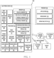
- the electronic device 101 may include a processor 120, memory 130, an input module 150, a sound output module 155, a display module 160, an audio module 170, a sensor module 176, an interface 177, a connecting terminal 178, a haptic module 179, a camera module 180, a power management module 188, a battery 189, a communication module 190, a subscriber identification module(SIM) 196, or an antenna module 197.
- at least one of the components e.g., the connecting terminal 178) may be omitted from the electronic device 101, or one or more other components may be added in the electronic device 101.
- some of the components e.g., the sensor module 176, the camera module 180, or the antenna module 197) may be implemented as a single component (e.g., the display module 160).
- the processor 120 may execute, for example, software (e.g., a program 140) to control at least one other component (e.g., a hardware or software component) of the electronic device 101 coupled with the processor 120, and may perform various data processing or computation. According to one embodiment, as at least part of the data processing or computation, the processor 120 may store a command or data received from another component (e.g., the sensor module 176 or the communication module 190) in volatile memory 132, process the command or the data stored in the volatile memory 132, and store resulting data in non-volatile memory 134.
- software e.g., a program 140
- the processor 120 may store a command or data received from another component (e.g., the sensor module 176 or the communication module 190) in volatile memory 132, process the command or the data stored in the volatile memory 132, and store resulting data in non-volatile memory 134.
- the processor 120 may include a main processor 121 (e.g., a central processing unit (CPU) or an application processor (AP)), or an auxiliary processor 123 (e.g., a graphics processing unit (GPU), a neural processing unit (NPU), an image signal processor (ISP), a sensor hub processor, or a communication processor (CP)) that is operable independently from, or in conjunction with, the main processor 121.
- a main processor 121 e.g., a central processing unit (CPU) or an application processor (AP)
- auxiliary processor 123 e.g., a graphics processing unit (GPU), a neural processing unit (NPU), an image signal processor (ISP), a sensor hub processor, or a communication processor (CP)
- the main processor 121 may be adapted to consume less power than the main processor 121, or to be specific to a specified function.
- the auxiliary processor 123 may be implemented as separate from, or as part of the main processor 121.
- the auxiliary processor 123 may control at least some of functions or states related to at least one component (e.g., the display module 160, the sensor module 176, or the communication module 190) among the components of the electronic device 101, instead of the main processor 121 while the main processor 121 is in an inactive (e.g., sleep) state, or together with the main processor 121 while the main processor 121 is in an active state (e.g., executing an application).
- the auxiliary processor 123 e.g., an image signal processor or a communication processor
- the auxiliary processor 123 may include a hardware structure specified for artificial intelligence model processing.
- An artificial intelligence model may be generated by machine learning. Such learning may be performed, e.g., by the electronic device 101 where the artificial intelligence is performed or via a separate server (e.g., the server 108). Learning algorithms may include, but are not limited to, e.g., supervised learning, unsupervised learning, semi-supervised learning, or reinforcement learning.
- the artificial intelligence model may include a plurality of artificial neural network layers.
- the artificial neural network may be a deep neural network (DNN), a convolutional neural network (CNN), a recurrent neural network (RNN), a restricted boltzmann machine (RBM), a deep belief network (DBN), a bidirectional recurrent deep neural network (BRDNN), deep Q-network or a combination of two or more thereof but is not limited thereto.
- the artificial intelligence model may, additionally or alternatively, include a software structure other than the hardware structure.
- the memory 130 may store various data used by at least one component (e.g., the processor 120 or the sensor module 176) of the electronic device 101.
- the various data may include, for example, software (e.g., the program 140) and input data or output data for a command related thererto.
- the memory 130 may include the volatile memory 132 or the non-volatile memory 134.
- the program 140 may be stored in the memory 130 as software, and may include, for example, an operating system (OS) 142, middleware 144, or an application 146.
- OS operating system
- middleware middleware
- application application
- the input module 150 may receive a command or data to be used by another component (e.g., the processor 120) of the electronic device 101, from the outside (e.g., a user) of the electronic device 101.
- the input module 150 may include, for example, a microphone, a mouse, a keyboard, a key (e.g., a button), or a digital pen (e.g., a stylus pen).
- the sound output module 155 may output sound signals to the outside of the electronic device 101.
- the sound output module 155 may include, for example, a speaker or a receiver.
- the speaker may be used for general purposes, such as playing multimedia or playing record.
- the receiver may be used for receiving incoming calls. According to an embodiment, the receiver may be implemented as separate from, or as part of the speaker.
- the display module 160 may visually provide information to the outside (e.g., a user) of the electronic device 101.
- the display module 160 may include, for example, a display, a hologram device, or a projector and control circuitry to control a corresponding one of the display, hologram device, and projector.
- the display module 160 may include a touch sensor adapted to detect a touch, or a pressure sensor adapted to measure the intensity of force incurred by the touch.
- the audio module 170 may convert a sound into an electrical signal and vice versa. According to an embodiment, the audio module 170 may obtain the sound via the input module 150, or output the sound via the sound output module 155 or a headphone of an external electronic device (e.g., an electronic device 102) directly (e.g., wiredly) or wirelessly coupled with the electronic device 101.
- an external electronic device e.g., an electronic device 102
- directly e.g., wiredly
- wirelessly e.g., wirelessly
- the sensor module 176 may detect an operational state (e.g., power or temperature) of the electronic device 101 or an environmental state (e.g., a state of a user) external to the electronic device 101, and then generate an electrical signal or data value corresponding to the detected state.
- the sensor module 176 may include, for example, a gesture sensor, a gyro sensor, an atmospheric pressure sensor, a magnetic sensor, an acceleration sensor, a grip sensor, a proximity sensor, a color sensor, an infrared (IR) sensor, a biometric sensor, a temperature sensor, a humidity sensor, or an illuminance sensor.
- the interface 177 may support one or more specified protocols to be used for the electronic device 101 to be coupled with the external electronic device (e.g., the electronic device 102) directly (e.g., wiredly) or wirelessly.
- the interface 177 may include, for example, a high definition multimedia interface (HDMI), a universal serial bus (USB) interface, a secure digital (SD) card interface, or an audio interface.
- HDMI high definition multimedia interface
- USB universal serial bus
- SD secure digital
- a connecting terminal 178 may include a connector via which the electronic device 101 may be physically connected with the external electronic device (e.g., the electronic device 102).
- the connecting terminal 178 may include, for example, a HDMI connector, a USB connector, a SD card connector, or an audio connector (e.g., a headphone connector).
- the haptic module 179 may convert an electrical signal into a mechanical stimulus (e.g., a vibration or a movement) or electrical stimulus which may be recognized by a user via his tactile sensation or kinesthetic sensation.
- the haptic module 179 may include, for example, a motor, a piezoelectric element, or an electric stimulator.
- the power management module 188 may manage power supplied to the electronic device 101.
- the power management module 188 may be implemented as at least part of, for example, a power management integrated circuit (PMIC).
- PMIC power management integrated circuit
- the battery 189 may supply power to at least one component of the electronic device 101.
- the battery 189 may include, for example, a primary cell which is not rechargeable, a secondary cell which is rechargeable, or a fuel cell.
- the communication module 190 may support establishing a direct (e.g., wired) communication channel or a wireless communication channel between the electronic device 101 and the external electronic device (e.g., the electronic device 102, the electronic device 104, or the server 108) and performing communication via the established communication channel.
- the communication module 190 may include one or more communication processors that are operable independently from the processor 120 (e.g., the application processor (AP)) and supports a direct (e.g., wired) communication or a wireless communication.
- AP application processor
- a corresponding one of these communication modules may communicate with the external electronic device via the first network 198 (e.g., a short-range communication network, such as Bluetooth TM , wireless-fidelity (Wi-Fi) direct, or infrared data association (IrDA)) or the second network 199 (e.g., a long-range communication network, such as a legacy cellular network, a 5G network, a next-generation communication network, the Internet, or a computer network (e.g., LAN or wide area network (WAN)).
- first network 198 e.g., a short-range communication network, such as Bluetooth TM , wireless-fidelity (Wi-Fi) direct, or infrared data association (IrDA)
- the second network 199 e.g., a long-range communication network, such as a legacy cellular network, a 5G network, a next-generation communication network, the Internet, or a computer network (e.g., LAN or wide area network (WAN)).
- the wireless communication module 192 may support a 5G network, after a 4G network, and next-generation communication technology, e.g., new radio (NR) access technology.
- the NR access technology may support enhanced mobile broadband (eMBB), massive machine type communications (mMTC), or ultra-reliable and low-latency communications (URLLC).
- eMBB enhanced mobile broadband
- mMTC massive machine type communications
- URLLC ultra-reliable and low-latency communications
- the wireless communication module 192 may support a high-frequency band (e.g., the mmWave band) to achieve, e.g., a high data transmission rate.
- the wireless communication module 192 may support a peak data rate (e.g., 20Gbps or more) for implementing eMBB, loss coverage (e.g., 164dB or less) for implementing mMTC, or U-plane latency (e.g., 0.5ms or less for each of downlink (DL) and uplink (UL), or a round trip of 1ms or less) for implementing URLLC.
- a peak data rate e.g., 20Gbps or more
- loss coverage e.g., 164dB or less
- U-plane latency e.g., 0.5ms or less for each of downlink (DL) and uplink (UL), or a round trip of 1ms or less
- the antenna module 197 may transmit or receive a signal or power to or from the outside (e.g., the external electronic device) of the electronic device 101.
- the antenna module 197 may include an antenna including a radiating element composed of a conductive material or a conductive pattern formed in or on a substrate (e.g., a printed circuit board (PCB)).
- the antenna module 197 may include a plurality of antennas (e.g., array antennas). In such a case, at least one antenna appropriate for a communication scheme used in the communication network, such as the first network 198 or the second network 199, may be selected, for example, by the communication module 190 (e.g., the wireless communication module 192) from the plurality of antennas.
- the signal or the power may then be transmitted or received between the communication module 190 and the external electronic device via the selected at least one antenna.
- another component e.g., a radio frequency integrated circuit (RFIC)
- RFIC radio frequency integrated circuit
- the antenna module 197 may form a mmWave antenna module.
- the mmWave antenna module may include a printed circuit board, a RFIC disposed on a first surface (e.g., the bottom surface) of the printed circuit board, or adj acent to the first surface and capable of supporting a designated high-frequency band (e.g., the mmWave band), and a plurality of antennas (e.g., array antennas) disposed on a second surface (e.g., the top or a side surface) of the printed circuit board, or adj acent to the second surface and capable of transmitting or receiving signals of the designated high-frequency band.
- a RFIC disposed on a first surface (e.g., the bottom surface) of the printed circuit board, or adj acent to the first surface and capable of supporting a designated high-frequency band (e.g., the mmWave band)
- a plurality of antennas e.g., array antennas
- At least some of the above-described components may be coupled mutually and communicate signals (e.g., commands or data) therebetween via an inter-peripheral communication scheme (e.g., a bus, general purpose input and output (GPIO), serial peripheral interface (SPI), or mobile industry processor interface (MIPI)).
- an inter-peripheral communication scheme e.g., a bus, general purpose input and output (GPIO), serial peripheral interface (SPI), or mobile industry processor interface (MIPI)
- the one or more external electronic devices receiving the request may perform the at least part of the function or the service requested, or an additional function or an additional service related to the request, and transfer an outcome of the performing to the electronic device 101.
- the electronic device 101 may provide the outcome, with or without further processing of the outcome, as at least part of a reply to the request.
- a cloud computing, distributed computing, mobile edge computing (MEC), or client-server computing technology may be used, for example.
- the electronic device 101 may provide ultra low-latency services using, e.g., distributed computing or mobile edge computing.
- the external electronic device 104 may include an internet-of-things (IoT) device.
- the server 108 may be an intelligent server using machine learning and/or a neural network.
- the external electronic device 104 or the server 108 may be included in the second network 199.
- the electronic device 101 may be applied to intelligent services (e.g., smart home, smart city, smart car, or healthcare) based on 5G communication technology or IoT-related technology.
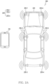
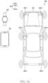
- FIG. 2A illustrates an example of an environment including an electronic device and at least one external electronic device, according to an embodiment.
- the electronic device 210 may communicate with at least one external electronic device 230 based on UWB communication and/or radio access technology (RAT) distinct from the UWB communication.
- the electronic device 210 may perform the UWB communication and/or Bluetooth communication (e.g., Bluetooth low energy (BLE) communication) with the at least one external electronic device 230.
- RAT radio access technology
- BLE Bluetooth low energy
- the external object 220 may include a processor for controlling at least one external electronic device 230.
- the external object 220 may control the at least one external electronic device 230 using the processor.
- the external objects 220 may include a component (e.g., a communication circuit) for communicating with an external device based on the RAT distinct from the UWB communication.
- the processor of the external object 220 may perform the Bluetooth communication (e.g., BLE communication) through the component (e.g., a communication circuit) for performing communication with the external device.
- At least one (e.g., the external electronic device 230-1) of the at least one external electronic device 230 includes a component for communicating with an external device based on the RAT distinct from the UWB communication.
- the electronic device 210 may perform a BLE scan operation.
- the electronic device 210 may perform the BLE scan operation to receive the BLE advertisement message.
- the electronic device 210 may exchange at least one parameter based on the BLE communication.
- the electronic device 210 may exchange at least one parameter for the UWB communication based on the BLE communication.
- the electronic device 210 may obtain at least one parameter for the UWB communication based on the BLE communication.
- the electronic device 210 may obtain a security key based on the at least one parameter for the UWB communication.
- the electronic device 210 may perform UWB communication with the at least one external electronic device 230 using the obtained security key.
- the external electronic device 230-1 may activate a communication circuit for the UWB communication.
- the external electronic device 230-1 may activate the communication circuit for the UWB communication, based on exchanging at least one parameter (e.g., the at least one parameter for the UWB communication) based on the BLE communication.
- the external electronic device 230-1 as well as the external electronic devices 230-2 to 230-6 may activate the communication circuit for the UWB communication.
- the external electronic device 230-1 may activate a communication circuit for the UWB communication between operations 252 and 253.
- the external electronic device 230-1 may activate a communication circuit for the UWB communication between operations 252 and 253.
- the electronic device 210 may transmit a pre-poll message to the at least one external electronic device 230.
- the electronic device 210 may broadcast (or multicast) the pre-poll message based on the UWB communication.
- Each of the at least one external electronic device 230 may receive a pre-poll message transmitted from the electronic device 210.
- the pre-poll message may be used to transmit control information on ranging operation.
- the pre-poll message may include at least one of UWB session ID information, Poll STS index information, ranging block information, hop flag information, and round index information.
- each of the at least one external electronic device 230 may transmit response messages to the electronic device 210.
- the at least one external electronic device 230 may transmit the response messages to the electronic device 210 based on a designated schedule.
- information on the designated schedule may be included in the pre-poll message.
- the designated schedule may be set by the processor of the external object 220.
- the electronic device 210 and the at least one external electronic device 230 may perform UWB ranging based on operations 255 to 259.
- the electronic device 210 and the at least one external electronic device 230 may perform 1:N (e.g., 1:6) double sided-two way ranging (DS-TWR).
- the electronic device 210 may operate as an initiator (or controller).
- the at least one external electronic device 230 may operate as a responder (or controlee).
- the electronic device 210 and the at least one external electronic device 230 may perform single sided-two way ranging (SS-TWR).
- SS-TWR single sided-two way ranging
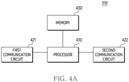
- the processor 410 may transmit a first signal to the second electronic device 320.
- the processor 410 may transmit a first signal including at least one parameter for UWB communication to the second electronic device 320 through the second communication circuit 422.
- a specific example of operation 493 will be described in operation 601 of FIG. 6A .
- the coordination of UWB communication between the first electronic device (310) and the second electronic device (320) is aimed at preventing collisions between UWB signals and increasing performance, based on limiting the number of electronic devices participating in UWB ranging.
- operation 520 may be performed in the second electronic device 320.
- operation 540 may be performed in the second electronic device 320.
- the processor 410 may determine a device having a larger remaining battery capacity as a device to perform the BLE scan operation based on remaining battery capacity. For example, based on identifying that a remaining battery capacity of the first electronic device 310 is larger than a remaining battery capacity of the second electronic device 320, the processor 410 may determine a device to perform the BLE scan operation as the first electronic device 310.
- the processor 410 may determine a device to perform the BLE scan operation as the first electronic device 310 of the first electronic device 310 and the second electronic device 320. For example, based on remaining battery capacity of the first electronic device 310 and remaining battery capacity of the second electronic device 320, the processor 410 may determine a device to perform the BLE scan operation as the first electronic device 310 of the first electronic device 310 and the second electronic device 320.
- the processor 410 may identify the external object 220 including at least one external electronic device 230. For example, the processor 410 may identify an external object 220 located around the first electronic device 310 based on the BLE scan operation through the second communication circuit 422. For example, the processor 410 may identify the external object 220 located around the first electronic device 310, based on receiving the BLE advertisement message from the external object 220 (e.g., the external electronic device 230-1).
- the processor 410 may identify the external object 220 including at least one external electronic device 230. For example, the processor 410 may identify an external object 220 located around the first electronic device 310 based on the BLE scan operation through the second communication circuit 422. For example, the processor 410 may identify the external object 220 located around the first electronic device 310, based on receiving the BLE advertisement message from the external object 220 (e.g., the external electronic device 230-1).
- the first electronic device 310 is determined as a device to perform the BLE scan operation is illustrated, but it is not limited thereto.
- a device preferentially received the BLE advertisement message may establish the BLE communication connection with the external electronic device 230-1.
- a high security level may be required to provide a service for controlling an operation of the external object 220.
- the processor 410 of the first electronic device 310 may perform a secure ranging operation with at least one external electronic device 230 included in the external object 220.
- a fixed key value may not be used, but a key value through signal exchange between electronic devices may be used, in order to obtain the first security key (e.g., UWB ranging secret key (URSK)) or a session key, which is an initial value for generating derivation keys used for scrambled timestamp sequence (STS) and payload encryption included in the UWB signal (or UWB frame).
- URSK UWB ranging secret key
- STS scrambled timestamp sequence
- the processor 410 may exchange the plurality of UWB signals according to a first period through the first communication circuit 421.
- the processor 410 may control the second electronic device 320 to sniff the plurality of UWB signals. For example, based on identifying that the first security key and the second security key are equally configurable, the processor 410 may control the second electronic device 320 to sniff at least a portion of the UWB signals exchanged between the first electronic device 310 and at least one external electronic device 230. A specific operation of the first electronic device 310 and the second electronic device 320 according to operations 570 and 580 will be described in FIGS. 6A to 8 .
- the processor 410 may exchange the plurality of UWB signals according to the first period, through the first communication circuit 421.
- the processor 410 may control the second electronic device 320 to exchange the plurality of other UWB signals according to the second period.
- operations 590 and 600 are illustrated to be performed sequentially, operations 590 and 600 may be performed simultaneously, or operations 600 may be performed earlier than operation 590.
- the processor 410 may control the second electronic device 320 so that the second electronic device 320 exchanges the plurality of other UWB signals with the at least one external electronic device 230.
- the processor 410 may control the second electronic device 320 to exchange the plurality of other UWB signals with the at least one external electronic device 230, based on identifying that the first security key and the second security key cannot be set the same.
- a specific operation of the first electronic device 310 and the second electronic device 320 according to operations 590 and 600 will be described in FIGS. 9A and 9B . It is also indicated that the NO branch of Fig. 5 , step 560 is fully optional and in an embodiment in step 560 the processor 410 only determines accordingly that the first security key and the second security key are equally configurable.
- operations 520 to 600 illustrated in FIG. 5 may be performed in various situations as well as operation 510. For example, based on identifying that at least one of the first security key (or a root key to obtain the first security key) and the second security key (or a root key to obtain the second security key) is deleted, the processor 410 may perform operations 520 to 600.
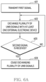
- FIG. 6A is a flowchart illustrating an operation of a first electronic device according to an embodiment.
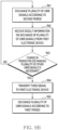
- FIG. 6B is a flowchart illustrating an operation of a second electronic device according to an embodiment.
- Operations 601 to 606 of FIG. 6A and operations 661 to 666 of FIG. 6B may be related to operations 570 and 580 of FIG. 5 .
- the processor 410 of the first electronic device 310 may perform operations 601 to 606, based on identifying that the first security key and the second security key are equally configurable.
- the processor 460 of the second electronic device 320 may perform operations 661 to 666, based on identifying that the first security key and the second security key are equally configurable.
- the processor 410 of the first electronic device 310 may transmit the first signal through the second communication circuit 422.
- the processor 410 may transmit the first signal including at least one parameter for UWB communication to the second electronic device 320, through the second communication circuit 422.
- the coordination of UWB communication between the first electronic device (310) and the second electronic device (320) is aimed at preventing collisions between UWB signals and increasing performance, based on limiting the number of electronic devices participating in UWB ranging.
- the processor 410 may establish (or generate) a session for UWB communication with the at least one external electronic device 230, through the first communication circuit 421.
- the processor 410 may exchange at least one parameter for UWB communication with the external electronic device 230-1, through BLE communication.
- the processor 410 may obtain at least one parameter through the BLE communication.
- the processor 410 may establish (or generate) a session for UWB communication, through the first communication circuit 421 based on at least one parameter.
- the processor 410 may transmit the first signal including at least one parameter to the second electronic device 320, by using RAT other than UWB communication.
- the processor 410 may transmit the first signal including at least one parameter to the second electronic device 320, by using the BLE communication, through the second communication circuit 422.
- the processor 410 of the first electronic device 310 may transmit the first signal including at least one parameter, through the first communication circuit 421.
- the processor 410 may exchange the plurality of UWB signals with the at least one external electronic device 230.
- the processor 410 may exchange the plurality of UWB signals with the at least one external electronic device 230, by using the first communication circuit 412.
- the processor 410 may perform UWB ranging by exchanging the plurality of UWB signals.
- the processor 410 may transmit a first UWB signal (e.g., a pre-poll message or a ranging control message (RCM)) and a second UWB signal (e.g., a poll message or a ranging initiation message (RIM)) to the at least one external electronic device 230, through the first communication circuit 421.
- a first UWB signal e.g., a pre-poll message or a ranging control message (RCM)
- a second UWB signal e.g., a poll message or a ranging initiation message (RIM)
- RRM ranging response message
- the processor 410 may transmit a fourth UWB signal (e.g., a final message or a ranging final message (RFM)) and a fifth UWB signal (e.g., a final_data message or a measurement report message (MRM)) to the at least one external electronic device 230, through the first communication circuit 421.
- the at least one external electronic device 230 may perform UWB ranging based on UWB signals transmitted and received with the first electronic device 310.
- the at least one external electronic device 230 may identify a location of the first electronic device 310 (or a location of a user possessing the first electronic device 310) based on UWB ranging.
- the exchange of the plurality of UWB signals may be performed based on a designated time interval (or the first period).
- the processor 410 may repeatedly exchange the plurality of UWB signals through the first communication circuit 421 according to the designated time interval (or the first period). For example, the processor 410 may perform UWB ranging, based on the designated time interval (or the first period), through the first communication circuit 421.
- the processor 410 may control the second electronic device 320 to identify (e.g., sniff) at least a portion of the plurality of UWB signals between the first electronic device 310 and the at least one external electronic device 230, by transmitting the first signal including at least one parameter to the second electronic device 320 through the second communication circuit 422.
- controlling the processor 410 through the first signal may indicate causing an operation of the second electronic device 320 through the first signal.
- the processor 410 may cause the second electronic device 320 to identify (e.g., sniff) at least a portion of the plurality of UWB signals between the first electronic device 310 and the at least one external electronic device 230, by transmitting the first signal to the second electronic device 320.
- the processor 410 may transmit and receive the plurality of UWB signals with the at least one external electronic device 230, based on the first security key (e.g., URSK or session key) through the first communication circuit 421.
- the processor 410 may transmit the first signal including at least one parameter to the second electronic device 320 through the second communication circuit 422 so that the second electronic device 320 obtains the second security key set equal to the first security key.
- the second electronic device 320 may establish (or generate) a session for UWB communication with the at least one external electronic device 230, by using the second security key set equal to the first security key.
- the second electronic device 320 may use a session for UWB communication between the first electronic device 310 and the at least one external electronic device 230, by using the second security key set equal to the first security key.
- the processor 410 may identify whether a service according to a location of a user possessing the first electronic device 310 and the second electronic device 320 is completed (or terminated). The processor 410 may identify whether the service is completed by identifying whether an operation of the external object 220 according to the location of the user possessing the first electronic device 310 and the second electronic device 320 is performed.
- the at least one external electronic device 230 may identify the location of the user possessing the first electronic device 310 and the second electronic device 320, based on identifying a location of the first electronic device 310.
- the at least one external electronic device 230 may perform a service according to the location of the user, based on the location of the user.
- the processor 410 may identify whether the second signal is received. For example, the processor 410 may identify whether the second signal is received, while exchanging the plurality of UWB signals with the at least one external electronic device 230. For example, the processor 410 may identify whether the second signal is received, based on identifying that the service according to the location of the user is not completed.
- the processor 410 may identify whether a second signal, to request the second electronic device 320 to exchange the plurality of other UWB signals with at least one external electronic device 230, is received from the second electronic device 320 through the first communication circuit 421 or the second communication circuit 422.
- the second signal may be a signal requesting a change in a device to perform UWB ranging with at least one external electronic device 230, from the first electronic device 310 to the second electronic device 320.
- the second signal may be a signal for causing change in a device to perform UWB ranging with the at least one external electronic device 230 from the first electronic device 310 to the second electronic device 320.
- the second signal may include information on the number of UWB signals identified by the second electronic device 320.
- the processor 410 may perform operation 602. For example, the processor 410 may perform operation 602 based on identifying that the second signal is not received. Consequently, the NO branch of step 603 is optional and in step 603 the processor 410 determines that the second signal has been received.
- the first signal may be used to control the second electronic device 320 to identify (or sniff) at least a portion of the plurality of UWB signals between the first electronic device 310 and the at least one external electronic device 230.
- the processor 460 may activate the first communication circuit 471 of the second electronic device 320 to sniff at least a portion of the UWB signals between the first electronic device 310 and the at least one external electronic device 230.
- the processor 460 may receive the first signal including at least one parameter from the first electronic device 310, by using RAT other than UWB communication.
- the processor 460 may receive the first signal including at least one parameter from the first electronic device 310, by using BLE communication through the second communication circuit 472.
- the processor 410 may cease sniffing the plurality of UWB signals, based on identifying that the service according to the location of the user is completed.
- the processor 460 may identify that the exchange of the plurality of UWB signals in the first electronic device 310 is terminated, based on identifying that the service according to the location of the user is completed. Accordingly, the processor 460 may cease sniffing the plurality of UWB signals through the first communication circuit 471.
- the processor 460 may identify whether exchange of the plurality of other UWB signals is necessary. For example, the processor 460 may identify whether the exchange of the plurality of other UWB signals is necessary, while sniffing the plurality of UWB signals. For example, the processor 460 may identify whether the exchange of the plurality of other UWB signals is necessary, based on identifying that the service according to the location of the user is not completed.
- the processor 460 may transmit the second signal. For example, based on identifying that the exchange of the plurality of UWB signals is required, the processor 460 may transmit the second signal to the first electronic device 310 through the first communication circuit 471 or the second communication circuit 472.
- the processor 460 may transmit the second signal to request that the second electronic device 320 exchanges the plurality of other UWB signals with at least one external electronic device 230, to the first electronic device 310.
- the processor 460 may exchange the plurality of other UWB signals with at least one external electronic device 230 through the first communication circuit 471, based on transmitting the second signal to the first electronic device 310 through the second communication circuit 472.
- FIG. 7 illustrates a signal flowchart between a first electronic device, a second electronic device, and at least one external electronic device, according to an embodiment.
- An operation in which the processor 460 of the second electronic device 320 transmits a signal may be described as an operation in which the second electronic device 320 transmits a signal through a communication circuit (e.g., the first communication circuit 471 or the second communication circuit 472).
- a communication circuit e.g., the first communication circuit 471 or the second communication circuit 472.
- An operation in which each of the processors of the at least one external electronic device 230 transmits a signal may be described as an operation in which each of the at least one external electronic device 230 transmits a signal through a communication circuit.
- the first electronic device 310 may transmit the second UWB signal to the at least one external electronic device 230.
- the first electronic device 310 may transmit the second UWB signal to the at least one external electronic device 230, by broadcasting (or multicasting) the second UWB signal.
- the second UWB signal may be referred to as a poll message or a ranging initiation message (RIM).
- the second UWB signal may include information for indicating the start of the first process (e.g., the ranging round or ranging operation).
- the first electronic device 310 may not receive all of the third UWB signals.
- the first electronic device 310 may receive at least a portion of the third UWB signals.
- the first electronic device 310 may identify an external electronic device transmitting at least a portion of the received third UWB signals.
- the second electronic device 320 may sniff the third UWB signals.
- the second electronic device 320 may identify the at least a portion of the third UWB signals transmitted from the at least one external electronic device 230.
- the second electronic device 320 may identify the second number of the at least a portion of the third UWB signals.
- the second electronic device 320 may identify information on signal quality of the third UWB signals.
- the first electronic device 310 may transmit information on the quality of the third UWB signals to the second electronic device 320.
- the second electronic device 320 may obtain information on the quality of the third UWB signals from the first electronic device 310.
- the first electronic device 310 may transmit a signal including information on the quality of the third UWB signals to the at least one external electronic device 230.
- the second electronic device may obtain information on the quality of the third UWB signals by sniffing the signal including information on the quality of the third UWB signals.
- the first electronic device 310 may transmit the fourth UWB signal to the at least one external electronic device 230.
- the first electronic device 310 may transmit a fourth UWB signal to at least one external electronic device 230, by broadcasting (or multicasting) the fourth UWB signal.
- the fourth UWB signal may be referred to as a final message or a ranging final message (RFM).
- the first electronic device 310 may transmit a fifth UWB signal to the at least one external electronic device 230.
- the first electronic device 310 may transmit the fifth UWB signal to the at least one external electronic device 230, by broadcasting (or multicasting) the fifth UWB signal.
- the fifth UWB signal may be referred to as a final_data message or a measurement report message (MRM).
- MRM measurement report message
- the fifth UWB signal may include information on at least a portion of the third UWB signals identified by the first electronic device 310.
- the processor 410 may include status information and/or timestamp information on the at least a portion of the third UWB signals.
- the second electronic device 320 may sniff the fifth UWB signal.
- the second electronic device 320 may sniff the fifth UWB signal to identify the first number of at least a portion of the third UWB signals identified in the first electronic device 310.
- the second electronic device 320 may identify the at least a portion of the third UWB signals identified in the first electronic device 310, based on the fifth UWB signal.
- the second electronic device 320 may identify the first number of the at least a portion of the third UWB signals identified in the first electronic device 310.
- the second electronic device 320 may compare a second number of at least a portion of the third UWB signals identified in the second electronic device 320 with the first number.
- Operation 706 and operation 716 may be omitted according to an embodiment.
- the external electronic device 230-1 may transmit a signal corresponding to the sixth UWB signal to the first electronic device 310, by using RAT (e.g., BLE communication) distinct from UWB communication.
- RAT e.g., BLE communication
- the second electronic device 320 may sniff only the first UWB signal, the third UWB signal, and the fifth UWB signal among the plurality of UWB signals.
- the second electronic device 320 may sniff only the first UWB signal, the third UWB signals, the fifth UWB signal, and the sixth UWB signal among the plurality of UWB signals.
- the second electronic device 320 may reduce power consumption by sniffing only a portion of the plurality of UWB signals. For example, the power consumption of the second electronic device 320 when only a portion of the plurality of UWB signals are sniffed may be reduced by half compared to power consumption when sniffing all of the plurality of UWB signals.
- the first electronic device 310 may identify a relative location of the first electronic device 310 with respect to the external object 220.
- the second electronic device 320 may also identify the relative location of the first electronic device 310 based on sniffing the sixth UWB signal. Based on identifying that a distance between the first electronic device 310 and the external object 220 is greater than or equal to a first designated distance, the second electronic device 320 may sniff only UWB signals with respect to a portion of a first processes (e.g., ranging block) that are repeated according to the first period.
- a first processes e.g., ranging block
- the second electronic device 320 may increase the number of the first processes (e.g., ranging block) for sniffing the UWB signals within a designated time. Based on identifying that the distance between the first electronic device 310 and the external object 220 is less than a second designated distance, the second electronic device 320 may sniff UWB signals with respect to all first processes repeated according to the first period.
- the first processes e.g., ranging block
- the second electronic device may transmit the signal 816 to the first electronic device 310.
- the first electronic device 310 may identify (e.g., sniff) at least a portion of the plurality of other UWB signals.
- the first electronic device 310 may perform the same or similar operations as operations performed by the second electronic device 320 in the first ranging block 810.
- the second electronic device 320 may identify (e.g., sniff) a portion of the UWB signals of the ranging blocks 810 repeated according to the first period.
- FIG. 9B is a flowchart illustrating an operation of a second electronic device, according to an embodiment.
- the processor 410 may control the second electronic device to exchange the plurality of other UWB signals according to the second period.
- the processor 410 may control the second electronic device 320 to exchange the plurality of other UWB signals according to the second period (e.g., 288 ms), while exchanging the plurality of UWB signals according to the first period (e.g., 96 ms).
- the first period may be set shorter than the second period.
- the first electronic device 310 may exchange the plurality of UWB signals at a higher frequency than the second electronic device 320.
- the second electronic device 320 may exchange the plurality of other UWB signals at a lower frequency than the first electronic device 310.
- the processor 410 may receive information indicating that the second session has been established from the second electronic device 320.
- the processor 410 may identify that the second electronic device 320 and at least one external electronic device 230 have established the second session based on the received information.
- the processor 410 may identify whether a service according to a location of a user possessing the first electronic device 310 and the second electronic device 320 is completed.
- the processor 410 may identify whether the service is completed by identifying whether an operation of the external object 220 according to the location of the user is performed.
- the processor 410 exchanges the plurality of UWB signals with the at least one external electronic device 230 according to the second period, but it is not limited thereto.
- the processor 410 may exchange the plurality of UWB signals with the at least one external electronic device 230 according to a third period distinct from the first period and the second period.
- the third period may be set longer than the first period.
- the processor 410 may determine a period for performing UWB ranging, based on priorities between electronic devices. For example, the processor 410 may set priorities of the first electronic device 310, the second electronic device 320, and the third electronic device (not illustrated). Security keys obtained in each of the first electronic device 310, the second electronic device 320, and the third electronic device (not illustrated) may be distinguished from each other.
- a period for the first electronic device 310 and/or the second electronic device 320 to exchange the plurality of other UWB signals with at least one external electronic device 230 may be changed based on a distance between a user possessing the first electronic device 310 and the external object 220. For example, as the distance between the user and the external object 220 becomes shorter, a period for exchanging the plurality of other UWB signals with the at least one external electronic device 230 may be set shorter.
- the processor 460 of the second electronic device 320 may exchange the plurality of other UWB signals with the at least one external electronic device 230 according to the second period.
- the processor 460 may receive a signal for controlling to exchange the plurality of other UWB signals according to the second period, from the first electronic device 310.
- the processor 460 may exchange the plurality of other UWB signals with at least one external electronic device 230 according to the second period, based on the received signal.
- the processor 460 may obtain result information on the exchange of the plurality of UWB signals by exchanging the plurality of other UWB signals with the at least one external electronic device 230 according to the second period.
- the result information on the exchange of the plurality of UWB signals may include information (or the number of timestamps included in the fifth UWB signal) on the second number of the at least a portion of the third UWB signals (e.g., a response message or RRM) among the plurality of UWB signals, identified in the second electronic device 310.
- the result information on the exchange of the plurality of UWB signals may include quality information of the plurality of UWB signals.
- the quality information of the plurality of UWB signals may include information on RSSI, SNR, and/or LoS of the plurality of UWB signals.
- the quality information of the plurality of UWB signals may include information on an average value (or intermediate values, maximum values, and minimum values) for a value (e.g., RSSI, SNR, and LoS) indicating the quality of the plurality of UWB signals.
- the processor 460 may identify whether the service according to the location of the user possessing the first electronic device 310 and the second electronic device 320 is completed.
- the processor 460 may identify whether the service is completed, by identifying whether an operation of the external object 220 according to the user's location is performed. Operation 962 may correspond to operation 603 of FIG. 6 .
- the processor 460 may transmit a third signal to the first electronic device 310.
- the processor 460 may transmit the third signal to the first electronic device 310, based on identifying that the change in the period for exchanging the plurality of other UWB signals is necessary.
- the processor 460 may transmit the third signal to change the period for exchanging the plurality of UWB signals in the first electronic device 310, to the first electronic device 310.
- the processor 460 may transmit the third signal to change the period for exchanging the plurality of UWB signals from the first period to the second period, to the first electronic device 310.
- the first electronic device 310 may perform operation 904.
- the second electronic device 320 may exchange the plurality of other UWB signals according to the first period.
- the processor 460 may exchange the plurality of other UWB signals with the at least one external electronic device 230 according to a fourth period distinct from the first period and the second period.
- the fourth period may be set shorter than the second period.
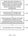
- FIG. 10A is a flowchart illustrating an operation of a first electronic device, according to an embodiment.
- FIG. 10B is a flowchart illustrating an operation of a second electronic device, according to an embodiment.
- the processor 410 of the first electronic device 310 may transmit a first signal for controlling the second electronic device 320 to identify at least a portion of a plurality of UWB signals between the first electronic device 310 and at least one external electronic device 230.
- the processor 410 may transmit the first signal for controlling the second electronic device 320 connected with the first device 320 to identify the at least a portion of the plurality of UWB signals between the first electronic device 310 and at least one external electronic device 230.
- the coordination of UWB communication between the first and the second electronic devices is aimed at preventing collisions between UWB signals and increasing performance, based on limiting the number of electronic devices participating in UWB ranging.
- the processor 410 may transmit the first signal to the second electronic device 320 through the second communication circuit 422, based on identifying that the first security key is the same as the second security key.
- the first signal may include information for the second electronic device 320 to sniff the plurality of UWB signals between the first electronic device 310 and the at least one external electronic device 230.
- the processor 410 may establish a connection with the at least one of the external electronic devices 230 (e.g., the external electronic device 230-1) through the second communication circuit 422.
- the processor 410 may obtain at least one parameter for performing UWB communication from at least one of the external electronic devices 230.
- the processor 410 may obtain the first security key based on at least one parameter.
- the processor 410 may transmit the at least one parameter to the second electronic device 320 so that the second electronic device 320 obtains the second security key identical to the first security key.
- the processor 410 may identify information on resources of the first electronic device 310 and information on resources of the second electronic device 320 before transmitting at least one parameter to the second electronic device 320.
- the processor 410 may determine a device for identifying an external object including at least one external electronic device 230 as at least one of the first electronic device 310 and the second electronic device 320, based on information on resources of the first electronic device 310 and information on resources of the second electronic device 320.
- the processor 410 may determine a device for performing a BLE scan operation as at least one of the first electronic device 310 and the second electronic device 320.
- the information on the resources of the second electronic device 320 may include at least one of information on the remaining battery capacity of the second electronic device 320, information on the number of external devices connected to the second electronic device 320, and information on a second scan period to identify the external object 220.
- the processor 410 may exchange the plurality of UWB signals with the at least one external electronic device 230.
- the processor 410 may transmit the first signal to the second electronic device 320 and then exchange the plurality of UWB signals with at least one external electronic device 230, through the first communication circuit 421.
- the processor 410 may transmit a second UWB signal (e.g., a poll message or RIM) to the at least one external electronic device 230.
- the processor 410 may transmit the second UWB signal to the at least one external electronic device 230, by broadcasting (or multicasting) the second UWB signal.
- the processor 410 may receive at least a portion of a third UWB signals (e.g., a response message or RRM) transmitted from each of the at least one external electronic device 230.
- a third UWB signals e.g., a response message or RRM
- the processor 410 may transmit result information on the exchange of the plurality of UWB signals performed according to the first period to the second electronic device 320.
- the result information on the exchange of the plurality of UWB signals may include at least one of information on the number (e.g., first number) of at the least a portion of the third UWB signals and quality information (e.g., SNR, RSSI, or LoS) on at least a portion of the third UWB signals.
- the processor 410 may transmit result information on the exchange of the plurality of UWB signals performed according to the first period, and then receive a third signal to change a period for exchanging the plurality of UWB signals from the second electronic device 320, through the second communication circuit 422.
- the processor 410 may change the period for exchanging the plurality of UWB signals from the first period to the second period, based on the third signal.
- the second electronic device 320 may change the period for exchanging the plurality of other UWB signals from the second period to the first period, based on transmitting the third signal.
- the first period may be set shorter than the second period.
- the processor 460 of the second electronic device 320 may receive a first signal to control that the second electronic device 320 identifies at least a portion of a plurality of UWB signals between the first electronic device 310 and at least one external electronic device 230, from the first electronic device 310. According to an embodiment, the processor 460 may identify whether the first security key for the first electronic device 310 used for UWB communication is the same as the second security key for the second electronic device 320.
- the processor 460 may receive a first signal to control that the second electronic device 320 identifies at least a portion of the plurality of UWB signals between the first electronic device 310 and at least one external electronic device 230, from the first electronic device 310.
- the processor 460 may identify (e.g., sniff) the first UWB signal, at least a portion of the third UWB signals, and the fifth UWB signal among the plurality of UWB signals.
- the processor 460 may identify result information on the exchange of the plurality of UWB signals. For example, the processor 460 may identify result information on the exchange of the plurality of UWB signals, based on at least a portion of the plurality of UWB signals. For example, the processor 460 may identify the first number of at least a portion of the third UWB signals identified by the first electronic device 310, based on the number of time stamps included in the fifth UWB signal.
- the processor 460 may transmit a second signal to request that the second electronic device 320 exchanges the plurality of other UWB signals with at least one external electronic device 230, to the first electronic device 310. For example, based on the result information on the exchange of the plurality of UWB signals, the processor 460 may transmit a second signal to request that the second electronic device 320 exchanges the plurality of other UWB signals with at least one external electronic device 230, to the first electronic device 310 through the second communication circuit 422.
- the processor 460 may transmit the second signal to the first electronic device 310.
- the processor 460 may exchange the plurality of other UWB signals with at least one external electronic device 230.
- the processor 460 may exchange the plurality of other UWB signals with at least one external electronic device 230, based on transmitting the second signal.
- the processor 460 may cease UWB ranging performed in the first electronic device 310 and perform UWB ranging in the second electronic device 320.
- the processor 410 may be configured to transmit, through the second communication circuit 422, a first signal for controlling a second electronic device 320, which is connected with the first electronic device 310, to identify at least a portion of a plurality of UWB signals between the first electronic device 310 and at least one external electronic device 230, to the second electronic device 320.
- the processor 410 may be configured to, after transmitting the first signal to the second electronic device 320, exchange, through the first communication circuit 421, the plurality of UWB signals with the at least one external electronic device 230.
- the processor 410 may be configured to receive a second signal for requesting to exchange a plurality of other UWB signals with the at least one external electronic device 230 from the second electronic device 320 based on the exchange of the plurality of UWB signals.
- the processor 410 may be configured to cease, based on the second signal, exchanging of the plurality of UWB signals.
- the processor 410 may be configured to identify whether a first security key for the first electronic device 310 used for the UWB communication is the same as a second security key for the second electronic device 320.
- the processor 410 may be configured to transmit, through the second communication circuit 422, the first signal to the second electronic device 320, based on identifying that the first security key is the same as the second security key.
- the first signal may comprise information for the second electronic device 320 to sniff by the plurality of UWB signals between the first electronic device 310 and at least one external electronic device 230.
- the processor 410 may be configured to establish, through the second communication circuit 422, a connection with at least one of the at least one external electronic device 230.
- the processor 410 may be configured to obtain at least one parameter for performing the UWB communication, from the at least one of the at least one external electronic device 230.
- the processor 410 may be configured to obtain, based on the at least one parameter, the first security key.
- the processor 410 may be configured to exchange, based on identifying that the first security key is distinct from the second security key, the plurality of UWB signals according to first period.
- the processor 410 may be configured to transmit, to the second electronic device 320, result information on exchanging the plurality of UWB signals performed according to the first period.
- the processor 410 may be configured to identify, based on exchanging the plurality of UWB signals, location of the first electronic device 310.
- the processor 410 may be configured to transmit a signal for controlling the second electronic device 320 to cease exchanging of the plurality of other UWB signals, based on a distance between location of the first electronic device 310 and location of external object comprising the at least one external electronic device 230 is equal to or greater than a predetermined distance.
- the processor 410 may be configured to identify information on resource of the first electronic device 310 and information on resource of the second electronic device 320.
- the processor 410 may be configured to determine a device for identifying an external object comprising the at least one external electronic device 230 as at least one of the first electronic device 310 and the second electronic device 320 based on the information on resource of the first electronic device 310 and the information on resource of the second electronic device 320.
- the information on resource of the first electronic device 310 may include at least one of information on remaining battery capacity of the first electronic device 310, information on the number of external devices connected to the first electronic device 310, or information on a first scan period for identifying the external object.
- the information on resource of the second electronic device 320 may include at least one of information on remaining battery capacity of the second electronic device 320, information on the number of external devices connected to the second electronic device 320, or information on a second scan period for identifying the external object.
- a method of a first electronic device 310 may comprise transmitting, through a second communication circuit 422 of a first communication circuit 421 and the second communication circuit 422 of the first electronic device 310, a first signal for controlling a second electronic device 320, which is connected with the first electronic device 310, to identify at least a portion of a plurality of UWB signals between the first electronic device 310 and at least one external electronic device 230, to the second electronic device 320.
- the method may comprise, after transmitting the first signal to the second electronic device 320, exchanging, through the first communication circuit 421, the plurality of UWB signals with the at least one external electronic device 230.
- the processor 410 of the first electronic device 310 may limit the number of electronic devices participating in UWB ranging.
- the processor 410 may prevent collisions between UWB signals and increase performance, based on limiting the number of electronic devices participating in UWB ranging.
- an element e.g., a first element
- the element may be coupled with the other element directly (e.g., wiredly), wirelessly, or via a third element.
- the machine-readable storage medium may be provided in the form of a non-transitory storage medium.
- non-transitory simply means that the storage medium is a tangible device, and does not include a signal (e.g., an electromagnetic wave), but this term does not differentiate between where data is semi-permanently stored in the storage medium and where the data is temporarily stored in the storage medium.
Landscapes
- Engineering & Computer Science (AREA)
- Computer Networks & Wireless Communication (AREA)
- Signal Processing (AREA)
- Computer Security & Cryptography (AREA)
- Mobile Radio Communication Systems (AREA)
Applications Claiming Priority (3)
| Application Number | Priority Date | Filing Date | Title |
|---|---|---|---|
| KR20220158802 | 2022-11-23 | ||
| KR1020230010693A KR20240077367A (ko) | 2022-11-23 | 2023-01-27 | 전자 장치의 위치에 따른 서비스를 제공하기 위한 전자 장치 및 방법 |
| PCT/KR2023/014710 WO2024111852A1 (fr) | 2022-11-23 | 2023-09-25 | Dispositif électronique et procédé de fourniture de service en fonction de la position du dispositif électronique |
Publications (2)
| Publication Number | Publication Date |
|---|---|
| EP4398670A1 true EP4398670A1 (fr) | 2024-07-10 |
| EP4398670A4 EP4398670A4 (fr) | 2024-07-10 |
Family
ID=88505183
Family Applications (1)
| Application Number | Title | Priority Date | Filing Date |
|---|---|---|---|
| EP23782126.9A Pending EP4398670A4 (fr) | 2022-11-23 | 2023-09-25 | Dispositif électronique et procédé de fourniture de service en fonction de la position du dispositif électronique |
Country Status (2)
| Country | Link |
|---|---|
| EP (1) | EP4398670A4 (fr) |
| WO (1) | WO2024111852A1 (fr) |
Family Cites Families (6)
| Publication number | Priority date | Publication date | Assignee | Title |
|---|---|---|---|---|
| EP3425867B1 (fr) * | 2017-07-05 | 2021-01-13 | Nxp B.V. | Dispositifs de communication et procédé associé |
| WO2020145526A1 (fr) * | 2019-01-08 | 2020-07-16 | 삼성전자 주식회사 | Dispositif électronique pour effectuer une télémétrie sur une bande ultralarge (uwb) et procédé pour faire fonctionner un dispositif électronique |
| US11184810B2 (en) * | 2019-08-14 | 2021-11-23 | Apple Inc. | Ultra wideband range extension |
| US11470444B2 (en) * | 2020-06-18 | 2022-10-11 | Apple Inc. | Communication techniques using passive beacons |
| KR102929065B1 (ko) * | 2021-04-09 | 2026-02-23 | 삼성전자주식회사 | 블루투스 통신 품질 공유에 기반한 초광대역 통신 방법 및 이를 위한 전자 장치 |
| KR20220152779A (ko) * | 2021-05-10 | 2022-11-17 | 삼성전자주식회사 | 전자 장치 및 이를 이용한 외부 전자 장치의 업데이트 방법 |
-
2023
- 2023-09-25 EP EP23782126.9A patent/EP4398670A4/fr active Pending
- 2023-09-25 WO PCT/KR2023/014710 patent/WO2024111852A1/fr not_active Ceased
Also Published As
| Publication number | Publication date |
|---|---|
| EP4398670A4 (fr) | 2024-07-10 |
| WO2024111852A1 (fr) | 2024-05-30 |
Similar Documents
| Publication | Publication Date | Title |
|---|---|---|
| EP4120794B1 (fr) | Dispositif électronique utilisant une pluralité de schémas de communication et son procédé de commande | |
| US20230362795A1 (en) | Electronic device for broadcasting advertisement packets together with counterpart electronic device, and operating method thereof | |
| US12568545B2 (en) | Ultra-wideband communication method based on Bluetooth communication quality sharing and electronic device therefor | |
| US12445834B2 (en) | Electronic device performing wireless communication with accessory device, and operating method thereof | |
| US20240365222A1 (en) | Method for setting available channels for wlan and electronic device for performing same method | |
| EP4175354A1 (fr) | Dispositif électronique et procédé de réalisation de communication à l'aide de celui-ci | |
| US12363519B2 (en) | Apparatus and method for establishing a connection | |
| US20230291559A1 (en) | Electronic device for controlling power consumption of accessory device and operating method therefor | |
| US20260032579A1 (en) | Method and electronic device for communicating based on access point | |
| US12231557B2 (en) | Method for performing shared secret key renewing and electronic device for supporting same | |
| EP4262236A1 (fr) | Dispositif électronique permettant de traiter des données audio, et procédé de fonctionnement associé | |
| KR102907199B1 (ko) | 계정 정보 기반한 초광대역 통신 방법 및 이를 위한 전자 장치 | |
| US12432656B2 (en) | Electronic device for performing SA query in WLAN system and operating method thereof | |
| EP4398670A1 (fr) | Dispositif électronique et procédé de fourniture de service en fonction de la position du dispositif électronique | |
| EP4607847A1 (fr) | Dispositif électronique, et procédé de téléchargement de données à partir d'un dispositif électronique externe vers un dispositif électronique | |
| EP4401502A1 (fr) | Dispositif électronique permettant une communication de lan sans fil avec une pluralité d'appareils externes et procédé de fonctionnement du dispositif électronique | |
| EP4266823A1 (fr) | Dispositif électronique permettant d'établir une connexion de communication à un dispositif électronique externe et son procédé de fonctionnement | |
| KR20240077367A (ko) | 전자 장치의 위치에 따른 서비스를 제공하기 위한 전자 장치 및 방법 | |
| EP4346321A1 (fr) | Dispositif électronique, procédé et support de stockage non transitoire lisible par ordinateur pour effectuer un processus de publicité synchronisé avec un processus de publicité dans un autre dispositif électronique | |
| EP4709028A1 (fr) | Dispositif électronique pour une communication lan sans fil et procédé de fonctionnement associé | |
| US12432548B2 (en) | Method of managing electronic devices based on group account and electronic device for providing the same | |
| EP4481536A1 (fr) | Dispositif électronique et procédé de transmission d'informations relatives à une charge d'une batterie dans un dispositif électronique | |
| EP4521846A1 (fr) | Dispositif électronique et procédé de formation d'un groupe p2p wi-fi de celui-ci | |
| US20250358267A1 (en) | Electronic device for wireless communication, and operational method thereof | |
| US20250165738A1 (en) | File transmission system, electronic device, and file transmission method by same electronic device |
Legal Events
| Date | Code | Title | Description |
|---|---|---|---|
| STAA | Information on the status of an ep patent application or granted ep patent |
Free format text: STATUS: UNKNOWN |
|
| STAA | Information on the status of an ep patent application or granted ep patent |
Free format text: STATUS: THE INTERNATIONAL PUBLICATION HAS BEEN MADE |
|
| PUAI | Public reference made under article 153(3) epc to a published international application that has entered the european phase |
Free format text: ORIGINAL CODE: 0009012 |
|
| STAA | Information on the status of an ep patent application or granted ep patent |
Free format text: STATUS: REQUEST FOR EXAMINATION WAS MADE |
|
| 17P | Request for examination filed |
Effective date: 20231009 |
|
| A4 | Supplementary search report drawn up and despatched |
Effective date: 20240528 |
|
| AK | Designated contracting states |
Kind code of ref document: A1 Designated state(s): AL AT BE BG CH CY CZ DE DK EE ES FI FR GB GR HR HU IE IS IT LI LT LU LV MC ME MK MT NL NO PL PT RO RS SE SI SK SM TR |
|
| DAV | Request for validation of the european patent (deleted) | ||
| DAX | Request for extension of the european patent (deleted) |