EP4400013A1 - Libération de liquide au niveau d'un côté inférieur d'une buse de nettoyage humide - Google Patents
Libération de liquide au niveau d'un côté inférieur d'une buse de nettoyage humide Download PDFInfo
- Publication number
- EP4400013A1 EP4400013A1 EP23151262.5A EP23151262A EP4400013A1 EP 4400013 A1 EP4400013 A1 EP 4400013A1 EP 23151262 A EP23151262 A EP 23151262A EP 4400013 A1 EP4400013 A1 EP 4400013A1
- Authority
- EP
- European Patent Office
- Prior art keywords
- cleaning nozzle
- wet cleaning
- liquid
- cleaned
- wet
- Prior art date
- Legal status (The legal status is an assumption and is not a legal conclusion. Google has not performed a legal analysis and makes no representation as to the accuracy of the status listed.)
- Withdrawn
Links
Images


Classifications
-
- A—HUMAN NECESSITIES
- A47—FURNITURE; DOMESTIC ARTICLES OR APPLIANCES; COFFEE MILLS; SPICE MILLS; SUCTION CLEANERS IN GENERAL
- A47L—DOMESTIC WASHING OR CLEANING; SUCTION CLEANERS IN GENERAL
- A47L5/00—Structural features of suction cleaners
- A47L5/12—Structural features of suction cleaners with power-driven air-pumps or air-compressors, e.g. driven by motor vehicle engine vacuum
- A47L5/22—Structural features of suction cleaners with power-driven air-pumps or air-compressors, e.g. driven by motor vehicle engine vacuum with rotary fans
- A47L5/28—Suction cleaners with handles and nozzles fixed on the casings, e.g. wheeled suction cleaners with steering handle
- A47L5/30—Suction cleaners with handles and nozzles fixed on the casings, e.g. wheeled suction cleaners with steering handle with driven dust-loosening tools, e.g. rotating brushes
-
- A—HUMAN NECESSITIES
- A47—FURNITURE; DOMESTIC ARTICLES OR APPLIANCES; COFFEE MILLS; SPICE MILLS; SUCTION CLEANERS IN GENERAL
- A47L—DOMESTIC WASHING OR CLEANING; SUCTION CLEANERS IN GENERAL
- A47L11/00—Machines for cleaning floors, carpets, furniture, walls, or wall coverings
- A47L11/40—Parts or details of machines not provided for in groups A47L11/02 - A47L11/38, or not restricted to one of these groups, e.g. handles, arrangements of switches, skirts, buffers, levers
- A47L11/408—Means for supplying cleaning or surface treating agents
-
- A—HUMAN NECESSITIES
- A47—FURNITURE; DOMESTIC ARTICLES OR APPLIANCES; COFFEE MILLS; SPICE MILLS; SUCTION CLEANERS IN GENERAL
- A47L—DOMESTIC WASHING OR CLEANING; SUCTION CLEANERS IN GENERAL
- A47L9/00—Details or accessories of suction cleaners, e.g. mechanical means for controlling the suction or for effecting pulsating action; Storing devices specially adapted to suction cleaners or parts thereof; Carrying-vehicles specially adapted for suction cleaners
- A47L9/02—Nozzles
- A47L9/04—Nozzles with driven brushes or agitators
- A47L9/0461—Dust-loosening tools, e.g. agitators, brushes
- A47L9/0466—Rotating tools
- A47L9/0477—Rolls
Definitions
- the invention relates to a wet cleaning nozzle that is configured to be applied in a cleaning appliance and to perform a cleaning action on a surface
- the wet cleaning nozzle comprising: 1) at least one surface contacting element that is arranged and configured to be in contact with the surface to be cleaned through at least one contacting area, wherein the at least one contacting area on the at least one surface contacting element defines a surface interface level of the wet cleaning nozzle, and 2) a wetting arrangement that is arranged and configured to enable a supply of liquid to at least one area of the surface to be cleaned by releasing liquid at a liquid release position at a bottom side of the wet cleaning nozzle that is configured to face the at least one area of the surface to be cleaned.
- the invention relates to a cordless vacuum cleaner comprising a wet cleaning nozzle as mentioned.
- Cleaning appliances for cleaning surfaces are generally known and come in various forms, wherein a vacuum cleaner and a mopping appliance are practical examples.
- the cleaning appliance functions to remove dirt as may be present on the surface from the surface.
- the term "dirt" as used in the present text is to be understood so as to cover any contamination as may be present on a surface such as dust and small particles of any kind, and also wet types of contamination such as spilled drinks.
- a practical example of a surface to be cleaned is a floor, wherein the floor may be of any kind, such as a wooden floor, a carpet floor, a tile floor, etc.
- a wet cleaning nozzle constitutes the part of the vacuum cleaner where the actual process of picking up dirt from a surface to be cleaned is to take place.
- the wet cleaning nozzle is to be put on or at least close to the surface.
- a vacuum cleaner normally comprises a body portion including a dirt accumulating area, and an arrangement that is configured to act on the wet cleaning nozzle so that a suction force is prevailing in the wet cleaning nozzle during operation of the vacuum cleaner.
- the suction force serves to facilitate transport of dirt that is picked up from the surface during operation of the vacuum cleaner towards the dirt accumulating area, wherein the dirt is made to pass an outlet opening in a housing of the wet cleaning nozzle.
- the suction force may also have a function in the actual process of picking up the dirt from the surface.
- the wet cleaning nozzle may be equipped with at least one movable component for interacting with the surface in order to pick up the dirt, such as at least one rotatable brush that may serve as an agitator of the dirt and that may particularly be configured to help dislodge dirt from the surface and direct it towards the outlet opening.
- WO 2022/194717 A1 discloses a wet cleaning nozzle that comprises a housing that includes a coupling area that is configured to enable coupling of the housing to an air suction source of a vacuum cleaner, at least one brush that is rotatably arranged in the housing and configured to interact with a surface to be cleaned, and at least one wheel that is rotatably arranged on the wet cleaning nozzle and configured to be in contact with the surface.
- the wet cleaning nozzle is further equipped with a wetting arrangement that is configured to enable a direct supply of liquid to the at least one wheel and to thereby achieve the effect that the at least one wheel is kept wet, which is a factor in achieving good cleaning results.
- the wetting arrangement may further be arranged and configured to enable a direct supply of liquid to at least one area of the surface to be cleaned.
- the at least one brush is preferably of a very open structure and is rotated at a high speed, such as 4,500 rpm, so that it is achieved that absorption of liquid in the brush is minimal, yet sufficient to always keep the brush clean.
- the invention provides a wet cleaning nozzle that is configured to be applied in a cleaning appliance and to perform a cleaning action on a surface
- the wet cleaning nozzle comprising: 1) at least one surface contacting element that is arranged and configured to be in contact with the surface to be cleaned through at least one contacting area, wherein the at least one contacting area on the at least one surface contacting element defines a surface interface level of the wet cleaning nozzle, and 2) a wetting arrangement that is arranged and configured to enable a supply of liquid to at least one area of the surface to be cleaned by releasing liquid at a liquid release position at a bottom side of the wet cleaning nozzle that is configured to face the at least one area of the surface to be cleaned, wherein the liquid release position is at a level of less than 2 mm above the surface interface level.
- a practical example of the at least one surface contacting element mentioned in the foregoing definition of the wet cleaning nozzle according to the invention is at least one wheel, such as known from WO 2022/194717 A1 .
- the at least one contacting area on the at least one surface contacting element is the actual area that is at the lowest position of the at least one wheel, which is exactly the area through which the at least one wheel contacts a surface to be cleaned when the wet cleaning nozzle is used on the surface.
- Another practical example of the at least one surface contacting element is at least one element designed to function as a slider, in which case the at least one contacting area on the at least one surface contacting element is the actual sliding surface of the slider.
- the wetting arrangement can be provided more or less as an add-on to an existing design of a wet cleaning nozzle, but it is also possible that the wetting arrangement is provided in a more integrated fashion.
- Practical examples of the liquid are water and a mixture of water and a cleaning agent.
- the at least one contacting area on the at least one surface contacting element defines a surface interface level of the wet cleaning nozzle.
- the surface interface level corresponds to the actual level of a surface to be cleaned when the wet cleaning nozzle is used on the surface.
- a notable feature of the wet cleaning nozzle according to the invention is that the position where liquid is released during operation of the wet cleaning nozzle is at a level of less than 2 mm above the surface interface level. According to an insight of the invention, when a distance of the liquid release position to the surface to be cleaned is larger, there is a risk that liquid that is supposed to reach the surface is directly transported to inside the wet cleaning nozzle.
- this is relevant in the context of vacuum cleaning, in which case it happens that direct transport of liquid takes place under the influence of suction forces and adhesive forces between the liquid and material of the wet cleaning nozzle situated between the liquid release position and a position where the interior of the wet cleaning nozzle is accessible to a suction flow.
- the wet cleaning nozzle is equipped with at least one movable component for interacting with the surface to be cleaned, such as a rotatable brush, there is also a risk that the liquid is picked up by such component before reaching the surface.
- the distance between the liquid release position and the surface interface level is about 1.5 mm, or in a range of 1.4 mm to 1.9 mm. Further, it may be practical if a minimum of 0.5 mm is applied in respect of the distance between the liquid release position and the surface interface level. Generally speaking, embodiments of the wet cleaning nozzle are feasible in which the level of the liquid release position differs from the surface interface level.
- the wetting arrangement comprises a conduit system that is configured to transport liquid through the wet cleaning nozzle.
- a portion of a conduit of the wetting arrangement being an end portion including the end of the conduit protrudes relative to a bottom surface of the wet cleaning nozzle. This allows for having the bottom surface at a practical level above the surface interface level, wherein a maximum of 5 mm above the surface interface level may be applicable, while the liquid release position can still be at the level of less than 2 mm above the surface interface level.
- at least the end portion of the conduit is flexible, so that damage to the conduit and/or the surface to be cleaned is avoided.
- At least the end portion of the conduit may be made from a rubber material, wherein a nitrile rubber with 50 Shore A hardness is a practical example. Rubber also has good shock absorbing properties, which is useful in view of the possibility of hitting an object on the surface to be cleaned. To even further reduce the shock in such a case, a relatively small wall thickness, such as a wall thickness of about 1 mm, can be chosen in respect of the at least the end portion of the conduit.
- An alternative measure aimed at ensuring that liquid reaches the surface to be cleaned involves equipping the wet cleaning nozzle with at least one element extending from a conduit of the wetting arrangement in a generally downward direction.
- Such an element serves as a bridging element along/through which the liquid is transported towards the surface, so that a defined route of the liquid to the surface is realized and the risk of the liquid following another route is minimized, wherein the liquid release position is at a free end of the element.
- the at least one element is preferably flexible for the reasons mentioned in the foregoing, and may comprise porous material.
- a practical embodiment of the at least one element is an embodiment in which the at least one element comprises a flexible wire composed of a number of fibres.
- the liquid release position is at a hole in the bottom surface.
- at least a portion of a component of the wet cleaning nozzle including the bottom surface and the hole is flexible.
- the wet cleaning nozzle comprises at least one brush that is rotatably arranged in the wet cleaning nozzle and configured to interact with the surface to be cleaned.
- the at least one brush may be of any type that is suitable to be used for picking up dirt from a surface to be cleaned.
- the brush may especially be designed to serve as an agitator, for example, agitating dirt particles as may be present on the surface.
- the brush comprises a core element and flexible microfiber elements arranged on the core element.
- a linear mass density lower than 150 g per 10 km may be applicable to the microfiber elements, or at least tip portions thereof, so that the microfiber elements really can be highly flexible.
- the linear mass density as mentioned may even be lower than 10 g per 10 km, 5 g per 10 km or 1 g per 10 km.
- Such microfiber elements can be placed on the core element in a dense arrangement so as to very effectively interact with a surface to be cleaned during operation of the wet cleaning nozzle. Further, such microfiber elements can be arranged on the core element in tufts. Also, it is practical if an operational shape of the brush is generally the shape of a cylinder having a circular periphery, in other words, if the operational shape of the brush is generally the shape of a roller, which may be an elongated roller.
- the wet cleaning nozzle comprises two brushes in a substantially parallel arrangement and two squeegees in an area between the brushes.
- the wet cleaning nozzle comprises a bottom cover
- the squeegees are arranged on the bottom cover and extend along opposite sides of the bottom cover. Having the combination of the two brushes and the two squeegees helps in creating a scraping effect on the surface to be cleaned so that thick substances such as syrup and dried stains can be removed without a need for increasing energy consumption.
- having the combination of the two brushes and the two squeegees may help in improving distribution of liquid on the surface, in improving absorbance or irregularities on the surface so that a situation of the wet cleaning nozzle bouncing off the surface and leaving dirt or liquid behind is avoided, and also in improving the self-cleaning capabilities of the wet cleaning nozzle during normal use and during a possible auto-clean program on the basis of an increased amount of liquid that is made to reflow through the wet cleaning nozzle.
- the invention further relates to a vacuum cleaner, particularly a cordless vacuum cleaner, comprising a wet cleaning nozzle as defined and described in the foregoing, i.e. a wet cleaning nozzle designed to release liquid to a surface to be cleaned at a level of less than 2 mm above the surface.
- a vacuum cleaner comprises a reservoir that is configured to receive liquid, to contain liquid, and to let out liquid to the wetting arrangement included in the wet cleaning nozzle.
- the reservoir is removably arranged on the vacuum cleaner so that it is easy for a user to take the reservoir to a place where the reservoir can be filled with liquid.
- the wet cleaning nozzle comprises a housing that includes a coupling area that is configured to enable coupling of the housing to an air suction source of a vacuum cleaner.
- a wet cleaning nozzle comprising a housing and two brushes arranged in the housing, and further comprising a wetting arrangement that is arranged and configured to enable a supply of liquid both directly to areas of a surface to be cleaned and indirectly to further areas of the surface through wheels of the wet cleaning nozzle.
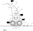
- Figure 1 illustrates the design of a wet vacuum cleaner 100 according to an embodiment of the invention.
- the particular vacuum cleaner represented in figure 1 and described in the following is just one example of many types of cleaning appliances that are feasible in the framework of the invention.
- the invention does not only relate to wet vacuum cleaners, but also to other types of vacuum cleaners such as wet/dry vacuum cleaners having a dry cleaning function besides a wet cleaning function, and to other types of cleaning appliances such as mopping appliances, wherein reference is made to EP 3366182 A1 .
- the wet vacuum cleaner 100 is configured to be used for the purpose of subjecting a surface 10 such as a floor surface to a wet cleaning action.
- Figure 1 shows the vacuum cleaner 100 in a normal, operational orientation relative to the surface 10 to be cleaned.
- the use in the present text of a term having an orientation aspect is to be understood in relation to this normal, operational orientation of the vacuum cleaner 100 relative to the surface 10 to be cleaned, wherein it is assumed that the surface 10 is at a bottom position and the vacuum cleaner 100 is placed on the surface 10.
- the vacuum cleaner 100 comprises a wet cleaning nozzle 101.
- the wet cleaning nozzle 101 accommodates two brushes 20 that are configured to interact with the surface 10 during operation of the vacuum cleaner 100.
- the wet cleaning nozzle 101 comprises a housing 30 that is configured to partially cover the brushes 20.
- the housing 30 can be made of a plastic material, for example.
- each of the brushes 20 is provided in the form of a roller that is rotatable about a rotation axis 21 defined by a central longitudinal axis of the roller, and that each of the brushes 20 comprises a core element 22 and flexible microfiber elements 23 arranged on the core element 22, which does not alter the fact that other embodiments of the brushes 20 are possible as well.
- the brushes 20 may be identical, but this is not necessary in the context of the invention. As indicated in figure 1 by means of curved arrows depicted at the position of the brushes 20, the brushes 20 are arranged so as to be rotatable in opposite directions with respect to each other about their respective rotation axes 21.
- the wet cleaning nozzle 101 may accommodate another number of brushes 20, wherein it is particularly to be noted that having just a single brush 20 is a feasible alternative option.
- a wet cleaning nozzle 10 that is without any brush 20 is also covered by the invention.
- the vacuum cleaner 100 comprises a body portion 102 that is configured to be taken hold of by a user of the vacuum cleaner 100.
- the wet cleaning nozzle 101 and the body portion 102 are removably couplable to each other.
- the body portion 102 can be shaped in any appropriate way.
- the outline of the body portion 102 as shown in figure 1 is of a diagrammatical nature only. It is practical if the body portion 102 comprises a handle so that a user can easily take hold of the body portion 102 and move the vacuum cleaner 100 across the surface 10 to be cleaned as desired.
- the wet cleaning nozzle 101 comprises at least one surface contacting element (not shown in figure 1 ) such as a wheel that is arranged and configured to be in contact with the surface 10 to be cleaned through at least one contacting area, and that is configured to enable the wet cleaning nozzle 101 to be supported on the surface 10 and to be moved back and forth on the surface 10.
- at least one surface contacting element such as a wheel that is arranged and configured to be in contact with the surface 10 to be cleaned through at least one contacting area, and that is configured to enable the wet cleaning nozzle 101 to be supported on the surface 10 and to be moved back and forth on the surface 10.
- the vacuum cleaner 100 is equipped with a suitable electric drive mechanism (not shown).
- the vacuum cleaner 100 may be connectable to the mains and/or may be equipped with a suitable battery arrangement.
- the vacuum cleaner 100 is a cordless device comprising a rechargeable battery arrangement, in which case it may further be practical if the vacuum cleaner 100 is part of a set including a charging dock besides the vacuum cleaner 100. Such a set may also include a flushing tray that can be used for the purpose of cleaning the brushes 20.
- a simple dock that is without charging ability may be provided for receiving and holding the vacuum cleaner 100 while the vacuum cleaner 100 is not being operated.
- the body portion 102 of the vacuum cleaner 100 includes a liquid reservoir 40 that serves for containing a liquid such as water or a mixture of water and a cleaning agent, and a liquid supply mechanism 41 that serves for supplying the liquid to a wetting arrangement 42 of the wet cleaning nozzle 101 during operation of the vacuum cleaner 100.
- the liquid supply mechanism 41 may comprise any suitable type of pump arrangement, for example, or may be configured to enable displacement of the liquid as desired under the influence of gravity.
- the wetting arrangement 42 of the wet cleaning nozzle 101 is arranged and configured to enable both a direct supply of liquid to areas of the surface 10 to be cleaned and a direct supply of liquid to two wheels 90 of the wet cleaning nozzle 101 (see figures 2 , 3 , 5 and 6 ), as will be explained later in more detail.
- the wet cleaning nozzle 101 comprises more than those two wheels 90, it may be so that such additional wheels are without a direct supply of liquid, especially if those wheels are at a trailing position and less prone to pollution.
- a direct supply of liquid to one or more wheels 90 may be advantageous to the cleaning results to be achieved by means of the wet cleaning nozzle 101, but still such measure is not essential in the context of the invention.
- the wet cleaning nozzle 101 comprises an elongated intermediate component 25 that is located in an area between the brushes 20 and that comprises two concavely curved portions that are configured to cover portions of the brushes 20, and the wetting arrangement 42 comprises a conduit system 43 that is partially arranged in the elongated intermediate component 25 and that is configured to transport the liquid and to release the liquid to the areas of the surface 10 and to the two wheels 90.
- the wet cleaning nozzle 101 comprises two brushes 20 and an elongated intermediate element 25, it is practical to use the elongated intermediate element 25 to accommodate at least a portion of conduits of the conduit system 43 of the wetting arrangement 42, but that this is not essential in the context of the invention.
- the liquid reservoir 40, the liquid supply mechanism 41 and the wetting arrangement 42 of the wet cleaning nozzle 101 are indicated by means of dotted lines. It is practical if the liquid reservoir 40 is removably coupled to the body portion 102 so that a user is enabled to separate the liquid reservoir 40 from the body portion 102 when it is desired to take the liquid reservoir 40 to a place where the liquid reservoir 40 is to be filled with liquid.
- the body portion 102 of the vacuum cleaner 100 further includes a dirt reservoir 50 that serves for receiving and accumulating wet dirt 11 that is picked up from the surface 10 by the brushes 20 during operation of the vacuum cleaner 100.
- the dirt reservoir 50 can be configured in numerous ways as conventionally available for accumulating wet dirt from the incoming dirt 11 that is picked up from the surface 10 such as for instance a cyclonic arrangement or a tube-in-cup arrangement.
- the body portion 102 includes a vacuum mechanism 60 that is configured to create underpressure that is functional to enable transport of the dirt 11 from the area where the brushes 20 are located to the dirt reservoir 50 in the body portion 102, through an outlet opening 31 in a surface 32 of the housing 30 facing the brushes 20 and a suction channel 51 extending from the outlet opening 31 to the dirt reservoir 50.
- the housing 30 includes a coupling area 33 that is configured to enable coupling of the housing 30 to the assembly of the suction channel 51, the dirt reservoir 50 and the vacuum mechanism 60 in the body portion 102 of the vacuum cleaner 100.
- the outlet opening 31 is in fluid communication with this coupling area 33. It is advantageous if the surface 32 of the housing 30 facing the brushes 20 is arranged so as to cover the brushes 20 at only a minimal distance, as in that case, suction forces can be effectively invoked in the wet cleaning nozzle 101, as a result of which air speed along the surface 32 can be relatively high, which also contributes to keeping the surface 32 clean, besides the fact that there is practically no room where dirt might build up.
- the brushes 20 are driven so as to rotate and the liquid supply mechanism 41 is activated so as to supply liquid to the wetting arrangement 42 of the wet cleaning nozzle 101 so that liquid may be released to the surface 10 to be cleaned and to the two wheels 90.
- Any stains as may be present on an area of the surface 10 that is within reach of the brushes 20 are detached under the influence of the liquid and agitation by the brushes 20, and dirt particles and dust as may be present on the area of the surface 10 are removed along with the liquid and conveyed to the dirt reservoir 50, passing through the outlet opening 31 and the suction channel 51 in the process.
- the dirt 11 is picked up from the surface 10 by tip portions of the microfiber elements 23 of the brushes 20 and is flung away from the tip portions as the brushes 20 rotate, at a position where the tip portions move out of contact with the surface 10.
- the vacuum cleaner 100 may be equipped with a user interface 70, which user interface 70 may include an on/off button 71, for example.
- the vacuum cleaner 100 may further comprise a controlling system 80 including a microcontroller that is programmed to put the brushes 20 in motion and to activate both the liquid supply mechanism 41 and the vacuum mechanism 60 in reaction to input received from the user through the user interface 70 to that end.
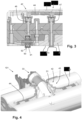
- Figures 2-6 serve to illustrate aspects of a wet cleaning nozzle 101 according to an embodiment of the invention, especially aspects of the wetting arrangement 42 of the wet cleaning nozzle 101.
- the conduit system 43 of the wetting arrangement 42 comprises two main conduits 44, 45 that are located in different halves of the wet cleaning nozzle 101 as seen in a longitudinal direction l being the direction in which the rotation axes 21 of the brushes 20 extend, and that are couplable to the liquid supply mechanism 41.
- the conduit system 43 comprises four branch conduits 46, 47, 48, 49, namely, as seen from left to right in figure 2 , i) a branch conduit 46 that is coupled to a first one 44 of the main conduits 44, 45, that is configured to release liquid to one of the wheels 90, and that extends from the first one 44 of the main conduits 44, 45 to the wheel 90, ii) a branch conduit 47 that is also coupled to the first one 44 of the main conduits 44, 45, at a longitudinal position more or less between the wheel 90 and the outlet opening 31, that is configured to release liquid to a first area of the surface 10 to be cleaned, and that extends from the first one 44 of the main conduits 44, 45 to the surface 10, iii) a branch conduit 48 that is coupled to a second one 45 of the main conduits 44, 45, at a longitudinal position more or less between another wheel 90 and the outlet opening 31, that is configured to release liquid to a second area of the surface 10 to be cleaned, and that extends from the second one 45 of the main conduit
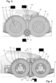
- FIG. 5 shows another advantageous yet non-essential aspect of the design of the wet cleaning nozzle 101 according to the embodiment of the invention, which resides in the fact that each of the two wheels 90 is arranged so as to be in contact with the brushes 20, especially with the microfiber elements 23 of the brushes 20.
- this measure contributes to keeping the wheels 90 clean.
- this measure contributes to realizing that the brushes 20 are wetted along their length, i.e. their dimension in the longitudinal direction l .
- the branch conduits 47, 48 that are configured to supply liquid to the surface 10 to be cleaned are arranged to partially extend through the elongated intermediate component 25.
- an end portion 47a, 48a of each of those branch conduits 47, 48 i.e. a portion including the end of the respective branch conduit 47, 48, protrudes relative to a bottom surface 26 of the wet cleaning nozzle 101 at the position of the elongated intermediate component 25, so that the positions P 1 , P 2 where the liquid is released to the surface 10 are at a distance from the bottom surface 26, and as a consequence, closer to the surface 10 than the bottom surface 26.
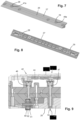
- a bottom cover 27 at a bottom side of the elongated intermediate component 25, and a possible design of such a bottom cover 27 is shown in figures 7 and 8 .
- components 28, 29 including the end portions 47a, 48a of the branch conduits 47, 48 arranged in the bottom cover 27.
- at least the end portions 47a, 48a are flexible, so that when the wet cleaning nozzle 101 is moved across a surface 10 and an obstacle is encountered, the end portions 47a, 48a flex, as a result of which damage to the end portions 47a, 48a and/or the obstacle is avoided and the shock from the impact on the obstacle is absorbed.
- the components 28, 29 may be provided as rubber components mounted in holes in the bottom cover 27.
- Figure 6 illustrates the advantageous concept of the wetting arrangement 42 being arranged and configured to release liquid to at least one area of the surface 10 to be cleaned at a liquid release position P 1 , P 2 that is at a relatively small distance to a surface interface level corresponding to a level of the lowest position of the wheels 90 of the wet cleaning nozzle 101, in other words, that is at a relatively small distance to a level of the surface 10 to be cleaned when the wet cleaning nozzle 101 is in an operational position on the surface 10.
- the relatively small distance is less than 2 mm. This implies that the end portions 47a, 48a of the branch conduits 47, 48 protrude towards the surface 10 so as to have their ends at a level of less than 2 mm above the surface 10.
- the bottom surface 26 of the wet cleaning nozzle 101 is at a higher level, wherein it is to be noted that for various reasons, it is advantageous if that higher level is still rather close to the level of the surface 10, wherein a maximum of 5 mm above the level of the surface 10 may be applicable, for example. Having only a small space between the surface 10 to be cleaned and the bottom surface 26 of the wet cleaning nozzle 101 contributes to cleanliness of the bottom surface 26 of the wet cleaning nozzle 101, which in turn contributes to achieving good cleaning results on the surface 10.
- the wheels 90 are examples of surface contacting elements that are arranged and configured to be in contact with the surface 10 to be cleaned through at least one contacting area, wherein the at least one contacting area on the surface contacting elements defines the surface interface level of the wet cleaning nozzle 101.
- the at least one contacting area is present at the lowest position of the wheel 90. This contacting area is indicated by reference numeral 92 in the relevant figures.
- the element 34 is flexible.
- the element 34 may comprise porous material so as to be very well capable of transporting liquid under the influence of capillary forces.
- the element 34 may be provided in any suitable form, wherein an option of the element 34 comprising a flexible wire composed of a number of fibres is mentioned as a practical example. Fibrous material has a relatively large surface and on the basis of narrow spaces between the fibres, adhesive and capillary forces are raised.
- the combined weight and stiffness of the element 34 is such that the free end of the element 34 is always pointing towards the surface 10 to be cleaned, eliminating or sufficiently reducing forces induced by movement of the wet cleaning nozzle 101 across the surface 10 and forces induced by the floating air during operation.
- the bottom surface 26 of the wet cleaning nozzle 101 that is at the relatively low level of less than 2 mm to the surface interface level, in which case the wetting arrangement 42 may be arranged and configured to release liquid at the position of a hole in the bottom surface 26. Also in such a case, it is practical to have flexibility at a bottom side of the wet cleaning nozzle 101. For example, assuming that the elongated intermediate component 25 is provided with a bottom cover 27 as suggested earlier, it may be so that the bottom cover 27 is flexible.
- the wetting arrangement 42 may be realized in any suitable way, as long as the wetting arrangement 42 is suitable to enable a supply of liquid to at least one area of the surface 10 to be cleaned.
- the wetting arrangement 42 is suitable to realize a supply of liquid to the at least one wheel 90
- FIG 10 a possible use of two squeegees 35, 36 in the wet cleaning nozzle 101 is illustrated.
- a practical arrangement of the two squeegees 35, 36 is an arrangement on the bottom cover 27 in which the squeegees 35, 36 extend along opposite sides of the bottom cover 27.
- the squeegees 35, 36 can create a scraping force on such a surface 10 which helps to remove certain substances from the surface 10 without having to increase energy consumption.
- the squeegees 35, 36 are provided with ribs or dots 37 on their interior surfaces so that a kind of one-way valve effect is obtained when the wet cleaning nozzle 101 is moved across the surface 10, such that clean liquid is allowed to pass the squeegee 35 at a back side while dirt is stopped from reaching the area between the squeegees 35, 36 at a front side.
- having the ribs or dots 37 also contributes to achieving good cleaning of the surface 10.
- a wet cleaning nozzle 101 is provided, which wet cleaning nozzle 101 comprises at least one surface contacting element 90 that is arranged and configured to be in contact with a surface 10 to be cleaned through at least one contacting area 92, wherein the at least one contacting area 92 on the at least one surface contacting element 90 defines a surface interface level of the wet cleaning nozzle 101.
- the wet cleaning nozzle 101 is further equipped with a wetting arrangement 42 that is arranged and configured to enable a supply of liquid to at least one area of the surface 10 to be cleaned by releasing liquid at a liquid release position P 1 , P 2 at a bottom side of the wet cleaning nozzle 101 that is configured to face the at least one area of the surface 10 to be cleaned, wherein the liquid release position P 1 , P 2 is at a level of less than 2 mm above the surface interface level. Having the relatively low level of the liquid release position P 1 , P 2 is a measure aimed at ensuring that the liquid that is let out of the wet cleaning nozzle 101 towards the surface 10 to be cleaned during operation actually ends up on the surface 10.
Landscapes
- Engineering & Computer Science (AREA)
- Mechanical Engineering (AREA)
- Nozzles For Electric Vacuum Cleaners (AREA)
Priority Applications (4)
| Application Number | Priority Date | Filing Date | Title |
|---|---|---|---|
| EP23151262.5A EP4400013A1 (fr) | 2023-01-12 | 2023-01-12 | Libération de liquide au niveau d'un côté inférieur d'une buse de nettoyage humide |
| PCT/EP2023/084955 WO2024149538A1 (fr) | 2023-01-12 | 2023-12-08 | Libération d'un liquide sur le côté inférieur d'une buse de nettoyage par voie humide |
| CN202380095724.6A CN121174974A (zh) | 2023-01-12 | 2023-12-08 | 在湿式清洁管嘴的底侧处释放液体 |
| EP23821283.1A EP4648658A1 (fr) | 2023-01-12 | 2023-12-08 | Libération d'un liquide sur le côté inférieur d'une buse de nettoyage par voie humide |
Applications Claiming Priority (1)
| Application Number | Priority Date | Filing Date | Title |
|---|---|---|---|
| EP23151262.5A EP4400013A1 (fr) | 2023-01-12 | 2023-01-12 | Libération de liquide au niveau d'un côté inférieur d'une buse de nettoyage humide |
Publications (1)
| Publication Number | Publication Date |
|---|---|
| EP4400013A1 true EP4400013A1 (fr) | 2024-07-17 |
Family
ID=84943084
Family Applications (2)
| Application Number | Title | Priority Date | Filing Date |
|---|---|---|---|
| EP23151262.5A Withdrawn EP4400013A1 (fr) | 2023-01-12 | 2023-01-12 | Libération de liquide au niveau d'un côté inférieur d'une buse de nettoyage humide |
| EP23821283.1A Pending EP4648658A1 (fr) | 2023-01-12 | 2023-12-08 | Libération d'un liquide sur le côté inférieur d'une buse de nettoyage par voie humide |
Family Applications After (1)
| Application Number | Title | Priority Date | Filing Date |
|---|---|---|---|
| EP23821283.1A Pending EP4648658A1 (fr) | 2023-01-12 | 2023-12-08 | Libération d'un liquide sur le côté inférieur d'une buse de nettoyage par voie humide |
Country Status (3)
| Country | Link |
|---|---|
| EP (2) | EP4400013A1 (fr) |
| CN (1) | CN121174974A (fr) |
| WO (1) | WO2024149538A1 (fr) |
Citations (2)
| Publication number | Priority date | Publication date | Assignee | Title |
|---|---|---|---|---|
| EP3366182A1 (fr) | 2017-02-27 | 2018-08-29 | Koninklijke Philips N.V. | Dispositif de nettoyage |
| EP4059398A1 (fr) * | 2021-03-17 | 2022-09-21 | Koninklijke Philips N.V. | Apport en liquide à au moins une roue d'une tête d'aspiration |
-
2023
- 2023-01-12 EP EP23151262.5A patent/EP4400013A1/fr not_active Withdrawn
- 2023-12-08 CN CN202380095724.6A patent/CN121174974A/zh active Pending
- 2023-12-08 EP EP23821283.1A patent/EP4648658A1/fr active Pending
- 2023-12-08 WO PCT/EP2023/084955 patent/WO2024149538A1/fr not_active Ceased
Patent Citations (3)
| Publication number | Priority date | Publication date | Assignee | Title |
|---|---|---|---|---|
| EP3366182A1 (fr) | 2017-02-27 | 2018-08-29 | Koninklijke Philips N.V. | Dispositif de nettoyage |
| EP4059398A1 (fr) * | 2021-03-17 | 2022-09-21 | Koninklijke Philips N.V. | Apport en liquide à au moins une roue d'une tête d'aspiration |
| WO2022194717A1 (fr) | 2021-03-17 | 2022-09-22 | Koninklijke Philips N.V. | Alimentation en liquide d'au moins une roue d'une tête d'aspiration |
Also Published As
| Publication number | Publication date |
|---|---|
| EP4648658A1 (fr) | 2025-11-19 |
| CN121174974A (zh) | 2025-12-19 |
| WO2024149538A1 (fr) | 2024-07-18 |
Similar Documents
| Publication | Publication Date | Title |
|---|---|---|
| US20220354330A1 (en) | Floor cleaning machine | |
| US6000088A (en) | Cordless wet mop and vacuum assembly | |
| US20090044351A1 (en) | Floor cleaning implement | |
| US20140041146A1 (en) | Floor cleaning tool having a mechanically operated pump | |
| EP0850589A1 (fr) | Assemblage de balai laveur et aspirateur sans fil | |
| EP4307976B1 (fr) | Apport en liquide à au moins une roue d'une tête d'aspiration | |
| US20240032763A1 (en) | Supplying liquid to at least one area of a surface to be cleaned | |
| CN119789805A (zh) | 具有储槽的地面清洁设备和用于运行地面清洁设备的方法 | |
| EP4400013A1 (fr) | Libération de liquide au niveau d'un côté inférieur d'une buse de nettoyage humide | |
| US9877624B2 (en) | Floor cleaning tool having a mechanically operated pump | |
| US20240156311A1 (en) | Suction head for application in a vacuum cleaner | |
| EP4516190A1 (fr) | Une buse de nettoyage humide comprenant deux brosses rotatives et un corps intermédiaire | |
| CN116172460A (zh) | 表面清洁机器 |
Legal Events
| Date | Code | Title | Description |
|---|---|---|---|
| PUAI | Public reference made under article 153(3) epc to a published international application that has entered the european phase |
Free format text: ORIGINAL CODE: 0009012 |
|
| STAA | Information on the status of an ep patent application or granted ep patent |
Free format text: STATUS: THE APPLICATION HAS BEEN PUBLISHED |
|
| AK | Designated contracting states |
Kind code of ref document: A1 Designated state(s): AL AT BE BG CH CY CZ DE DK EE ES FI FR GB GR HR HU IE IS IT LI LT LU LV MC ME MK MT NL NO PL PT RO RS SE SI SK SM TR |
|
| STAA | Information on the status of an ep patent application or granted ep patent |
Free format text: STATUS: THE APPLICATION IS DEEMED TO BE WITHDRAWN |
|
| 18D | Application deemed to be withdrawn |
Effective date: 20250118 |