EP4400143A2 - Ventilateur mécanique pour commander une source de gaz avec deux valves rotatives - Google Patents
Ventilateur mécanique pour commander une source de gaz avec deux valves rotatives Download PDFInfo
- Publication number
- EP4400143A2 EP4400143A2 EP24178314.1A EP24178314A EP4400143A2 EP 4400143 A2 EP4400143 A2 EP 4400143A2 EP 24178314 A EP24178314 A EP 24178314A EP 4400143 A2 EP4400143 A2 EP 4400143A2
- Authority
- EP
- European Patent Office
- Prior art keywords
- valve
- ventilator
- opening
- switching
- valve body
- Prior art date
- Legal status (The legal status is an assumption and is not a legal conclusion. Google has not performed a legal analysis and makes no representation as to the accuracy of the status listed.)
- Granted
Links
Images


Classifications
-
- A—HUMAN NECESSITIES
- A61—MEDICAL OR VETERINARY SCIENCE; HYGIENE
- A61M—DEVICES FOR INTRODUCING MEDIA INTO, OR ONTO, THE BODY; DEVICES FOR TRANSDUCING BODY MEDIA OR FOR TAKING MEDIA FROM THE BODY; DEVICES FOR PRODUCING OR ENDING SLEEP OR STUPOR
- A61M16/00—Devices for influencing the respiratory system of patients by gas treatment, e.g. ventilators; Tracheal tubes
- A61M16/0003—Accessories therefor, e.g. sensors, vibrators, negative pressure
- A61M16/0006—Accessories therefor, e.g. sensors, vibrators, negative pressure with means for creating vibrations in patients' airways
-
- A—HUMAN NECESSITIES
- A61—MEDICAL OR VETERINARY SCIENCE; HYGIENE
- A61M—DEVICES FOR INTRODUCING MEDIA INTO, OR ONTO, THE BODY; DEVICES FOR TRANSDUCING BODY MEDIA OR FOR TAKING MEDIA FROM THE BODY; DEVICES FOR PRODUCING OR ENDING SLEEP OR STUPOR
- A61M16/00—Devices for influencing the respiratory system of patients by gas treatment, e.g. ventilators; Tracheal tubes
- A61M16/0057—Pumps therefor
- A61M16/0066—Blowers or centrifugal pumps
- A61M16/0069—Blowers or centrifugal pumps the speed thereof being controlled by respiratory parameters, e.g. by inhalation
-
- A—HUMAN NECESSITIES
- A61—MEDICAL OR VETERINARY SCIENCE; HYGIENE
- A61M—DEVICES FOR INTRODUCING MEDIA INTO, OR ONTO, THE BODY; DEVICES FOR TRANSDUCING BODY MEDIA OR FOR TAKING MEDIA FROM THE BODY; DEVICES FOR PRODUCING OR ENDING SLEEP OR STUPOR
- A61M16/00—Devices for influencing the respiratory system of patients by gas treatment, e.g. ventilators; Tracheal tubes
- A61M16/021—Devices for influencing the respiratory system of patients by gas treatment, e.g. ventilators; Tracheal tubes operated by electrical means
- A61M16/022—Control means therefor
- A61M16/024—Control means therefor including calculation means, e.g. using a processor
-
- A—HUMAN NECESSITIES
- A61—MEDICAL OR VETERINARY SCIENCE; HYGIENE
- A61M—DEVICES FOR INTRODUCING MEDIA INTO, OR ONTO, THE BODY; DEVICES FOR TRANSDUCING BODY MEDIA OR FOR TAKING MEDIA FROM THE BODY; DEVICES FOR PRODUCING OR ENDING SLEEP OR STUPOR
- A61M16/00—Devices for influencing the respiratory system of patients by gas treatment, e.g. ventilators; Tracheal tubes
- A61M16/20—Valves specially adapted to medical respiratory devices
- A61M16/201—Controlled valves
- A61M16/202—Controlled valves electrically actuated
- A61M16/203—Proportional
- A61M16/204—Proportional used for inhalation control
-
- A—HUMAN NECESSITIES
- A61—MEDICAL OR VETERINARY SCIENCE; HYGIENE
- A61M—DEVICES FOR INTRODUCING MEDIA INTO, OR ONTO, THE BODY; DEVICES FOR TRANSDUCING BODY MEDIA OR FOR TAKING MEDIA FROM THE BODY; DEVICES FOR PRODUCING OR ENDING SLEEP OR STUPOR
- A61M16/00—Devices for influencing the respiratory system of patients by gas treatment, e.g. ventilators; Tracheal tubes
- A61M16/20—Valves specially adapted to medical respiratory devices
- A61M16/201—Controlled valves
- A61M16/202—Controlled valves electrically actuated
- A61M16/203—Proportional
- A61M16/205—Proportional used for exhalation control
-
- A—HUMAN NECESSITIES
- A61—MEDICAL OR VETERINARY SCIENCE; HYGIENE
- A61M—DEVICES FOR INTRODUCING MEDIA INTO, OR ONTO, THE BODY; DEVICES FOR TRANSDUCING BODY MEDIA OR FOR TAKING MEDIA FROM THE BODY; DEVICES FOR PRODUCING OR ENDING SLEEP OR STUPOR
- A61M16/00—Devices for influencing the respiratory system of patients by gas treatment, e.g. ventilators; Tracheal tubes
- A61M16/0003—Accessories therefor, e.g. sensors, vibrators, negative pressure
- A61M16/0009—Accessories therefor, e.g. sensors, vibrators, negative pressure with sub-atmospheric pressure, e.g. during expiration
-
- A—HUMAN NECESSITIES
- A61—MEDICAL OR VETERINARY SCIENCE; HYGIENE
- A61M—DEVICES FOR INTRODUCING MEDIA INTO, OR ONTO, THE BODY; DEVICES FOR TRANSDUCING BODY MEDIA OR FOR TAKING MEDIA FROM THE BODY; DEVICES FOR PRODUCING OR ENDING SLEEP OR STUPOR
- A61M16/00—Devices for influencing the respiratory system of patients by gas treatment, e.g. ventilators; Tracheal tubes
- A61M16/0096—High frequency jet ventilation
-
- A—HUMAN NECESSITIES
- A61—MEDICAL OR VETERINARY SCIENCE; HYGIENE
- A61M—DEVICES FOR INTRODUCING MEDIA INTO, OR ONTO, THE BODY; DEVICES FOR TRANSDUCING BODY MEDIA OR FOR TAKING MEDIA FROM THE BODY; DEVICES FOR PRODUCING OR ENDING SLEEP OR STUPOR
- A61M16/00—Devices for influencing the respiratory system of patients by gas treatment, e.g. ventilators; Tracheal tubes
- A61M16/10—Preparation of respiratory gases or vapours
- A61M16/105—Filters
- A61M16/1055—Filters bacterial
-
- A—HUMAN NECESSITIES
- A61—MEDICAL OR VETERINARY SCIENCE; HYGIENE
- A61M—DEVICES FOR INTRODUCING MEDIA INTO, OR ONTO, THE BODY; DEVICES FOR TRANSDUCING BODY MEDIA OR FOR TAKING MEDIA FROM THE BODY; DEVICES FOR PRODUCING OR ENDING SLEEP OR STUPOR
- A61M2205/00—General characteristics of the apparatus
- A61M2205/33—Controlling, regulating or measuring
- A61M2205/3365—Rotational speed
-
- A—HUMAN NECESSITIES
- A61—MEDICAL OR VETERINARY SCIENCE; HYGIENE
- A61M—DEVICES FOR INTRODUCING MEDIA INTO, OR ONTO, THE BODY; DEVICES FOR TRANSDUCING BODY MEDIA OR FOR TAKING MEDIA FROM THE BODY; DEVICES FOR PRODUCING OR ENDING SLEEP OR STUPOR
- A61M2205/00—General characteristics of the apparatus
- A61M2205/35—Communication
- A61M2205/3546—Range
- A61M2205/3553—Range remote, e.g. between patient's home and doctor's office
-
- A—HUMAN NECESSITIES
- A61—MEDICAL OR VETERINARY SCIENCE; HYGIENE
- A61M—DEVICES FOR INTRODUCING MEDIA INTO, OR ONTO, THE BODY; DEVICES FOR TRANSDUCING BODY MEDIA OR FOR TAKING MEDIA FROM THE BODY; DEVICES FOR PRODUCING OR ENDING SLEEP OR STUPOR
- A61M2205/00—General characteristics of the apparatus
- A61M2205/35—Communication
- A61M2205/3546—Range
- A61M2205/3561—Range local, e.g. within room or hospital
-
- A—HUMAN NECESSITIES
- A61—MEDICAL OR VETERINARY SCIENCE; HYGIENE
- A61M—DEVICES FOR INTRODUCING MEDIA INTO, OR ONTO, THE BODY; DEVICES FOR TRANSDUCING BODY MEDIA OR FOR TAKING MEDIA FROM THE BODY; DEVICES FOR PRODUCING OR ENDING SLEEP OR STUPOR
- A61M2205/00—General characteristics of the apparatus
- A61M2205/35—Communication
- A61M2205/3576—Communication with non implanted data transmission devices, e.g. using external transmitter or receiver
- A61M2205/3592—Communication with non implanted data transmission devices, e.g. using external transmitter or receiver using telemetric means, e.g. radio or optical transmission
Definitions
- Ventilators are used for the treatment of respiratory disorders. Ventilators can be used in non-invasive and invasive ventilation and in respiratory therapy, both in-hospital and out-of-hospital.
- the object of the invention is to provide an improved ventilator and a corresponding method which can be used for the treatment of respiratory disorders in non-invasive and invasive ventilation and in respiratory therapy and cough support, both in-hospital and out-of-hospital.
- the invention relates to a ventilator with a gas source (for example a blower), at least one gas line and a patient line and at least two valves, wherein each of the valves has at least indirectly a connection to the ambient air and wherein the valves are arranged in the gas line or as part of the gas line.
- a gas source for example a blower
- each of the valves has at least indirectly a connection to the ambient air and wherein the valves are arranged in the gas line or as part of the gas line.
- the gas line can comprise at least partial regions of a fan and/or at least one valve or valve body.
- the gas source can be a compressed gas line, a compressed gas source and/or a valve arrangement or an electrically operated blower.
- the invention additionally or alternatively relates to a ventilator in which the valves are at least temporarily connected in a gas-conducting manner to the gas source and the patient line or the ambient air.
- the invention also relates to a ventilator in which the two valves are connected in series in terms of flow in at least one switching position and in at least one part of the gas line.
- the invention also relates to a ventilator which is characterized in that one of the valves (switching valve) has a switching effect in such a way that in a first switching position an insufflation of the patient and in a second switching position an exsufflation of the patient are provided.
- An advantageous embodiment of the invention provides that one of the valves (oscillation valve) acts in such a way that by gradually opening and closing this valve, the flow resistance in the gas line between gas source and patient can be varied in such a way that oscillations of flow and pressure are caused during insufflation and/or exsufflation.
- a further advantageous embodiment of the invention provides that at least one control unit is set up and designed to control the gas source and/or to control the switching valve and/or to control the oscillation valve.
- control unit is set up and designed to control the blower and/or to control the switching valve and/or to control the oscillation valve, wherein a correspondingly high pressure is specified for the insufflation by the blower for a defined time and then the switching valve and/or the blower switches to the exsufflation, for which purpose the pressure is reduced to a correspondingly negative level within a defined time period and is held for a certain duration, wherein the pressure is then raised again to the desired level for the insufflation, wherein the switching is carried out in particular by the switching valve and/or the blower.
- the invention additionally also provides that the control unit is set up and designed to control the blower and/or to control the switching valve and/or to control the oscillation valve, wherein a correspondingly high pressure is specified for insufflation by the blower for a defined time and then the switching valve and/or the blower switches to exsufflation, for which purpose the pressure is reduced to a correspondingly negative level within a defined time period and is maintained for a certain duration, wherein the blower then increases the pressure again to the desired level for the break, wherein the pressure during the break has a slight overpressure, which is in particular between 2 and 15 mbar.
- control unit is set up and designed to control the blower and/or to control the switching valve and/or to control the oscillation valve, wherein the drop in pressure during the transition from insufflation to exsufflation occurs by a corresponding switching of the switching valve, so that a gas flow occurs from the patient line via the suction side of the blower to the environment 1.
- control unit is set up and designed to control the blower and/or to control the switching valve and/or to control the oscillation valve, wherein the increase in pressure from the exsufflation to the next insufflation or after a pause to the following insufflation preferably takes place less quickly or over a longer period of time, wherein the pressure increase takes place not only by changing the valve position of the switching valve but also by a corresponding increase in speed of the blower.
- control unit is set up and designed to control the blower and/or to control the switching valve and/or to control the oscillation valve, whereby a defined oscillation takes place at the pressure level of inspiration 30 or that of expiration or in the switching phase between inspiration 30 and expiration or during the pause, whereby the oscillation valve 3 acts in such a way that by gradually opening and closing this valve, the flow resistance in the gas line between blower and patient can be varied in such a way that oscillations of flow and/or pressure.
- control unit is set up and designed to control the blower and/or to control the switching valve and/or to control the oscillation valve, wherein for a coughing maneuver the switching valve is brought into the valve position for insufflation and then the speed of the blower is increased, whereby the pressure increases accordingly, wherein after reaching the pressure required for insufflation the speed is maintained and for switching to exsufflation the switching valve is switched into the valve position for exsufflation, whereby the pressure drops accordingly over a short period of time and thus the negative pressure required for exsufflation is achieved and the pressure and/or the speed of the blower for exsufflation are maintained for a predetermined time.
- a supplementary embodiment of the invention provides that at least one of the valves is designed as a rotatably mounted valve (rotary valve).
- a still further advantageous embodiment of the invention provides that at least one of the valves is designed as an axial valve, wherein an axial or linear movement guide for an opening or closing process is characteristic for an axial valve.
- a further advantageous embodiment of the invention provides that the switching valve has an electrically driven motor with a stator and a valve body which is fixedly attached to the rotor in a rotationally fixed manner, wherein the valve body is mounted so as to be rotatable about an axis of rotation and a radial and an axial direction of the valve body are defined on the basis of the axis of rotation.
- a further or additional advantageous embodiment of the invention provides that the oscillation valve has an electrically driven motor with a stator and a valve body which is fixedly attached to the rotor in a rotationally fixed manner, wherein the valve body is mounted so as to be rotatable about an axis of rotation and a radial and an axial direction of the valve body are defined on the basis of the axis of rotation.
- an alternative or additional advantageous embodiment of the invention provides that the oscillation valve is designed as a rotatably mounted valve and the valve body has at least one opening in the radial direction and at least one opening in the axial direction.
- An opening in the sense of the invention is a breakthrough or a recess in the valve or a partial area that allows a gas flow at least temporarily.
- the opening can also be created between two components that work together functionally in such a way that they at least temporarily open up an opening for a gas flow.
- An opening is designed according to the invention when a gas flow through the opening or along the opening is possible at least temporarily.
- a further alternative or additional advantageous embodiment of the invention provides that the opening points in the axial direction towards the connection which leads to the ambient air.
- valve body has a central region which extends cylindrically in the axial direction around the receptacle for the motor shaft, and the valve body also has a cover plate which extends in the radial direction starting from the upper end of the central region and on the radial outer edge or near the outer edge of the cover plate a wall region which extends in the axial direction or at a right angle starting from the cover plate and essentially parallel to the central region, wherein a channel which carries gas extends between the wall region and the central region and the openings are connected in a gas-conducting manner via the channel.
- the cover plate has an opening which, in a rotational position of the valve, is connected to the connection to the environment in a gas-conducting manner.
- the shape of the opening and/or the shape of the connection are designed such that the overlap between the opening and the connection increases or decreases linearly when the valve rotates, depending on the direction of rotation.
- a further advantageous embodiment of the invention provides that the blower, which has a suction side and a pressure side, with at least one control unit, wherein the pressure side is connected in a gas-conducting manner to a switching valve and connected to an oscillation valve, wherein the suction side is connected to the switching valve and the oscillation valve, wherein the switching valve has a connection to the suction side and a connection to the pressure side and a connection to the ambient air, and wherein the oscillation valve has a connection to the patient line and a connection to the pressure side and a connection to the ambient air.
- the invention provides that the switching valve and the oscillation valve are arranged in series between the blower and the patient line, wherein the connection to the patient line of the switching valve leads to the connection to the pressure side of the oscillation valve and the switching valve is thus indirectly connected to the patient line and the oscillation valve is indirectly connected to the pressure side.
- control unit is set up and designed to control the fan and/or to control the switching valve and/or to control the oscillation valve.
- the invention provides that the switching valve and the oscillation valve have a common control unit or separate control units, whereby alternatively or additionally these control units communicate with the control unit that controls the fan. It is also provided that only one control unit controls the fan, the switching valve and the oscillation valve.
- the fan, the switching valve and the oscillation valve can also each have a control unit, all of which are coordinated and controlled by a central control unit.
- the invention provides that the switching valve has switching means which are designed as a motor, as stops and as a valve body in a valve housing.
- the invention provides that the stops are formed in the valve housing.
- the invention provides that the motor rotates the valve body between at least three switching states, wherein the maximum rotation between the stops is a maximum of 150°, preferably a maximum of 120°, particularly preferably a maximum of 100°.
- the invention provides that the switching states for the switching valve are inhalation, exhalation and pause, wherein for inhalation the position of the valve body releases a gas flow from the environment to the suction side of the blower and at the same time enables a gas flow from the pressure side via the connection to the connection of the second valve.
- the invention provides that the switching states for the switching valve are inhalation, exhalation and pause, wherein for exhalation the position of the valve body releases a gas flow from the connection of the second valve via the connection to the suction side of the blower and a gas flow from the pressure side to the environment.
- the invention provides that the switching states for the switching valve are inhalation, exhalation and pause, wherein for the pause the position of the valve body releases a gas flow from the suction side of the blower to the pressure side, whereby the gas flow in at least one of the two directions from the environment to the patient or from the patient to the environment is essentially prevented.
- the invention provides that the oscillation valve is designed as a rotary valve and is equipped with a rotary valve body with a motor and with openings in several levels in a valve housing.
- the invention provides that the motor is a stepper motor.
- the invention provides that the stops are formed on the valve housing.
- the invention provides that the rotary valve body has openings which point in the radial direction and in the axial direction.
- the invention provides that the opening to the ambient air is arranged axially in the cover disk of the rotary valve body and a rotation of the rotary valve body brings the opening into overlap with the connection 36 to the ambient air.
- the invention provides that the openings are arranged radially in the rotary valve body and, in the corresponding switching position of the rotary valve body, enable a gas flow from the pressure side via the connection of the switching valve to the connection of the second valve and further via the connection to the patient line.
- the invention provides that in a pause switching state, a rotation of the rotary valve body releases the opening with the opening to the environment and enables a gas flow or a pressure reduction into the environment and the patient line is directly connected to the environment, bypassing the switching valve.
- a supplementary advantageous embodiment of the invention provides that in a switching state oscillation an oscillating movement of the valve body of the oscillation valve is provided with a certain frequency, which opens the opening to the environment and closes it again, which causes a temporary, frequency-dependent gas flow or pressure reduction into the environment, whereby the gas flow in at least one of the directions toward or away from the patient is superimposed with pressure and flow oscillations.
- an alternative advantageous embodiment of the invention provides that the oscillating movement is a rotary movement of the rotatably mounted valve body of an oscillation valve.
- Another advantageous embodiment of the invention provides that the oscillating movement is an axial movement of an axially mounted valve body of an oscillation valve.
- a further advantageous embodiment of the invention provides that the stops are designed to be hard.
- rotary encoders or light barriers can also be used.
- the opening in the oscillation valve allows the patient to be relieved quickly and does not have to breathe through the blower.
- the oscillation valve must rotate a maximum of 90° to enable oscillation; the movements for the motor are small.
- Asymmetric patterns of pressure or flow oscillation can be quickly created by moving the oscillation valve back and forth.
- valves can be manufactured with a lower mass inertia than valves that are intended to fulfill both functions in one; these would typically have to be made larger. This results in dynamic advantages during switching processes and/or oscillations. Tolerance considerations are less critical because the valve bodies are less complex.
- a clear allocation of the different functions of switching for coughing maneuvers and oscillation during the different phases of a coughing maneuver can be distributed between the two valves.
- the control of the valves can be developed and optimized separately and does not have to be carried out for a valve with a more complex overall function.
- linear drives are considered as one type of drive for the valves, whereby stepper motors for rotary valves, for example, bring cost advantages as inexpensive mass-produced goods.
- Driving the valves to stops enables the valve position to be detected without additional sensors. This can be done, for example, during certain calibration maneuvers at the end of service procedures or after each device start.
- the oscillation can be precisely adjusted depending on the shape of the opening.
- the user can set oscillations with different amplitudes, which are achieved by varying the angle of rotation of the oscillation valve during oscillation.
- the oscillation can be used in devices for mechanical ventilation and in devices for cough assistance. According to the invention, all of these devices and also other devices for respiratory therapy or ventilation are referred to simply as ventilators.
- the ventilator has at least one data transmission interface, which is designed and set up to transmit the content of the frequency counter stored in the memory unit with regard to coughing events to a data receiver or a data receiving unit.
- the data transmission can be wired or wireless.
- Data transmission interfaces can be, for example, an electronic data transmission bus, a network interface (e.g. LAN), a data transmission modem, a USB interface, a radio transmission interface such as infrared, Bluetooth, WIFI, GSM/LTE and the like or also a removable storage medium such as a memory card (flash), a USB stick/hard drive and the like.
- the data receiver or the data receiving unit can be, for example, a device-external (remote) data processing device with an evaluation unit (e.g. evaluation software), an expert user (e.g. doctor), a display device (e.g. display, monitor) and
- the data receiving unit can thus enable the analysis result to be assessed at a later point in time, particularly in the case where the ventilator does not have an internal evaluation unit.
- the ventilator can alternatively or additionally have an internal evaluation unit.
- the ventilator has a further sensor unit which is designed to detect a rotational speed of a ventilation fan and/or a leakage loss of the respiratory gas during ventilation of the person and/or a breath type such as spontaneous breathing or mandatory breathing and to feed it to the breath analyzer.
- the ventilator has an evaluation unit that is designed and configured to evaluate the analysis result of the analyzer with regard to cough-like complications of the ventilated person and to store it in the storage unit and/or display it on a display device and/or transmit it to a data receiving unit external to the device.
- the data can be transmitted in particular via the aforementioned data transmission interface.
- a data receiving unit is understood to be in particular a monitoring unit, a monitor in a hospital or nursing home and, in the case of home ventilation, a telemonitoring server. If the frequency and/or severity of a detected complication exceeds a specified limit, the ventilator can also be designed to issue an alarm, for example on the display device and/or to send an alarm to the data receiving unit.
- inhalation insufflation
- inspiration is used as synonyms in this application, as are the corresponding terms for exhalation, exsufflation, expiration.
- the Figure 1 shows a ventilator 1 according to the invention.
- the ventilator 1 can be designed as a ventilator for home or clinical applications and/or as a cough therapy device and/or as a combined ventilator and cough therapy device.
- the ventilator 1 is equipped with a blower device 10 or a fan to generate a breathing air flow for ventilating the patient.
- the ventilator 1 can additionally comprise at least one valve 2, 3.
- the ventilator 1 comprises, for example, at least one blower 10 and additionally at least one valve 2, 3 with which a breathing air flow for inhalation and a breathing air flow for exhalation are generated or modulated.
- the ventilator 1 alternatively comprises, for example, two blowers and at least one valve with which a breathing air flow for inhalation and a breathing air flow for exhalation are generated or modulated.
- the blower and/or the valve are optionally additionally designed and configured to superimpose a breathing air flow for inhalation and a breathing air flow for exhalation with a defined oscillation.
- the blower and/or the valve are optionally additionally designed and configured to generate or at least support the flow of breathing air for exhalation through negative pressure.
- Negative pressure means that the pressure generated by the ventilator is below the atmospheric pressure level.
- a breathing tube system 104 - 107 can be connected via a connection device 111, 109.
- the connection device is part of the patient line 14.
- the ventilator here includes, for example, a nebulizer device 110 in order to For example, to nebulize medication in the breathing air or a humidifier 110.
- the ventilator also serves to specifically support the removal of secretions from the airways of a patient and comprises at least one blower 10 and one valve 2,3.
- the hose system comprises a patient interface, which can be a mask or a mouthpiece, for example.
- a patient filter or bacterial filter is optionally used, which protects the hose system and/or ventilator from contamination with germs during the coughing or rebreathing phases.
- the hose system can also optionally be equipped with an exhalation system or a switchable patient valve, whereby in the simplest embodiment there are no other accessories in the hose system apart from the patient interface and optional filter.
- CO2-rich exhaled air can be discharged continuously or intermittently via an exhalation system or patient valve.
- the discharge of exhaled air can also be specifically adapted to breathing phases or coughing phases.
- Exhaled air can also be discharged to the ambient air via the at least one valve via at least one connection 26, 36.
- the ventilator 1 also has a display device 103 and an operating device 102, 112 for making inputs and settings.
- the operating device 102 can be designed as a touchscreen and/or as a mechanical operating element 112.
- One or more control devices 4 are provided to control at least the blower and valve.
- the blower and valve or display can also have their own or separate control devices.
- the control device preferably stores or saves specifications for controlling the blower and valve. These specifications can be at least partially adjusted by the user or a supervisor.
- the control device 4 comprises, for example, at least one controller and/or other control components.
- the ventilator 1 has at least one interface 108. Via the interface, for example, several ventilators or a ventilator can be connected wirelessly and/or communicate via wire.
- the interface 108 is, for example, operatively connected to the control device 4.
- the ventilator has at least one interface that is designed and configured to transmit the content of the frequency counter stored in the memory unit with regard to coughing events to a data receiver or a data receiving unit.
- the data transmission can be wired or wireless.
- Data transmission interfaces can be, for example, an electronic data transmission bus, a network interface (e.g. LAN), a data transmission modem, a USB interface, a radio transmission interface such as infrared, Bluetooth, WIFI, GSM/LTE and the like or also a removable storage medium such as a memory card (flash), a USB stick/hard drive and the like.
- the data receiver or the data receiving unit can be, for example, a device-external (remote) data processing device with an evaluation unit (e.g. evaluation software), an expert user (e.g. doctor), a display device (e.g. display, monitor) and the like.
- the data receiving unit can thus enable the analysis result to be assessed at a later point in time, particularly in the case where the ventilator does not have an internal evaluation unit.
- the ventilator can alternatively or additionally have an internal evaluation unit.
- the ventilator 1 alternatively offers the possibility of coupling one or more external device components (humidifier, nebulizer, oxygen mixer ...) via the interface 108 and thus functionally expanding or replacing the ventilator 1.
- FIG. 2 shows:
- the ventilator 100 according to the invention has at least one blower 10, with a suction side 11 and a pressure side 12, and at least one control unit 4 and a gas line 13 which connects the pressure side 12 to a patient line 14 in a gas-conducting manner.
- the gas line 13 is connected to a switching valve 2 and an oscillation valve 3.
- a suction gas line 9 connects the suction side 11 of the blower to the switching valve 2.
- the switching valve 2 has a connection 24 to the suction side 11 and a connection 25 to the pressure side 12, a connection 26 to the ambient air 15 and a connection 27 to the patient line 14.
- the oscillation valve 3 has a connection 34 to the patient line 14 and a connection 35 to the switching valve 2 and a connection 36 to the ambient air 16.
- the switching valve 2 and the oscillation valve 3 are arranged in series between the blower 10 and the patient line 14. For example, both valves are arranged in a common valve block.
- the connection 27 of the switching valve 2 is connected to the connection 35 of the oscillation valve 3 via the gas line 13 and the connection 34 is connected to the patient line 14.
- the blower is thus indirectly connected to the patient line 14 via the switching valve 2 and the oscillation valve 3.
- the ventilator is set up and designed to produce an at least temporary gas flow between the environment 15 and the patient line 14, wherein the gas flow can occur in both directions at least in sections.
- the at least one control unit 4 is configured and designed to control the fan 10 and/or to control the switching valve 2 and/or to control the oscillation valve 3.
- the at least one control unit 4 can be arranged adjacent to the valves and the blower 10 or remote from them and connected to them via a data line.
- the at least one control unit 4 controls the switching states for the switching valve 2 and the oscillation valve 3, namely inhalation, exhalation and pause.
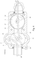
- FIG. 3 shows: The switching valve 2 and the oscillation valve 3 are arranged in series in the valve block 50, shown here in the upper half, between the environment 15 and the patient line 14.
- the gas line 13 connects the switching valve 2 and the oscillation valve 3 and is implemented in the valve block.
- the switching valve 2 has a connection 24 to the suction side 11 and a connection 25 to the pressure side 12 of the blower. Another connection leads to the ambient air 15 and a connection 27 via the gas line 13 to the oscillation valve 3 and to the patient line 14.
- the switching valve 2 is arranged in the valve housing 29, which here is a part of the valve block 50, and is connected to the motor shaft 28 via the valve body 23.
- the switching valve 2 has an electrically driven motor with a stator and a valve body 23 fastened to the rotor in a rotationally fixed manner.
- the motor has at least one winding through which current flows during operation.
- the valve body 23 is mounted so as to be rotatable about an axis of rotation.
- the axis of rotation defines a radial and an axial direction of the valve body 23.
- Two switching means point radially outwards from the valve body 23.
- the two switching means are designed as symmetrical valve surfaces 20.
- the valve housing 29 has a movement space for the switching means 20 and at least one stop 22 for the switching means.
- the stop is designed in such a way that it limits the movement of the valve so that the switching means hit the stop.
- the rotation is preferably limited to a range of 90 - 180 ° by two stops. Switching between inhalation and exhalation takes place using two switching states. A middle position is provided for the pause switching state.
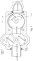
- FIG. 4 combined with Fig.2 and 3 shows:
- the switching valve 2 and the oscillation valve 3 are arranged in series in the valve block 50 between the environment 15 and the patient line 14.
- the gas line connects the switching valve 2 and the oscillation valve 3 and is implemented in the valve block.
- the switching valve 2 is arranged in the valve housing, which here is a portion of the valve block, and is connected to the motor shaft via the valve body 23.
- the switching valve 2 has an electrically driven motor with a stator and a valve body 23 fixed to the rotor in a rotationally fixed manner.
- the motor has at least one winding through which current flows during operation.
- the valve body 23 is mounted so as to be rotatable about an axis of rotation. A radial and an axial direction of the valve body 23 is defined by the axis of rotation 60.
- Two switching means point radially outwards from the valve body 23.
- the two switching means are designed as valve surfaces.
- the valve housing has a movement space for the switching means 20 and at least one stop 22 for the switching means.
- the stop is designed in such a way that it limits the movement of the valve so that the switching means hit the stop.
- the rotation is preferably limited to a range of 90 - 180 ° by two stops 22. Switching between inhalation and exhalation takes place using two switching states. A middle position is provided for the pause switching state.
- the oscillation valve is preferably designed as a rotatably mounted valve and is arranged in the valve housing 39, which here is a portion of the valve block 50, and is connected to the motor shaft via the valve body 33.
- the oscillation valve 3 has a Connection to the patient line 14 and a connection to the switching valve 2 and a connection 36 to the ambient air.
- the switching means in this embodiment is a rotary valve body 33 with openings in two different planes and directions. The openings point both radially and axially. At least one stop 32 on the valve and/or the housing limits the rotation of the valve. Rotation by more than one full revolution is thus prevented.
- the oscillation valve 3 has an electrically driven motor with a stator and a valve body 33 that is attached to the rotor in a rotationally fixed manner.
- the motor has at least one winding through which current flows during operation.
- the valve body 33 is mounted so as to be rotatable about an axis of rotation.
- the axis of rotation defines a radial and an axial direction of the valve body 33.
- the oscillation valve and/or the valve body 33 has at least one opening that leads to the patient line and an opening that leads to the ambient air.
- the valve body 33 is designed such that, depending on the valve position, it at least partially closes or opens the opening to the patient line or the opening to the ambient air for a flow of respiratory gas.
- the opening in the axial direction points to the connection 36 which leads to the ambient air 16.
- the valve body 33 has a central region which extends cylindrically in the axial direction around the receptacle for the motor shaft.
- the valve body 33 also has a cover disk 37 which extends from the upper end of the central region in the radial direction 61.
- the cover plate 37 is not continuous and leaves at least one opening which extends in the axial direction.
- the shape of the opening 63 and/or the shape of the connection 36 is selected, for example, such that the overlap between the opening 63 and the connection 36 increases or decreases linearly when the valve rotates, depending on the direction of rotation.
- the overlap between the opening 63 and the connection 36 can also increase non-linearly when the valve rotates, for example quadratically or logarithmically or discontinuously.
- the shape of the opening 63 and/or the shape of the connection 36 is, for example, at least partially oval, rounded or triangular.
- the control unit 4 sets the position of the switching valve 2 and the oscillation valve 3 in such a way that a gas flow from the environment via the connections 26 and 24 to the suction side 11 of the blower is possible and at the same time a gas flow from the pressure side 12 via the connection 25 and 27 to the connection 35 of the oscillation valve 3 and through the connection 34 to the patient line 14.
- the switching valve 2 and the oscillation valve 3 are arranged in series in the valve block between the blower 10 and the patient line 14.
- Figure 5 combined with Fig.2 and 3 shows:
- the control unit 4 sets the position of the switching valve 2 and the oscillation valve 3 so that a gas flow is released from the patient line 14 via the connection 34 and the connection 35 of the oscillation valve 3 via the connection 27 and the connection 24 of the switching valve to the suction side 11 (P-) of the blower.
- the blower thus sucks in breathing gas from the patient line.
- the breathing gas flows through the valves 3 and 2 and the connection 26 and then exits into the ambient air 15.
- the valve body 23 uses its switching means to separate the negative pressure range (P-) of the gases sucked in (arrows), which flow from the patient line 14 through the valve 3 and reach the suction side of the blower through a part of the switching valve 2, from the positive pressure range (P+) of the gases which are accelerated by the blower and are led through a part of the switching valve 2 to the connection 26 and further to the ambient air 15. and a gas flow from the pressure side 12 to the connection 26 and further to the ambient air 15 is possible.
- P- negative pressure range
- P+ positive pressure range
- FIG. 6 combined with Fig.2 and 3 shows: Compared to the position of the switching valve 2 from the Fig.4 or Fig.5 it can be seen that the switching valve was moved for the pause in such a way that the switching means pointing radially outwards from the valve body 23 do not hit any of the stops 22. Rather, the switching means are in a position between two stops 22. This position of the switching means allows gas to flow freely from the suction side 11 of the blower 10 to the pressure side 12.
- the control unit 4 sets the position of the switching valve 2 and the oscillation valve 3 in such a way that a gas flow through the connection 25 to the connection 24 is free and thus a gas flow from the suction side 11 of the blower 10 to the pressure side 12 is free and a gas flow to the environment is at least partially prevented or is not actively conveyed by the blower. Because in this switching position a recirculation from the pressure side of the blower to the suction side of the blower, no gas flow is forced towards the oscillation valve or towards the patient or away from the oscillation valve or away from the patient. Rather, the switching valve is preferably designed in such a way that in the pause switching position it has a neutral effect on the patient's breathing and inhalation or exhalation by the patient is basically possible through the switching valve.
- the oscillation valve 3 has been switched in such a way that a gas flow from or to the switching valve is not possible.
- the patient can breathe freely through the oscillation valve to the environment, since the valve has been moved in such a way that the opening 63 is connected to the connection 36 to the ambient air in a gas-conducting manner and thus a gas flow between the patient and the environment is possible.
- the control unit 4 specifies the position of the switching valve 2 and the oscillation valve 3 such that a gas flow (arrows) is possible from the environment 15 via the connections 26 and 24 to the suction side 11 of the blower and at the same time a gas flow from the pressure side 12 via the connections 25 and 27 to the connection 35 of the oscillation valve 3 and through the connection 34 to the patient line 14.
- the control unit 4 specifies the position of the oscillation valve 3 such that the connection 36 is alternately connected to the environment and then not connected again (indicated by the double arrow).
- Figure 8 shows in conjunction with Fig. 2-5 and 7 :
- the control unit 4 sets the position of the switching valve 2 and the oscillation valve 3 in such a way that a gas flow from the patient line 14 via the connection 34 and the connection 35 of the rotary valve 3 via the connection 27 and the connection 24 of the switching valve to the suction side 11 of the blower (P-) is released and a gas flow from the pressure side 12 (P+) to the environment 15 is possible.
- the control unit 4 sets the position of the oscillation valve 3 in such a way that the connection 36 is alternately connected to the environment and not connected again.
- FIG. 9 shows in conjunction with Fig.2-8 :
- the valve 2, 3 according to the invention is constructed here as a common valve block 50.
- the gas line 13 (not shown here), which connects the pressure side 12 of the blower to a patient line 14 in a gas-conducting manner, is implemented in the valve block.
- the gas line 13 is connected to a switching valve 2 and an oscillation valve 3.
- the switching valve 2 has a connection 24 to the suction side 11 and a connection 25 to the pressure side 12 of the blower (not shown), a connection 26 to the ambient air 15 and a connection 27 to the patient line 14.
- the oscillation valve 3 has a connection 34 to the patient line 14 and a connection 35 to the switching valve 2 and a connection 36 to the ambient air 16.
- the switching valve 2 and the oscillation valve 3 are arranged in series in the valve block between the blower 10 and the patient line 14.
- the connection 27 of the switching valve 2 is connected via the gas line 13 to the connection 35 of the oscillation valve 3 and the connection 34 is connected to the patient line 14.
- the blower is therefore indirectly connected to the patient line 14 via the switching valve 2 and the oscillation valve 3.
- the valve block 50 has an upper half 51 and a lower half 52.
- the motor 31 of the oscillation valve is arranged in the area of the upper half 51.
- the motor 21 of the switching valve is arranged in the area of the lower half 52.
- the upper half 51 and the lower half 52 can be screwed, locked or glued together.
- the realization of the valve bodies of both valves in one valve housing again has advantages in terms of manufacturing costs and installation space.
- FIG. 10 shows: The valve body 23 is mounted so as to be rotatable about a rotation axis 60. Due to the rotation axis 60, a radial and an axial direction 61, 62 of the valve body 23 is defined.
- Two switching means 20 point radially outward from the valve body 23.
- the two switching means 20 are designed as symmetrical valve surfaces 20.
- the valve housing 29 has a movement space for the switching means 20 and at least one stop 22 for the switching means.
- the stop is designed in such a way that it limits the movement of the valve so that the switching means hit the stop.
- the rotation is preferably limited to a range of 90 - 180 ° by two stops. Switching between inhalation and exhalation is done using two switching states. A middle position is provided for the pause switching state.
- the oscillation valve is preferably designed as a rotatably mounted valve and is arranged in the valve housing 39, which here is a portion of the valve block 50, and is connected to the motor shaft 38 via the valve body 33.
- the oscillation valve 3 has a connection 34 to the patient line 14 and a connection 35 to the switching valve 2 and a connection 36 to the ambient air 16.
- the switching means is a rotary valve body 33 with openings 63, 64, 65 in two different planes and directions. The openings point both radially and axially. At least one stop 32 on the valve and/or the housing limits the rotation of the valve. Rotation by more than one full revolution is thus prevented.
- the oscillation valve has an electrically driven motor 21 with a stator and a valve body 33 that is fixedly attached to the rotor in a rotationally fixed manner.
- the motor has at least one winding through which current flows during operation.
- the valve body 33 is mounted so as to be rotatable about a rotation axis 60. Due to the rotation axis 60, a radial and an axial direction 61, 62 of the valve body 33 are defined.
- the oscillation valve and/or the valve body 33 has at least one opening that leads to the patient line and an opening 63 that leads to the ambient air, and the valve body 33 is designed such that, depending on the valve position, the opening that leads to the patient line or the opening 63 that leads to the ambient air at least partially closes or opens for a respiratory gas flow.
- the oscillation valve and/or the valve body 33 has at least one opening that leads to the patient line and a further opening that leads to the ambient air, and wherein the valve body 33 is designed such that, depending on the valve position, it at least partially closes or opens the opening that leads to the patient line or the opening that leads to the ambient air for a respiratory gas flow.
- the valve body 33 of the oscillation valve has a region 66 which represents the receptacle 38 for the motor shaft and also a wall region 68 which, in a rotational position of the valve, at least partially closes or opens the opening leading to the patient line or the opening leading to the ambient air for a respiratory gas flow and, depending on the rotational position of the valve, at least one opening 63, 64, 65 of the valve thus releases a respiratory gas flow in the direction of the patient line or a gas flow in the direction of the environment 16.
- the opening 63 in the axial direction 62 points to the connection 36 which leads to the ambient air 16.
- the oscillation valve and/or the valve body 33 has at least one opening 65, 64 in the radial direction 61 and at least one opening 63 in the axial direction 62.
- the opening 63 in the axial direction 62 points to the connection 36 which leads to the ambient air 16.
- the valve body 33 has a central region 66 which extends cylindrically in the axial direction 62 around the receptacle 38 for the motor shaft.
- the valve body 33 also has a cover disk 37 which extends from the upper end of the central region 66 in the radial direction 61.
- the valve body On the radial outer edge or near the outer edge of the cover plate 37, the valve body has a wall region 68 which extends in the axial direction 62 or at a right angle from the cover plate and essentially parallel to the central region 66. Between the wall region 68 and the central region 66 there extends a channel 69 which carries gas and extends at least between the openings 65, 64 and/or also communicates with the opening 63.
- the channel 69 thus has, for example, three openings 63, 64, 65 which point in the axial 62 and/or radial 61 direction.
- the cover disk 37 is not continuous and leaves at least one opening 63 which extends in the axial direction 62.
- the wall region 68 is not continuous and leaves at least two openings 65, 64 free, which extend in the radial direction 61.
- the at least one opening 65, 64 in the radial direction 61 can also be designed as a bore through the valve body. There are then two openings 65, 64 which are connected to one another by a channel 69.
- An opening can also be a wide-lumen area in the sense of the invention, which enables a high gas flow.
- the wall region can take on any shape that is suitable. to substantially prevent gas flow. The wall region can therefore occupy an area smaller than the area of the opening.
- the shape of the opening 63 and/or the shape of the connection 36 is selected, for example, such that the overlap between the opening 63 and the connection 36 increases or decreases linearly when the valve rotates, depending on the direction of rotation.
- the overlap between the opening 63 and the connection 36 can also increase non-linearly when the valve rotates, for example quadratically or logarithmically or discontinuously.
- the shape of the opening 63 and/or the shape of the connection 36 is, for example, at least partially oval, rounded or triangular.
- the oscillation valve enables an oscillation on the pressure signal by reducing the pressure via an opening 63 to the environment.
- the opening to the environment can also be used to relieve the patient.
- the opening to the environment can also support or facilitate the patient's breathing in the pause position.
- Valve positions other than those shown here may also be provided for oscillation during insufflation and/or exsufflation.
- the Figure 12 shows an example of a pressure curve as it can be provided when using the ventilator 1.
- the pressure 301 was plotted against time 302.
- a correspondingly high pressure 301 is present for a defined time.
- the system then switches to exsufflation 305 very quickly.
- the pressure 301 is reduced to a correspondingly negative level within a defined period of time and is maintained for a certain duration.
- the switchover is carried out in particular by the switching valve 2 and the blower.
- the pressure can be raised again to the desired level for insufflation.
- the switchover is also carried out here in particular by the switching valve 2 and the blower.
- the pressure is then reduced very quickly 301 again for exsufflation.
- This change between insufflation and exsufflation can be repeated for a desired period of time.
- the number of repetitions and/or the frequency of repetitions can be set by a User or supervisor can specify this.
- a pause 306 is provided after exsufflation 305. This offers the patient great relief, as the coughing process requires considerable physical exertion.
- the pressure course shown here shows a slight overpressure or a positive therapy pressure during the pause 306. Exhaling against such a slight, targeted overpressure is particularly useful for respiratory therapy.
- the overpressure can, for example, be designed as a constant positive pressure (CPAP).
- the pressure is between 4 and 30 mbar.
- a pressure in the range of about +/-70 mbar or even higher can be set.
- the flows during inhalation and exhalation typically result in considerably smaller flows than during inhalation or exsufflation.
- Ventilation may also be provided during the break.
- a pressure of up to about 50 mbar and especially between 10-35 mbar is provided for ventilation or inspiration.
- the drop in pressure 301 during the transition from insufflation to exsufflation preferably occurs here by a correspondingly rapid switching of the valve unit.
- the speed of the blower for the exsufflation is preferably adjusted accordingly before the switching process of the valve unit. According to the invention, however, this is not necessary.
- the increase in pressure 301 from exsufflation to the next insufflation or after a break to the next insufflation preferably occurs less quickly or over a longer period of time.
- the pressure increase can be achieved by changing the valve position or by carefully increasing the speed of the blower.
- the increase in pressure 301 in the flow line for the pause 306 is also achieved by a correspondingly slow increase in the speed of the fan.
- a defined oscillation can take place at the level of inspiration 304 or expiration 305 or in the switching phase between inspiration 304 and expiration 305 or during the pause 306.
- the oscillation valve 3 acts in such a way that by gradually opening and closing this valve, the flow resistance in the gas line between the gas source and the patient can be varied in such a way that oscillations of flow and/or pressure are caused.
- the Figure 13 shows an example of a coughing maneuver followed by a pause 306.
- the pressure 301 was plotted against time 302.
- a speed 307 of the fan was plotted against time 302 as an example and in a highly idealized manner.
- a speed 307 of the fan was plotted against time 302 as an example and in a highly idealized manner.
- the vertical, dashed lines indicate a switching of the valve position in a highly schematic manner.
- valve unit is moved to the valve position for insufflation.
- the speed 307 of the blower is slowly increased over a defined time.
- the pressure 301 increases accordingly. After the pressure 301 required for insufflation is reached, the speed 307 is maintained.
- the change from insufflation 304 to exsufflation 305 takes place.
- the valve unit is switched to the second valve position.
- the pressure 301 drops accordingly over a very short period of time.
- the negative pressure required for exsufflation 305 is achieved.
- the speed 307 was increased to the required level before switching on.
- the pressure 301 or the speed for exsufflation 305 are now maintained for a predetermined time.
- the valve unit is then switched over again. After switching on, the speed 307 is increased to such an extent that a correspondingly slight overpressure is present that is suitable for ventilation during the pause 306.
- the fan therefore accelerates during the pressure build-up or to generate the pressure curve.
- the speed can be increased again in order to achieve the pressure 301 required for the insufflation 304.
- the coughing maneuver can now begin again.
- the invention presented here offers the advantage of providing a cough machine that is particularly patient-friendly and at the same time effective.
- the invention also offers the advantage of enabling significantly improved ventilation. For example, particularly gentle support can be provided during ventilation to remove secretions by supporting the patient with a negative therapy pressure during an exhalation phase.
- the invention can be used particularly advantageously with a two-tube system.
- Ventilation can be carried out alone or in combination with cough or secretion therapy. For example, during cough or secretion therapy there is a break in which positive therapy pressure is used to relieve the patient. The patient can also be ventilated during the break.
Landscapes
- Health & Medical Sciences (AREA)
- Life Sciences & Earth Sciences (AREA)
- General Health & Medical Sciences (AREA)
- Engineering & Computer Science (AREA)
- Anesthesiology (AREA)
- Biomedical Technology (AREA)
- Heart & Thoracic Surgery (AREA)
- Pulmonology (AREA)
- Hematology (AREA)
- Animal Behavior & Ethology (AREA)
- Emergency Medicine (AREA)
- Public Health (AREA)
- Veterinary Medicine (AREA)
- Percussion Or Vibration Massage (AREA)
- Respiratory Apparatuses And Protective Means (AREA)
- Multiple-Way Valves (AREA)
- Ventilation (AREA)
Applications Claiming Priority (3)
| Application Number | Priority Date | Filing Date | Title |
|---|---|---|---|
| DE102019004642 | 2019-07-02 | ||
| PCT/EP2020/025296 WO2021008722A1 (fr) | 2019-07-02 | 2020-06-23 | Ventilateur mécanique et procédé pour commander une source de gaz et deux valves rotatives |
| EP20740539.0A EP3993862B1 (fr) | 2019-07-02 | 2020-06-23 | Ventilateur mécanique pour commander une source de gaz avec deux valves rotatives |
Related Parent Applications (1)
| Application Number | Title | Priority Date | Filing Date |
|---|---|---|---|
| EP20740539.0A Division EP3993862B1 (fr) | 2019-07-02 | 2020-06-23 | Ventilateur mécanique pour commander une source de gaz avec deux valves rotatives |
Publications (3)
| Publication Number | Publication Date |
|---|---|
| EP4400143A2 true EP4400143A2 (fr) | 2024-07-17 |
| EP4400143A3 EP4400143A3 (fr) | 2024-09-11 |
| EP4400143B1 EP4400143B1 (fr) | 2026-01-14 |
Family
ID=71620392
Family Applications (2)
| Application Number | Title | Priority Date | Filing Date |
|---|---|---|---|
| EP20740539.0A Active EP3993862B1 (fr) | 2019-07-02 | 2020-06-23 | Ventilateur mécanique pour commander une source de gaz avec deux valves rotatives |
| EP24178314.1A Active EP4400143B1 (fr) | 2019-07-02 | 2020-06-23 | Ventilateur mécanique pour commander une source de gaz avec deux valves rotatives |
Family Applications Before (1)
| Application Number | Title | Priority Date | Filing Date |
|---|---|---|---|
| EP20740539.0A Active EP3993862B1 (fr) | 2019-07-02 | 2020-06-23 | Ventilateur mécanique pour commander une source de gaz avec deux valves rotatives |
Country Status (5)
| Country | Link |
|---|---|
| US (1) | US12478758B2 (fr) |
| EP (2) | EP3993862B1 (fr) |
| CN (1) | CN114269414B (fr) |
| DE (1) | DE202020005701U1 (fr) |
| WO (1) | WO2021008722A1 (fr) |
Families Citing this family (3)
| Publication number | Priority date | Publication date | Assignee | Title |
|---|---|---|---|---|
| EP4115929A1 (fr) * | 2021-07-09 | 2023-01-11 | Physio-Assist | Dispositif hospitalier pour la stimulation de l'air trachéobronchique |
| US20250032734A1 (en) * | 2023-07-28 | 2025-01-30 | Ventec Life Systems, INC | Control schemes for mechanical cough |
| CN121059958A (zh) * | 2024-06-05 | 2025-12-05 | 律维施泰因医学技术股份有限公司 | 用于对患者在咳嗽时进行支持的咳嗽设备 |
Family Cites Families (12)
| Publication number | Priority date | Publication date | Assignee | Title |
|---|---|---|---|---|
| US2695036A (en) * | 1949-06-30 | 1954-11-23 | Kidde Mfg Co Inc | Valve |
| GB920618A (en) * | 1960-10-24 | 1963-03-13 | Yorkshire Imp Metals Ltd | Combined fluid flow control and bleed valve |
| JP2798256B2 (ja) * | 1988-11-11 | 1998-09-17 | 株式会社メトラン | 人工呼吸器における呼吸振動発生装置 |
| DE19643750C2 (de) * | 1996-10-23 | 2001-01-25 | Draegerwerk Ag | Ventil zum Einstellen des Durchflusses eines Strömungsmediums |
| GB2404866B (en) * | 2003-08-15 | 2008-02-27 | Shahar Hayek | Respiratory apparatus |
| US8342204B2 (en) * | 2006-12-28 | 2013-01-01 | Perkins Engines Company Limited | Rotary valve for use in an internal combustion engine |
| CN102655903B (zh) * | 2009-12-15 | 2016-03-30 | 皇家飞利浦电子股份有限公司 | 用于在高频通气期间支持自主或者非自主呼吸中的亚生理以及生理潮气量的系统和方法 |
| US8539952B2 (en) * | 2011-05-13 | 2013-09-24 | Hill-Rom Services Pte. Ltd. | Mechanical insufflation/exsufflation airway clearance apparatus |
| US9642976B2 (en) | 2011-11-07 | 2017-05-09 | Koninklijke Philips N.V. | Systems and methods for intra-pulmonary percussive ventilation integrated in a ventilator |
| BR112014030139A2 (pt) * | 2012-06-05 | 2017-06-27 | Koninklijke Philips Nv | sistema configurado para inexsuflar um indivíduo, e método para gerar uma forma de onda de pressão de inexsuflação para fornecimento a um indivíduo com um sistema de inexsuflação |
| US20160018009A1 (en) * | 2014-07-15 | 2016-01-21 | Hsu-Nan Liu | Plug valve with linear flow control and method for designing the same |
| WO2017144963A2 (fr) * | 2016-02-22 | 2017-08-31 | Trivikram | Appareil de soins respiratoires |
-
2020
- 2020-06-23 WO PCT/EP2020/025296 patent/WO2021008722A1/fr not_active Ceased
- 2020-06-23 DE DE202020005701.0U patent/DE202020005701U1/de active Active
- 2020-06-23 CN CN202080057648.6A patent/CN114269414B/zh active Active
- 2020-06-23 US US17/597,267 patent/US12478758B2/en active Active
- 2020-06-23 EP EP20740539.0A patent/EP3993862B1/fr active Active
- 2020-06-23 EP EP24178314.1A patent/EP4400143B1/fr active Active
Also Published As
| Publication number | Publication date |
|---|---|
| WO2021008722A1 (fr) | 2021-01-21 |
| US12478758B2 (en) | 2025-11-25 |
| EP3993862B1 (fr) | 2024-05-29 |
| CN114269414B (zh) | 2024-09-27 |
| EP4400143B1 (fr) | 2026-01-14 |
| EP4400143A3 (fr) | 2024-09-11 |
| CN114269414A (zh) | 2022-04-01 |
| DE202020005701U1 (de) | 2022-02-04 |
| EP3993862A1 (fr) | 2022-05-11 |
| US20220313941A1 (en) | 2022-10-06 |
Similar Documents
| Publication | Publication Date | Title |
|---|---|---|
| EP3479860B1 (fr) | Dispositif de thérapie respiratoire | |
| EP3993862B1 (fr) | Ventilateur mécanique pour commander une source de gaz avec deux valves rotatives | |
| DE69034178T2 (de) | Drucksystem Für Atmungswege | |
| DE102006045739B3 (de) | Vorrichtung mit einem Beatmungsgerät und einem Anfeuchter | |
| DE69930183T2 (de) | Anästhesiegerät | |
| DE3884868T2 (de) | Tragbares Beatmungsgerät. | |
| EP3423136B1 (fr) | Dispositif de ventilation d'un patient | |
| EP3164183A1 (fr) | Respirateur | |
| EP3156091B1 (fr) | Dispositif de surveillance d'une déconnexion | |
| EP3730174A1 (fr) | Système d'alimentation en gaz respiratoire et procédé | |
| DE102004036879B3 (de) | Verfahren zur Einstellung eines Anästhesie- oder Beatmungsgerätes | |
| EP3957347A1 (fr) | Respirateur pour l'oxygénothérapie à débit élevé | |
| DE102017005805A1 (de) | Beatmungsgerät und Verfahren | |
| WO2003002176A2 (fr) | Procede et dispositif d'alimentation en gaz respiratoire | |
| EP1586343B1 (fr) | Appareil respiratoire et méthode de commande d'un appareil respiratoire | |
| DE102023123866A1 (de) | Beatmungsvorrichtung und Verfahren zur Steuerung einer Beatmungsvorrichtung | |
| EP4285974A1 (fr) | Procédé de fonctionnement d'un appareil respiratoire | |
| DE102010045839A1 (de) | Verfahren und Vorrichtung zur Beatmung mit Hintergrundfrequenz | |
| DE102017005803A1 (de) | Beatmungsgerät und Verfahren | |
| EP4129376B1 (fr) | Dispositif de ventilation d'un patient à transition de pression régulée | |
| DE102024116894A1 (de) | Vorrichtung und Verfahren zum Erzeugen eines Vordruckes an einem Regelventil eines Beatmungsgerätes | |
| DE102007033048A1 (de) | Vorrichtung und Verfahren zur Verbesserung der Lungenbeschaffenheit | |
| DE102020109707A1 (de) | Mobiles Beatmungsgerät, insbesondere zur Verwendung bei der Behandlung von COVID-19 | |
| WO2019057641A1 (fr) | Dispositif de réglage d'une pression interne dans un corps creux d'étanchéité | |
| WO2025098550A1 (fr) | Système de ventilation |
Legal Events
| Date | Code | Title | Description |
|---|---|---|---|
| PUAI | Public reference made under article 153(3) epc to a published international application that has entered the european phase |
Free format text: ORIGINAL CODE: 0009012 |
|
| STAA | Information on the status of an ep patent application or granted ep patent |
Free format text: STATUS: REQUEST FOR EXAMINATION WAS MADE |
|
| 17P | Request for examination filed |
Effective date: 20240529 |
|
| AC | Divisional application: reference to earlier application |
Ref document number: 3993862 Country of ref document: EP Kind code of ref document: P |
|
| AK | Designated contracting states |
Kind code of ref document: A2 Designated state(s): AL AT BE BG CH CY CZ DE DK EE ES FI FR GB GR HR HU IE IS IT LI LT LU LV MC MK MT NL NO PL PT RO RS SE SI SK SM TR |
|
| REG | Reference to a national code |
Ref country code: DE Ref legal event code: R079 Free format text: PREVIOUS MAIN CLASS: A61M0016100000 Ipc: A61M0016200000 Ref document number: 502020012582 Country of ref document: DE |
|
| PUAL | Search report despatched |
Free format text: ORIGINAL CODE: 0009013 |
|
| P01 | Opt-out of the competence of the unified patent court (upc) registered |
Free format text: CASE NUMBER: APP_42248/2024 Effective date: 20240717 |
|
| AK | Designated contracting states |
Kind code of ref document: A3 Designated state(s): AL AT BE BG CH CY CZ DE DK EE ES FI FR GB GR HR HU IE IS IT LI LT LU LV MC MK MT NL NO PL PT RO RS SE SI SK SM TR |
|
| RIC1 | Information provided on ipc code assigned before grant |
Ipc: A61M 16/10 20060101ALN20240806BHEP Ipc: A61M 16/00 20060101ALI20240806BHEP Ipc: A61M 16/20 20060101AFI20240806BHEP |
|
| GRAP | Despatch of communication of intention to grant a patent |
Free format text: ORIGINAL CODE: EPIDOSNIGR1 |
|
| STAA | Information on the status of an ep patent application or granted ep patent |
Free format text: STATUS: GRANT OF PATENT IS INTENDED |
|
| RIC1 | Information provided on ipc code assigned before grant |
Ipc: A61M 16/20 20060101AFI20250716BHEP Ipc: A61M 16/00 20060101ALI20250716BHEP Ipc: A61M 16/10 20060101ALN20250716BHEP |
|
| RIC1 | Information provided on ipc code assigned before grant |
Ipc: A61M 16/20 20060101AFI20250725BHEP Ipc: A61M 16/00 20060101ALI20250725BHEP Ipc: A61M 16/10 20060101ALN20250725BHEP |
|
| INTG | Intention to grant announced |
Effective date: 20250804 |
|
| RIC1 | Information provided on ipc code assigned before grant |
Ipc: A61M 16/20 20060101AFI20250725BHEP Ipc: A61M 16/00 20060101ALI20250725BHEP Ipc: A61M 16/10 20060101ALN20250725BHEP |
|
| GRAS | Grant fee paid |
Free format text: ORIGINAL CODE: EPIDOSNIGR3 |
|
| GRAA | (expected) grant |
Free format text: ORIGINAL CODE: 0009210 |
|
| STAA | Information on the status of an ep patent application or granted ep patent |
Free format text: STATUS: THE PATENT HAS BEEN GRANTED |
|
| AC | Divisional application: reference to earlier application |
Ref document number: 3993862 Country of ref document: EP Kind code of ref document: P |
|
| AK | Designated contracting states |
Kind code of ref document: B1 Designated state(s): AL AT BE BG CH CY CZ DE DK EE ES FI FR GB GR HR HU IE IS IT LI LT LU LV MC MK MT NL NO PL PT RO RS SE SI SK SM TR |
|
| REG | Reference to a national code |
Ref country code: CH Ref legal event code: F10 Free format text: ST27 STATUS EVENT CODE: U-0-0-F10-F00 (AS PROVIDED BY THE NATIONAL OFFICE) Effective date: 20260114 Ref country code: GB Ref legal event code: FG4D Free format text: NOT ENGLISH |
|
| REG | Reference to a national code |
Ref country code: DE Ref legal event code: R096 Ref document number: 502020012582 Country of ref document: DE |
|
| REG | Reference to a national code |
Ref country code: IE Ref legal event code: FG4D Free format text: LANGUAGE OF EP DOCUMENT: GERMAN |
|
| REG | Reference to a national code |
Ref country code: NL Ref legal event code: FP |