EP4400182A1 - Vorrichtungen und verfahren zur messung der brandausbreitungsrate - Google Patents
Vorrichtungen und verfahren zur messung der brandausbreitungsrate Download PDFInfo
- Publication number
- EP4400182A1 EP4400182A1 EP23207434.4A EP23207434A EP4400182A1 EP 4400182 A1 EP4400182 A1 EP 4400182A1 EP 23207434 A EP23207434 A EP 23207434A EP 4400182 A1 EP4400182 A1 EP 4400182A1
- Authority
- EP
- European Patent Office
- Prior art keywords
- fire
- sensor
- location
- spread rate
- fire spread
- Prior art date
- Legal status (The legal status is an assumption and is not a legal conclusion. Google has not performed a legal analysis and makes no representation as to the accuracy of the status listed.)
- Pending
Links
Images


Classifications
-
- A—HUMAN NECESSITIES
- A62—LIFE-SAVING; FIRE-FIGHTING
- A62C—FIRE-FIGHTING
- A62C37/00—Control of fire-fighting equipment
- A62C37/36—Control of fire-fighting equipment an actuating signal being generated by a sensor separate from an outlet device
-
- A—HUMAN NECESSITIES
- A62—LIFE-SAVING; FIRE-FIGHTING
- A62C—FIRE-FIGHTING
- A62C37/00—Control of fire-fighting equipment
- A62C37/36—Control of fire-fighting equipment an actuating signal being generated by a sensor separate from an outlet device
- A62C37/38—Control of fire-fighting equipment an actuating signal being generated by a sensor separate from an outlet device by both sensor and actuator, e.g. valve, being in the danger zone
- A62C37/40—Control of fire-fighting equipment an actuating signal being generated by a sensor separate from an outlet device by both sensor and actuator, e.g. valve, being in the danger zone with electric connection between sensor and actuator
-
- G—PHYSICS
- G08—SIGNALLING
- G08B—SIGNALLING SYSTEMS, e.g. PERSONAL CALLING SYSTEMS; ORDER TELEGRAPHS; ALARM SYSTEMS
- G08B17/00—Fire alarms; Alarms responsive to explosion
- G08B17/12—Actuation by presence of radiation or particles, e.g. of infrared radiation or of ions
- G08B17/125—Actuation by presence of radiation or particles, e.g. of infrared radiation or of ions by using a video camera to detect fire or smoke
-
- A—HUMAN NECESSITIES
- A62—LIFE-SAVING; FIRE-FIGHTING
- A62C—FIRE-FIGHTING
- A62C3/00—Fire prevention, containment or extinguishing specially adapted for particular objects or places
- A62C3/06—Fire prevention, containment or extinguishing specially adapted for particular objects or places of highly inflammable material, e.g. light metals, petroleum products
Definitions
- Exemplary embodiments of the present disclosure relate generally to methods and apparatuses for measuring a fire spread rate, and more particularly, to methods and apparatuses for triggering an extinguisher system according to the fire spread rate.
- Fire sensors may be used to detect a fire and trigger an extinguishing system, and may be implemented in various applications.
- a fire sensor may be a part of a system for detecting a fire and triggering an extinguishing system.
- Such fire sensors are plagued by technical challenges and limitations. Through applied effort, ingenuity, and innovation, many of these identified problems have been solved by developing solutions that are included in embodiments of the present disclosure, many examples of which are described in detail herein.
- Various embodiments described herein relate to methods, apparatuses, and systems for configuring an apparatus, for example a method for measuring a fire spread rate.
- a method for measuring a fire spread rate by a controller component comprises: monitoring a field of view of a first sensor, where the first sensor is a long wavelength infrared (LWIR) camera configured to detect one or more fire by products; determining that a fire event occurs based on a detection of at least one particle in the field of view of the first sensor; determining a fire spread rate in an instance that the fire event occurs; and triggering an extinguisher system according to the fire spread rate and a distance between the first sensor and the extinguisher system.
- LWIR long wavelength infrared
- determining the fire spread rate comprises: determining a first time that the first sensor detects fire particles at a first location; determining a second time that the first sensor detects the fire particles at a second location; determining a distance between the first location and the second location; and calculating the fire spread rate according to the first time, the second time, and the distance between the first location and the second location.
- the LWIR camera includes a bandwidth filter configured to detect the one or more fire by products.
- the first location and the second location are located along an axis of a pipeline.
- the second location is further located in a line of sight of the first sensor; and the first location is angled ⁇ with respect to the line of sight of the first sensor.
- the pipeline is a cylindrical tube.
- the method for measuring the fire spread rate by the controller component further comprises monitoring a field of view of a second sensor, wherein the second sensor is also a LWIR camera configured to detect the one or more fire by products.
- determining the fire spread rate comprises: determining a second time when the first sensor detects fire particles; determining a third time when a second sensor detects the fire particles; determining a distance between the first sensor and the second sensor; and calculating the fire spread according to the second time, the third time, and the distance between the first sensor and the second sensor.
- the method for measuring the fire spread rate by the controller component further comprises determining that the fire event spreads by comparing the fire spread rate with a predetermined threshold spread rate. In some embodiments, determining whether a fire event occurs comprises: comparing a number of fire particle detected by the first sensor with a threshold.
- an apparatus for measuring a fire spread rate comprises: a fire spread rate measurement component, including a first sensor and an extinguisher system, wherein the first sensor is a long wavelength infrared (LWIR) camera configured to detect one or more fire by products; and a controller component electronically coupled to the fire spread rate measurement component, wherein the controller component is configured to: monitor a field of view of the first sensor; determine that a fire event occurs based on a detection of at least one particle in the field of view of the first sensor; determine a fire spread rate in an instance that the fire event occurs; and trigger the extinguisher system according to the fire spread rate and a distance between the first sensor and the extinguisher system.
- LWIR long wavelength infrared
- ком ⁇ онент or feature may,” “can,” “could,” “should,” “would,” “preferably,” “possibly,” “typically,” “optionally,” “for example,” “often,” or “might” (or other such language) be included or have a characteristic, that a specific component or feature is not required to be included or to have the characteristic. Such components or features may be optionally included in some embodiments, or may be excluded.
- electrostatically coupled or “in electronic communication with” in the present disclosure refer to two or more electrical elements (for example, but not limited to, a controller, sensors, an example processing circuitry, communication module, input/output module, memory) and/or electric circuit(s) being connected through wired means (for example but not limited to, conductive wires or traces) and/or wireless means (for example but not limited to, wireless network, electromagnetic field), such that data and/or information (for example, electronic indications, signals) may be transmitted to and/or received from the electrical elements and/or electric circuit(s) that are electronically coupled.
- electrical elements for example, but not limited to, a controller, sensors, an example processing circuitry, communication module, input/output module, memory
- electric circuit(s) being connected through wired means (for example but not limited to, conductive wires or traces) and/or wireless means (for example but not limited to, wireless network, electromagnetic field), such that data and/or information (for example, electronic indications, signals) may be transmitted to and/or received from the
- electromagnetic radiation may refer to various kinds of electromagnetic radiant energy that exhibits properties of waves and particles including visible light, radio waves, microwaves, infrared (IR), ultraviolet (UV), X-rays and gamma rays.
- Visible light may refer to electromagnetic radiation that can be detected by a human eye.
- the electromagnetic spectrum comprises a range of all known types of electromagnetic radiation, including electromagnetic radiation that cannot be detected by the human eye.
- Various portions of the electromagnetic spectrum are associated with electromagnetic radiation that has certain characteristics (e.g., certain wavelengths and frequencies).
- visible light emits electromagnetic radiation with wavelengths ranging between 380 and 750 nanometers (nm).
- IR electromagnetic radiation may comprise wavelengths ranging between 0.7 and 14 microns.
- the sensors may detect fire particles through the electromagnetic radiation of the fire particles.
- fire may also refer to combustion, smoldering, burning, excessive heat, and/or flame associated with or related to a state, process, or instance of combustion in which fuel or other material is ignited and combined with oxygen, giving off light, heat, and/or flame.
- fire produces electromagnetic radiation with certain characteristics.
- fire may emit electromagnetic radiation with particular visible and/or infrared light characteristics/properties (e.g., wavelengths, intensity, image shape, and/or the like). These characteristics and properties may depend on characteristics of a fire source (e.g., fuel type).
- the visible light radiation produced by a fire may be detected using visible wavelength camera(s), and/or the infrared radiation may be detected using infrared camera(s).
- An example method for determining a fire spread rate may comprise determining the fire spread rate in an instance when a fire event is detected.
- the example method for determining the fire spread rate may be implemented in environments where there is a high likelihood of a fire and/or where certain types of combustible materials are used or stored.
- the example method for determining the fire spread rate may be implemented at power plants, chemical storage and production facilities, factories, etc.
- the example method for determining the fire spread rate may be implemented in residential, commercial, recreational and/or other facilities.
- the example method for determining the fire spread rate may be implemented in any environment where fire may cause harm to life, health, and/or property.
- a sensor to detect a fire event may be configured to detect infrared radiation peak that may be produced by the carbon dioxide byproduct of fire at wavelengths about 2 to 6 micron, more preferably 3.5 to 5 micron, and most preferably about 4.3 micron.
- a sensor for detecting a fire event may be configured to detect, in some examples, an infrared radiation emitted by the water byproduct of a fire to detect the fire.
- the infrared radiation emitted by the water byproduct of fire in some examples, has a unique pattern/signature in the wavelength range of about 1 microns to about 14 microns.
- a sensor for detecting a fire event may use long wavelength infrared (LWIR) camera(s) with, in some examples, bandpass filters with passband between about 1 microns to about 14 microns.
- LWIR long wavelength infrared
- a controller component may be in electrical communication with the sensor and configured to determine the fire spread rate according to a signal collected from the sensor.
- the signal collected from the sensor may include a location of fire event and a time stamp of the fire event.
- a controller component may be in electrical communication with at least two sensors and configured to determine the fire spread rate according to signals collected from the at least two sensors.
- the controller component may further be configured to determine a distance between fixed positions along a physical structure, such as a pipeline. For example, the controller component may be configured to determine a distance between a first position and a second location.
- the first position and the second location are located on an axis of a pipeline.
- the controller component may be further configured to determine a fire spread rate according to time stamps to detect fire particles of the fire event at various positions, such as the first position and the second position (e.g., fixed positions).
- the controller component may be configured to determine a fire spread rate according to a first time to detect the fire particles of the fire event at the first position and a second time to detect the fire particles of the fire event at the second location.
- the controller component may be configured to trigger or activate an extinguisher system according to the fire spread rate only when it is needed, such that a waste of the suppression material of the extinguisher system may be avoided and the effective usage of the extinguisher system may be improved.
- the fire spread rate measurement apparatus 100 may include a fire spread rate measurement component 101 and a controller component 102 in electronic communication with the fire spread rate measurement component 101.
- the fire spread rate measurement component 101 may include a physical component, such as a pipeline 103.
- the pipeline 103 may be used to store, transfer, or move a fluid.
- the fluid may be natural gas and/or the like.
- the pipeline 103 may be made of steel tubes, plastic tubes, or the like.
- the pipeline 103 may be used as passage to heat, ventilate, and air condition to deliver and remove air.
- the pipeline 103 may be made of steel tubes, aluminum tube, plastic tubes, or the like.
- a first sensor 104 may be located or otherwise positioned along a wall of the pipeline 103.
- the first sensor 104 may be configured to receive or detect the fire particles radiated from the fire source 107 when the fire particles reach a field of view of the first sensor 104.
- the first sensor 107 may be a long wavelength infrared (LWIR) camera configured to detect one or more fire by products of the one or more fire.
- LWIR long wavelength infrared
- the first sensor 104 may be configured to detect infrared radiation peak that may be produced by the carbon dioxide byproduct of fire at wavelengths about 2 to 6 micron, more preferably 3.5 to 5 micron, and most preferably about 4.3 micron.
- water is also a byproduct of fire.
- the first sensor 104 may be configured to detect, in some examples, an infrared radiation emitted by the water byproduct of a fire to detect the fire.
- the infrared radiation emitted by the water byproduct of fire in some examples, has a unique pattern/signature in the wavelength range of about 7 microns to about 8 microns.
- a sensor for detecting a fire event may use long wavelength infrared (LWIR) camera(s) with, in some examples, bandpass filters with passband between about 7 microns to about 14 microns.
- LWIR long wavelength infrared
- the first sensor 104 may generate a first signal 120.
- the first signal 120 may include a plurality of time stamps indicating a time in which fire particles reach a particular location within the pipeline 103.
- the first signal 120 may include a first time indicating a time in which the fire particles reach a first location 110.
- the first location 110 may be angled ⁇ with respect to a line of sight 108 of the first sensor 104.
- the first signal may further include a second time indicating a time in which the fire particles reach a second location 111.
- the second location 111 may be in the line of sight 108 of the first sensor 104.
- the first sensor 104 may have an angle of view 20.
- the first sensor 104 may detect a maximum number of fire particles at the second location 111 when the second location 111 is in the line of sight 108 of the first sensor 104.
- the first sensor 104 may detect a minimum number of fire particles at the first location 110 when the first location 110 is angled ⁇ with respect to a line of sight 108 of the first sensor 104.
- the first location 110 may be angled 45° with respect to the line of sight 108 of the first sensor 104.
- the pipeline 103 may take a form of a cylindrical tube.
- the cylindrical tube used to transport natural gas may have an inner diameter D in a range from 10 mm to 2000 mm, preferable in a range from 100 mm to 1220 mm.
- the cylindrical tube used as air passages may have an inner diameter D in a range from 50 mm to 1000 mm, preferable in a range from 100 mm to 500 mm.
- the fire spread rate measurement component 101 may further include a second sensor 105 located along the wall of the pipeline 103.
- the second sensor 105 may be configured to receive or detect the fire particles radiated from the fire source 107 when the fire particles reach a third location 112.
- the second sensor 105 may generate a second signal 121.
- the second signal 121 may include a time stamp that provides an indication of when the fire particles reach or are otherwise detected within the field of view of the second sensor 105.
- the second signal 121 may include a third time indicating a time in which the fire particles reach a third location 112.
- a distance between the second location 111 and the third location 112 is L and the third location 112 may be in a line of sight of the second sensor 105.
- the controller component 102 may set or be otherwise be provided with a threshold number of fire particles for the first sensor 104 and the second sensor 105 according to the minimum number of fire particles at the first location 110 when the first location 110 is angled ⁇ with respect to a line of sight 108 of the first sensor 104.
- the threshold number of fire particles may be set to be equal to the minimum number of fire particles at the first location 110.
- the controller component 102 may determine a fire event is detected when the first sensor 104 or the second sensor 105 detects more fire particles than the threshold number of fire particles.
- the controller component 102 may set or be otherwise be provided with a threshold number of fire particles for the first sensor 104 and the second sensor 105 according to the number of fire particles at the second location 111, which is in a line of sight 108 of the first sensor 104.
- the threshold number of fire particles may vary according to different industry standard. For example, a weighted moving average of the number of fire particles may be used as the threshold number of fire particles.
- the controller component 102 may sample the first sensor 104 or the second sensor 105 once every 16 ms and determine a fire event occurs when the detected number of fire particles is greater than the threshold number of fire particles for a continuous ten 160 ms.
- the fire spread rate measurement component 101 may further include an extinguisher system 106 located further along the wall of the pipeline 103.
- the controller component 102 may generate a third signal 122 according to the fire spread rate of the fire and send the third signal to the extinguisher system 106.
- the extinguisher system 106 may receive the third signal 122 from the controller component 102.
- the third signal 122 may include an activation signal to activate the extinguisher system 106 to extinguish the fire particles.
- the third signal 122 may include the fire spread rate.
- the fire spread rate may be provided to fire officers through the extinguisher system 106.
- the extinguisher system 106 may include a plurality of fire extinguishers that can be triggered or activated to flood a space with an agent, such that the fire may be suppressed by the agent.
- the extinguishing system may produce a guess that removes oxygen from the area so as to extinguish the fire.
- the controller component 102 may determine when to activate the extinguisher system 106 according to a distance between the extinguisher system 106 and the first sensor 104.
- FIG. 1 provides an example fire spread rate measurement apparatus 100 that includes a first sensor 104 and a second sensor 105
- the example fire spread rate measurement apparatus 100 may include only the first sensor 104.
- the example fire spread rate measurement apparatus 100 may include one or more sensor(s) in addition to the first sensor 104 and the second sensor 105.
- the example fire spread rate measurement apparatus 100 may include one or more additional and/or alternative elements, and/or may be structured/positioned differently than that illustrated in FIG. 1 .
- the fire spread rate measurement apparatus 100 may include more than two sensor(s) that may receive and/or detect the fire particles emitted by the fire source 107.
- the one or more sensor(s) may be couples to the controller component 102 to determine the fire spread rate.
- the fire spread rate measurement apparatus 100 includes a fire spread rate measurement component 101 and a controller component 102 in electronic communication with the fire spread rate measurement component 101.
- the controller component 102 includes processing circuitry 201, a communication module 203, input/output module 205, a memory 207 and/or other components configured to perform various operations, procedures, functions or the like described herein.
- the controller component 102 (such as the processing circuitry 201, communication module 203, input/output module 205 and memory 207) is electrically coupled to and/or in electronic communication with a fire spread rate measurement component 101.
- the fire spread rate measurement component 101 may exchange (e.g., transmit and receive) data with the processing circuitry 201 of the controller component 102.
- the processing circuitry 201 may be implemented as, for example, various devices including one or a plurality of microprocessors with accompanying digital signal processors; one or a plurality of processors without accompanying digital signal processors; one or a plurality of coprocessors; one or a plurality of multi-core processors; one or a plurality of controllers; processing circuits; one or a plurality of computers; and various other processing elements (including integrated circuits, such as ASICs or FPGAs, or a certain combination thereof).
- the processing circuitry 201 may include one or more processors.
- the processing circuitry 201 is configured to execute instructions stored in the memory 207 or otherwise accessible by the processing circuitry 201.
- the processing circuitry 201 when the processing circuitry 201 is implemented as an actuator of instructions (such as those that may be stored in the memory 207), the instructions may specifically configure the processing circuitry 201 to execute one or a plurality of algorithms and operations described herein, such as those discussed with reference to FIG. 3 .
- the memory 207 may include, for example, a volatile memory, a non-volatile memory, or a certain combination thereof. Although illustrated as a single memory in FIG. 2 , the memory 207 may include a plurality of memory components. In various embodiments, the memory 207 may include, for example, a hard disk drive, a random access memory, a cache memory, a flash memory, a Compact Disc Read-Only Memory (CD-ROM), a Digital Versatile Disk Read-Only Memory (DVD-ROM), an optical disk, a circuit configured to store information, or a certain combination thereof. The memory 207 may be configured to store information, data, application programs, instructions, and etc., so that the controller component 102 can execute various functions according to the embodiments of the present disclosure.
- the memory 207 is configured to cache input data for processing by the processing circuitry 201. Additionally or alternatively, in at least some embodiments, the memory 207 is configured to store program instructions for execution by the processing circuitry 201. The memory 207 may store information in the form of static and/or dynamic information. When the functions are executed, the stored information may be stored and/or used by the controller component 102.
- the communication module 203 may be implemented as any apparatus included in a circuit, hardware, a computer program product or a combination thereof, which is configured to receive and/or transmit data from/to another component or apparatus.
- the computer program product includes computer-readable program instructions stored on a computer-readable medium (for example, the memory 207) and executed by a controller component 102 (for example, the processing circuitry 201).
- the communication module 203 (as with other components discussed herein) may be at least partially implemented as the processing circuitry 201 or otherwise controlled by the processing circuitry 201. In this regard, the communication module 203 may communicate with the processing circuitry 201, for example, through a bus.
- the communication module 203 may include, for example, antennas, transmitters, receivers, transceivers, network interface cards and/or supporting hardware and/or firmware/software, and is used for establishing communication with another apparatus.
- the communication module 203 may be configured to receive and/or transmit any data that may be stored by the memory 207 by using any protocol that can be used for communication between apparatuses.
- the communication module 203 may additionally or alternatively communicate with the memory 207, the input/output module 205 and/or any other component of the controller component 102, for example, through a bus.
- the controller component 102 may include an input/output module 205.
- the input/output module 205 may communicate with the processing circuitry 201 to receive instructions input by the user and/or to provide audible, visual, mechanical or other outputs to the user. Therefore, the input/output module 205 may be in electronic communication with supporting devices, such as a keyboard, a mouse, a display, a touch screen display, and/or other input/output mechanisms. Alternatively, at least some aspects of the input/output module 205 may be implemented on a device used by the user to communicate with the controller component 102.
- the input/output module 205 may communicate with the memory 207, the communication module 203 and/or any other component, for example, through a bus. One or a plurality of input/output modules and/or other components may be included in the controller component 102.
- FIG. 3 a flowchart diagram illustrating an example method 300, in accordance with various embodiments of the present disclosure is provided.
- the method 300 may be performed by a processing circuitry (for example, but not limited to, an application-specific integrated circuit (ASIC), a central processing unit (CPU)).
- the processing circuitry may be electrically coupled to and/or in electronic communication with other circuitries of the example apparatus, such as, but not limited to, a fire spread rate measurement component, an indication element, a memory (such as, for example, random access memory (RAM) for storing computer program instructions), and/or a display circuitry (for rendering information on a display).
- a processing circuitry for example, but not limited to, an application-specific integrated circuit (ASIC), a central processing unit (CPU)
- the processing circuitry may be electrically coupled to and/or in electronic communication with other circuitries of the example apparatus, such as, but not limited to, a fire spread rate measurement component, an indication element, a memory (such as, for example, random access memory (RAM) for storing computer program instructions), and/or a display circuitry (for rendering information on a display).
- RAM random access
- one or more of the procedures described in FIG. 3 may be embodied by computer program instructions, which may be stored by a memory (such as a non-transitory memory) of a system employing an embodiment of the present disclosure and executed by a processing circuitry (such as a processor) of the system.
- These computer program instructions may direct the system to function in a particular manner, such that the instructions stored in the memory circuitry produce an article of manufacture, the execution of which implements the function specified in the flow diagram step/operation(s).
- the system may include one or more other circuitries.
- Various circuitries of the system may be electronically coupled between and/or among each other to transmit and/or receive energy, data and/or information.
- embodiments may take the form of a computer program product on a non-transitory computer-readable storage medium storing computer-readable program instruction (e.g., computer software). Any suitable computer-readable storage medium may be utilized, including non-transitory hard disks, CD-ROMs, flash memory, optical storage devices, or magnetic storage devices.
- a processing circuitry (such as, but not limited to, the processing circuitry 201 of the controller component 102 illustrated in connection with FIG. 2 , discussed above) instructs a fire spread rate measurement component 101 to monitor a field of view of a first sensor.
- the first sensor 104 of the fire spread rate measurement component 101 may monitor and detect when fire particles enter the field of view of the first sensor 104.
- the first sensor 104 may detect fire particles and the processing circuitry 201 of the controller component 102 may count how many fire particles enter the field of view of the first sensor 104 according to the first signal 120 generated by the first sensor 104.
- the first sensor 107 may be a long wavelength infrared (LWIR) camera configured to detect one or more fire by products of the one or more fire.
- the first sensor 107 may have a bandpass filter to pass radiation with a wavelength in a range of about 2 to 6 micron, such that the first sensor 107 may detect one byproduct of fire, such as carbon dioxide (CO 2 ).
- the first sensor 107 may have a bandpass filter to pass radiation with a wavelength in a range of about 7 to 14 micron, such that the first sensor 107 may detect one byproduct of fire, such as water (H 2 O).
- the processing circuitry determines whether a fire event occurs according to the detection of the first sensor 104.
- the processing circuitry 201 of the controller component 102 may determine whether a fire event occurs by comparing the number of detected fire particles with a threshold value.
- the example method may proceed to step/operation 305. For example, if the number of detected fire particles is smaller than the threshold value, the fire event does not occur. If the processing circuitry 201 of the controller component 102 determines that no fire event occurs, the example method may proceed to step/operation 301.
- the processing circuitry determines a fire spread rate.
- Example methods for determining a fire spread rate are disclosed and discussed with respect to Figs. 4 and 5 .
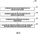
- FIG. 4 a flowchart diagram illustrating an example method 400 to determine the fire spread rate, in accordance with various embodiments of the present disclosure is provided. As depicted in FIG. 4 , steps/operations of determining the fire spread rate are performed by the processing circuitry (such as, but not limited to, the processing circuitry 201 of the controller component 102.
- the processing circuitry such as, but not limited to, the processing circuitry 201 of the controller component 102.
- a processing circuitry determines a first indicating a time in which when the first sensor detects fire particles at a first location. For example, as shown in FIG. 1 , the first location 110 may be angled ⁇ with respect to a line of sight 108 of the first sensor 104.
- a processing circuitry determines a second time indicating a time in which the first sensor detects the fire particles at a second location.
- the second location 111 may be in the line of sight 108 of the first sensor 104.
- a processing circuitry determines a distance between the first location and the second location. For example, as shown in FIG. 1 , the processing circuitry 201 of the controller component 102 may determine a distance Fi between the first location and the second location according to Eq. 1.
- a processing circuitry calculates the fire spread rate according to the first time, the second time, and the distance between the first location and the second location.
- the processing circuitry 201 of the controller component 102 may further determine a fire spread rate according to Eq. 2.
- the fire spread rate measurement component 101 may further include a second sensor 105 located along the wall of the pipeline 103, and in order to determine the fire spread rate, the processing circuitry 201 of the controller component 102 may receive a second signal 121 from the second sensor 105.
- the second sensor 105 may be configured to receive or detect the fire particles radiated from the fire source 107 when the fire particles reach a field of view of the second sensor 105.
- the second signal 121 may include a time stamp when the fire particles reach the field of view of the second sensor 105.
- the second signal 121 may include a third time indicating a time in which the fire particles reach a third location 112.
- a distance between the second location 111 and the third location 112 is L and the third location 112 may be in the line of sight of the second sensor 105.
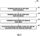
- FIG. 5 a flowchart diagram illustrating an example method 500 to determine the fire spread rate, in accordance with various embodiments of the present disclosure is provided.
- steps of determining the fire spread rate are performed by the processing circuitry (such as, but not limited to, the processing circuitry 201 of the controller component 102.
- a processing circuitry determines a second time indicating a time in which the first sensor detects fire particles at the second location 111.
- the second location 111 may be in the line of sight 108 of the first sensor 104.
- a processing circuitry determines a third time indicating a time in which a second sensor detects the fire particles at a third location 112. For example, as shown in FIG. 1 , the third location 112 may be in the line of sight of the second sensor 105.
- a processing circuitry determines determining a distance between the first sensor and the second sensor. For example, as shown in FIG. 1 , the processing circuitry 201 of the controller component 102 may determine that a distance between the first location and the second location equals L.
- a processing circuitry calculates the fire spread rate according to the second time, the third time, and the distance between the first sensor and the second sensor.
- the processing circuitry 201 of the controller component 102 may further determine a fire spread rate according to Eq. 3.
- the processing circuitry (such as, but not limited to, the processing circuitry 201 of the controller component 102 illustrated in connection with FIG. 2 , discussed above) triggers or activates an extinguisher system 106 according to the fire spread rate.
- the extinguisher system 106 may be located further along the wall of the pipeline 103.
- the processing circuitry 201 of the controller component 102 may generate a third signal 122 according to the fire spread rate and send the third signal to the extinguisher system 106.
- the processing circuitry 201 of the controller component 102 may compare the fire spread rate to a predetermined fire spread rate. In an instance that the fire spread rate is greater than or equal to the predetermined fire spread rate, the processing circuitry 201 of the controller component 102 may determine that the fire event is spreading, and may further generate the third signal 122 according to the fire spread rate and send the third signal to the extinguisher system 106. In an instance that the fire spread rate is smaller than the predetermined fire spread rate, the processing circuitry 201 of the controller component 102 may determine that the fire event is not spreading,
- the extinguisher system 106 may receive the third signal 122 from the controller component 102.
- the third signal 122 may include an activation signal to activate the extinguisher system 106 to extinguish the fire particles.
- the third signal 122 may include the fire spread rate and the fire spread rate may be provided to fire officers through the extinguisher system 106, such that the fire officers may plan the activation of the extinguisher system 106 or plan the evacuation.
- the controller component 102 may determine when to activate the extinguisher system 106 according to a distance between the extinguisher system 106 and the first sensor 104. In some embodiment, a delay period after detecting or receiving the fire particles by the first sensor may be determined according to equation Eq. 4.
Landscapes
- Business, Economics & Management (AREA)
- Emergency Management (AREA)
- Health & Medical Sciences (AREA)
- Public Health (AREA)
- Engineering & Computer Science (AREA)
- Multimedia (AREA)
- Physics & Mathematics (AREA)
- General Physics & Mathematics (AREA)
- Fire Alarms (AREA)
Applications Claiming Priority (1)
| Application Number | Priority Date | Filing Date | Title |
|---|---|---|---|
| IN202311002785 | 2023-01-13 |
Publications (1)
| Publication Number | Publication Date |
|---|---|
| EP4400182A1 true EP4400182A1 (de) | 2024-07-17 |
Family
ID=88690088
Family Applications (1)
| Application Number | Title | Priority Date | Filing Date |
|---|---|---|---|
| EP23207434.4A Pending EP4400182A1 (de) | 2023-01-13 | 2023-11-02 | Vorrichtungen und verfahren zur messung der brandausbreitungsrate |
Country Status (2)
| Country | Link |
|---|---|
| US (1) | US20240238633A1 (de) |
| EP (1) | EP4400182A1 (de) |
Citations (3)
| Publication number | Priority date | Publication date | Assignee | Title |
|---|---|---|---|---|
| US20150021054A1 (en) * | 2013-07-19 | 2015-01-22 | Ian Edward McNamara | Automatic fire targeting and extinguishing system and method |
| US20170319882A1 (en) * | 2014-11-06 | 2017-11-09 | Alan Hart | Wall-mountable spray head unit |
| KR20210018602A (ko) * | 2019-08-06 | 2021-02-18 | (주)아이리녹스 | 실내공간 지능형 화재 초기 진압 시스템 및 그 방법 |
Family Cites Families (5)
| Publication number | Priority date | Publication date | Assignee | Title |
|---|---|---|---|---|
| GB2174003B (en) * | 1985-04-23 | 1988-12-21 | Tekken Constr Co | Automatic fire extinguisher with infrared ray responsive type fire detector |
| US5937077A (en) * | 1996-04-25 | 1999-08-10 | General Monitors, Incorporated | Imaging flame detection system |
| KR100901784B1 (ko) * | 2008-11-11 | 2009-06-11 | 주식회사 창성에이스산업 | 화재 발생 감지시스템 및 그 방법 |
| US10512809B2 (en) * | 2015-03-16 | 2019-12-24 | Fire Rover LLC | Fire monitoring and suppression system |
| CN114935358B (zh) * | 2022-04-12 | 2023-06-16 | 合肥工业大学智能制造技术研究院 | 一种储油场所的自动化火情监测与控制方法 |
-
2023
- 2023-11-02 EP EP23207434.4A patent/EP4400182A1/de active Pending
- 2023-11-28 US US18/521,325 patent/US20240238633A1/en active Pending
Patent Citations (3)
| Publication number | Priority date | Publication date | Assignee | Title |
|---|---|---|---|---|
| US20150021054A1 (en) * | 2013-07-19 | 2015-01-22 | Ian Edward McNamara | Automatic fire targeting and extinguishing system and method |
| US20170319882A1 (en) * | 2014-11-06 | 2017-11-09 | Alan Hart | Wall-mountable spray head unit |
| KR20210018602A (ko) * | 2019-08-06 | 2021-02-18 | (주)아이리녹스 | 실내공간 지능형 화재 초기 진압 시스템 및 그 방법 |
Also Published As
| Publication number | Publication date |
|---|---|
| US20240238633A1 (en) | 2024-07-18 |
Similar Documents
| Publication | Publication Date | Title |
|---|---|---|
| CN114078312B (zh) | 自校准火灾感测设备 | |
| JP7323448B2 (ja) | 緊急事態を検出する緊急検出システム、方法、及びコンピュータソフトウェア | |
| US10037665B2 (en) | Chamber-less smoke sensor | |
| JP6061848B2 (ja) | 火災事象と誤火災事象とを区別するシステム及び方法と同システムを作る方法 | |
| CN112447019A (zh) | 自测试火灾感测设备 | |
| TW200532593A (en) | Fire detection method and fire detector therefor | |
| JP2020038203A5 (de) | ||
| JP2017535754A (ja) | 2波長の散乱光信号に基づくエアロゾルの特徴パラメータの取得方法及びその応用 | |
| EP3832616B1 (de) | Photoelektrischer rauchmelder mit einem einzigen sender und einem einzigen empfänger | |
| KR101864612B1 (ko) | 자동 환기 시스템과 연동되는 화재 경보 방법 및 장치 | |
| US20060103521A1 (en) | Combination airborne substance detector | |
| US10777065B2 (en) | Fire type detection and notification | |
| EP3074737B1 (de) | Flammendetektor für ultraviolettes licht | |
| EP4400182A1 (de) | Vorrichtungen und verfahren zur messung der brandausbreitungsrate | |
| TW202104872A (zh) | 微粒感測器 | |
| CN112284986B (zh) | 用于测量微粒物质的装置和方法 | |
| EP2592609B1 (de) | Kombination aus fotoelektrischem Detektor mit MOS-Gassensor | |
| EP4339913A2 (de) | Verfahren, vorrichtungen und systeme zur infrarotbranderkennung | |
| CN111678614B (zh) | 环境温度探测方法、装置及存储介质 | |
| US7019657B2 (en) | Method, apparatus and system for fire detection | |
| WO2021077158A1 (en) | Improvements related to particle, including sars‑cov‑2, detection and methods therefor | |
| CN112634575B (zh) | 一种检测颗粒浓度自适应烟感探测方法、装置及系统 | |
| US7826976B2 (en) | Method and system for detecting chemical, biological, or radiological agents | |
| TR2024020943A2 (tr) | Oksijensiz Ortam ile Yangın Söndürme Teknolojisi | |
| TWM558282U (zh) | 手機保管箱 |
Legal Events
| Date | Code | Title | Description |
|---|---|---|---|
| PUAI | Public reference made under article 153(3) epc to a published international application that has entered the european phase |
Free format text: ORIGINAL CODE: 0009012 |
|
| STAA | Information on the status of an ep patent application or granted ep patent |
Free format text: STATUS: REQUEST FOR EXAMINATION WAS MADE |
|
| 17P | Request for examination filed |
Effective date: 20231102 |
|
| AK | Designated contracting states |
Kind code of ref document: A1 Designated state(s): AL AT BE BG CH CY CZ DE DK EE ES FI FR GB GR HR HU IE IS IT LI LT LU LV MC ME MK MT NL NO PL PT RO RS SE SI SK SM TR |