EP4400332A9 - Pneu - Google Patents
Pneu Download PDFInfo
- Publication number
- EP4400332A9 EP4400332A9 EP22867044.4A EP22867044A EP4400332A9 EP 4400332 A9 EP4400332 A9 EP 4400332A9 EP 22867044 A EP22867044 A EP 22867044A EP 4400332 A9 EP4400332 A9 EP 4400332A9
- Authority
- EP
- European Patent Office
- Prior art keywords
- belt
- layer
- tire
- strip
- belt reinforcing
- Prior art date
- Legal status (The legal status is an assumption and is not a legal conclusion. Google has not performed a legal analysis and makes no representation as to the accuracy of the status listed.)
- Pending
Links
Images


Classifications
-
- B—PERFORMING OPERATIONS; TRANSPORTING
- B60—VEHICLES IN GENERAL
- B60C—VEHICLE TYRES; TYRE INFLATION; TYRE CHANGING; CONNECTING VALVES TO INFLATABLE ELASTIC BODIES IN GENERAL; DEVICES OR ARRANGEMENTS RELATED TO TYRES
- B60C9/00—Reinforcements or ply arrangement of pneumatic tyres
- B60C9/18—Structure or arrangement of belts or breakers, crown-reinforcing or cushioning layers
- B60C9/20—Structure or arrangement of belts or breakers, crown-reinforcing or cushioning layers built-up from rubberised plies each having all cords arranged substantially parallel
- B60C9/22—Structure or arrangement of belts or breakers, crown-reinforcing or cushioning layers built-up from rubberised plies each having all cords arranged substantially parallel the plies being arranged with all cords disposed along the circumference of the tyre
- B60C9/2204—Structure or arrangement of belts or breakers, crown-reinforcing or cushioning layers built-up from rubberised plies each having all cords arranged substantially parallel the plies being arranged with all cords disposed along the circumference of the tyre obtained by circumferentially narrow strip winding
-
- B—PERFORMING OPERATIONS; TRANSPORTING
- B60—VEHICLES IN GENERAL
- B60C—VEHICLE TYRES; TYRE INFLATION; TYRE CHANGING; CONNECTING VALVES TO INFLATABLE ELASTIC BODIES IN GENERAL; DEVICES OR ARRANGEMENTS RELATED TO TYRES
- B60C9/00—Reinforcements or ply arrangement of pneumatic tyres
- B60C9/18—Structure or arrangement of belts or breakers, crown-reinforcing or cushioning layers
- B60C9/20—Structure or arrangement of belts or breakers, crown-reinforcing or cushioning layers built-up from rubberised plies each having all cords arranged substantially parallel
- B60C9/2003—Structure or arrangement of belts or breakers, crown-reinforcing or cushioning layers built-up from rubberised plies each having all cords arranged substantially parallel characterised by the materials of the belt cords
- B60C9/2009—Structure or arrangement of belts or breakers, crown-reinforcing or cushioning layers built-up from rubberised plies each having all cords arranged substantially parallel characterised by the materials of the belt cords comprising plies of different materials
-
- B—PERFORMING OPERATIONS; TRANSPORTING
- B60—VEHICLES IN GENERAL
- B60C—VEHICLE TYRES; TYRE INFLATION; TYRE CHANGING; CONNECTING VALVES TO INFLATABLE ELASTIC BODIES IN GENERAL; DEVICES OR ARRANGEMENTS RELATED TO TYRES
- B60C9/00—Reinforcements or ply arrangement of pneumatic tyres
- B60C9/18—Structure or arrangement of belts or breakers, crown-reinforcing or cushioning layers
- B60C9/20—Structure or arrangement of belts or breakers, crown-reinforcing or cushioning layers built-up from rubberised plies each having all cords arranged substantially parallel
- B60C2009/2074—Physical properties or dimension of the belt cord
- B60C2009/209—Tensile strength
-
- B—PERFORMING OPERATIONS; TRANSPORTING
- B60—VEHICLES IN GENERAL
- B60C—VEHICLE TYRES; TYRE INFLATION; TYRE CHANGING; CONNECTING VALVES TO INFLATABLE ELASTIC BODIES IN GENERAL; DEVICES OR ARRANGEMENTS RELATED TO TYRES
- B60C9/00—Reinforcements or ply arrangement of pneumatic tyres
- B60C9/18—Structure or arrangement of belts or breakers, crown-reinforcing or cushioning layers
- B60C9/20—Structure or arrangement of belts or breakers, crown-reinforcing or cushioning layers built-up from rubberised plies each having all cords arranged substantially parallel
- B60C9/22—Structure or arrangement of belts or breakers, crown-reinforcing or cushioning layers built-up from rubberised plies each having all cords arranged substantially parallel the plies being arranged with all cords disposed along the circumference of the tyre
- B60C2009/2214—Structure or arrangement of belts or breakers, crown-reinforcing or cushioning layers built-up from rubberised plies each having all cords arranged substantially parallel the plies being arranged with all cords disposed along the circumference of the tyre characterised by the materials of the zero degree ply cords
-
- B—PERFORMING OPERATIONS; TRANSPORTING
- B60—VEHICLES IN GENERAL
- B60C—VEHICLE TYRES; TYRE INFLATION; TYRE CHANGING; CONNECTING VALVES TO INFLATABLE ELASTIC BODIES IN GENERAL; DEVICES OR ARRANGEMENTS RELATED TO TYRES
- B60C9/00—Reinforcements or ply arrangement of pneumatic tyres
- B60C9/18—Structure or arrangement of belts or breakers, crown-reinforcing or cushioning layers
- B60C9/20—Structure or arrangement of belts or breakers, crown-reinforcing or cushioning layers built-up from rubberised plies each having all cords arranged substantially parallel
- B60C9/22—Structure or arrangement of belts or breakers, crown-reinforcing or cushioning layers built-up from rubberised plies each having all cords arranged substantially parallel the plies being arranged with all cords disposed along the circumference of the tyre
- B60C2009/2252—Physical properties or dimension of the zero degree ply cords
- B60C2009/2261—Modulus of the cords
-
- B—PERFORMING OPERATIONS; TRANSPORTING
- B60—VEHICLES IN GENERAL
- B60C—VEHICLE TYRES; TYRE INFLATION; TYRE CHANGING; CONNECTING VALVES TO INFLATABLE ELASTIC BODIES IN GENERAL; DEVICES OR ARRANGEMENTS RELATED TO TYRES
- B60C9/00—Reinforcements or ply arrangement of pneumatic tyres
- B60C9/18—Structure or arrangement of belts or breakers, crown-reinforcing or cushioning layers
- B60C9/20—Structure or arrangement of belts or breakers, crown-reinforcing or cushioning layers built-up from rubberised plies each having all cords arranged substantially parallel
- B60C9/22—Structure or arrangement of belts or breakers, crown-reinforcing or cushioning layers built-up from rubberised plies each having all cords arranged substantially parallel the plies being arranged with all cords disposed along the circumference of the tyre
- B60C2009/2252—Physical properties or dimension of the zero degree ply cords
- B60C2009/2266—Density of the cords in width direction
- B60C2009/2271—Density of the cords in width direction with variable density
-
- B—PERFORMING OPERATIONS; TRANSPORTING
- B60—VEHICLES IN GENERAL
- B60C—VEHICLE TYRES; TYRE INFLATION; TYRE CHANGING; CONNECTING VALVES TO INFLATABLE ELASTIC BODIES IN GENERAL; DEVICES OR ARRANGEMENTS RELATED TO TYRES
- B60C9/00—Reinforcements or ply arrangement of pneumatic tyres
- B60C9/0064—Reinforcements comprising monofilaments
Definitions
- the present invention relates to a pneumatic tire that includes a belt reinforcing layer formed of an organic fiber cord, and the pneumatic tire that allows providing improved durability of the tire and weight reduction and a reduction in rolling resistance of the tire in a compatible manner.
- Patent Literature 1 JP 2002-29214 A
- An object of the present invention is to provide a pneumatic tire that includes a belt reinforcing layer formed of an organic fiber cord, and the pneumatic tire that allows providing improved durability of the tire and weight reduction and a reduction in rolling resistance of the tire in a compatible manner.
- a pneumatic tire according to an embodiment of the present invention for achieving the object includes a tread portion extend in a tire circumferential direction and have an annular shape, a pair of sidewall portions respectively disposed on both sides of the tread portion, a pair of bead portions each disposed on an inner side of the pair of sidewall portions in a tire radial direction, a carcass layer mounted between the pair of bead portions, two layers of belt layers disposed on an outer circumferential side of the carcass layer in the tread portion, and a belt reinforcing layer disposed on an outer circumferential side of the belt layers and comprising at least one belt reinforcing cord spirally wound along a tire circumferential direction.
- a belt cord constituting the belt layers is a monofilament wire having a wire diameter of 0.30 mm or more and 0.45 mm or less.
- the belt reinforcing cord constituting the belt reinforcing layer is an organic fiber cord made of a polyethylene terephthalate fiber.
- the belt reinforcing cord has an intermediate elongation under 2.0 cN/dtex load of from 2.0% to 4.0%.
- the belt reinforcing cords is arranged to form a strip. Circumferential portions of the strip are disposed at intervals in a tire width direction.
- the monofilament wires are used in the belt layer, a thickness of the belt layer can be thinned, and therefore a weight of the tire can be reduced and rolling resistance can be reduced.
- the organic fiber cord formed of the highly rigid polyethylene terephthalate fiber (PET fiber) having an elongation under 2.0 cN/dtex load of from 2.0% to 4.0% is used in the belt reinforcing layer, the durability of the tire can be improved.
- the circumferential portions of the strip in which the belt reinforcing cords are arranged are disposed at intervals in the tire width direction.
- the tire weight can be reduced without excessively increasing the tire mass, and circumferential rigidity of the tire can be increased to reduce strain amplitude of the belt layer, thereby ensuring suppressing belt breakage.
- a ratio of a mutual interval of the strip to a width of the strip constituting the belt reinforcing layer is preferably from 0.05 to 1.50, and the width of the strip is preferably from 5 mm to 15 mm. Setting the ratio of the mutual interval of the strip to the width of the strip constituting the belt reinforcing layer in the range allows sufficiently obtaining an effect of suppressing belt breakage while the weight of the tire is reduced. Further, setting the width of the strip in the range allows improving uniformity of the tire without reducing productivity.
- a strength of the belt cord constituting the belt layer is preferably from 3500 MPa to 4000 MPa. Thus, belt breakage can be suppressed and the durability of the tire can be improved effectively.
- the belt layer is preferably constituted by arranging a plurality of the belt cords.
- belt breakage can be suppressed and the durability of the tire can be improved effectively.
- the belt reinforcing layer preferably includes a full cover layer completely covering the belt layers and a pair of edge cover layers locally covering both end portions of the belt layers.
- a width of the strip constituting the belt reinforcing layer is preferably from 8 mm to 12 mm.
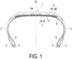
- a pneumatic tire includes a tread portion 1, a pair of sidewall portions 2 respectively disposed on both sides of the tread portion 1, and a pair of bead portions 3 each disposed on an inner side of the pair of sidewall portions 2 in a tire radial direction.
- CL in FIG. 1 denotes a tire equator.
- the tread portion 1, the sidewall portions 2, and the bead portions 3 each extend in a tire circumferential direction and have an annular shape. This forms a toroidal basic structure of the pneumatic tire.
- FIG. 1 is basically based on the illustrated meridian cross-sectional shape, all of the tire components extend in the tire circumferential direction and form the annular shape.
- a plurality of main grooves (four main grooves in the illustrated example) extending in the tire circumferential direction is formed in the outer surface of the tread portion 1; however, the number of main grooves is not limited.
- various grooves and sipes that include lug grooves extending in a tire width direction can also be formed.
- At least one layer (one layer in the illustrated example) of a carcass layer 4 including a plurality of reinforcing cords extending in the tire radial direction is mounted between the pair of left and right bead portions 3.
- a bead core 5 is embedded within each of the bead portions 3, and a bead filler 6 having an approximately triangular cross-sectional shape is disposed on an outer periphery of the bead core 5.
- the carcass layer 4 is folded back around the bead core 5 from an inner side to an outer side in the tire width direction.
- the bead core 5 and the bead filler 6 are wrapped by a body portion (a portion extending from the tread portion 1 through each of the sidewall portions 2 to each of the bead portions 3) and a folded back portion (a portion folded back around the bead core 5 of each bead portion 3 to extend toward each sidewall portion 2 side) of the carcass layer 4.
- the belt layer 7 includes an inner belt layer 7A positioned to the inside in the tire radial direction and an outer belt layer 7B positioned to the outside in the tire radial direction.
- Each of the belt layers 7 includes a plurality of belt cords 7c inclined with respect to the tire circumferential direction, with the belt cords 7c being disposed so as to intersect with one another between the layers.
- an inclination angle of the belt cord 7c with respect to the tire circumferential direction is, for example, set to range from 10° to 40°.
- a belt reinforcing layer 8 is provided on an outer circumferential side of the belt layer 7 for the purpose of improving high-speed durability and reducing road noise.
- the belt reinforcing layer 8 includes a belt reinforcing cord oriented in the tire circumferential direction.
- an angle of the belt reinforcing cord with respect to the tire circumferential direction is set within, for example, from 0° to 5°.
- the belt reinforcing layer 8 necessarily includes a full cover layer 8A that completely covers the belt layers 7, and can discretionarily include a pair of edge cover layers 8B that locally cover both end portions of the belt layers 7 (in the illustrated example, both the full cover layer 8A and the edge cover layers 8B are included).
- the belt reinforcing layer 8 is configured by spirally winding a strip made of at least a single belt reinforcing cord arranged and covered with coating rubber in the tire circumferential direction.
- This strip is configured of the belt reinforcing cord and the coating rubber.
- the belt reinforcing layer 8 desirably has a jointless structure.
- an embodiment of the present invention relates to the belt cord constituting the belt layer 7 and the belt reinforcing cord constituting the belt reinforcing layer 8 described above, the basic overall structure of the tire is not limited to that described above.
- the belt cord 7c constituting the belt layer 7 is not a twisted cord formed by twisting a plurality of wire strands together but is made of a steel monofilament wire.
- a wire diameter of the monofilament wire is 0.30 mm or more, and preferably 0.32 mm or more. Accordingly, the use of the monofilament wire for the belt layer 7 allows suppressing elongation of the belt cord 7c and allows making the belt layer 7 thinner, and thus heat build-up can be suppressed even at extremely high speeds, such as circuit running.
- the wire diameter of the monofilament wire is 0.45 mm or less, and preferably 0.40 mm or less.
- an interval between the monofilament wires is preferably set within, for example, from 0.30 mm to 1.80 mm.
- the specific structure of the monofilament wire is not particularly limited as long as the monofilament wire satisfies the wire diameter described above.
- Various types of monofilament wires that can be used in pneumatic tires can be adopted, including a monofilament wire that is twisted around a wire axis (twisted monofilament), a monofilament wire having a flat cross-sectional shape (flat monofilament), a monofilament wire formed in a helical shape (spiral monofilament), and a monofilament wire formed in a wavy planar shape (2-dimensional wavy monofilament).
- the amount of wire is preferably within a range of from 50 to 280.
- Such a favorable structure of the belt layer 7 is advantageous in improving steering stability while maintaining durability.
- the amount of wire is less than 50, a proportion of the monofilament wires in the belt layer 7 is so small that steering stability may decline.
- the amount of wire exceeds 280, belt-edge-separation possibly occurs.
- a polyester fiber cord having an elongation under 2.0 cN/dtex load of from 2.0% to 4.0%, or preferably from 2.6% to 3.4%, is used as the belt reinforcing cord forming the belt reinforcing layer 8.
- the polyester fiber can include a polyethylene terephthalate fiber (PET fiber).
- the elongation under 2.0 cN/dtex load is an elongation ratio (%) of a sample cord, which is measured under 2.0 cN/dtex load by conducting a tensile test in accordance with JIS-L1017 "Test methods for chemical fiber tire cords" and under the conditions that a length of specimen between grips is 250 mm and a tensile speed is 300 ⁇ 20 mm/minute.
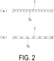
- belt reinforcing cords 8c constituting the belt reinforcing layer 8 are arranged to form a strip S, and circumferential portions of the strip S are disposed at intervals in the tire width direction. That is, when the strip S is wound along the tire circumferential direction, the circumferential portions are separated from one another. In an embodiment of the present invention, thus, the circumferential portions of the strip S constituting the belt reinforcing layer 8 are disposed so as not to be in close contact in the tire width direction.
- the monofilament wires are used in the belt layer 7, a thickness of the belt layer 7 can be thinned, and therefore a weight of the tire can be reduced and rolling resistance can be reduced.
- the organic fiber cord formed of the highly rigid polyethylene terephthalate fiber (PET fiber) having an elongation under 2.0 cN/dtex load of from 2.0% to 4.0% is used in the belt reinforcing layer 8, the durability of the tire can be improved.
- the circumferential portions of the strip S in which the belt reinforcing cords 8c are arranged are disposed at intervals in the tire width direction.
- the tire weight can be reduced without excessively increasing the tire mass, and circumferential rigidity of the tire can be increased to reduce strain amplitude of the belt layer 7, thereby ensuring suppressing belt breakage.
- the belt layer 7 formed of the monofilament wires of the particular wire diameter and the belt reinforcing layer 8 formed of the organic fiber cords having specific physical properties are used in combination to ensure improving steering stability under normal travel conditions and during circuit running. That is, in the belt reinforcing layer 8, the polyethylene terephthalate fiber (PET fiber) having the physical properties described above including high rigidity can be used to improve steering stability under normal travel conditions. Additionally, the belt reinforcing layer 8 effectively suppresses the rising of the belt end portion at high speeds, and thus, can improve high-speed durability.
- PET fiber polyethylene terephthalate fiber
- the use of the monofilament wire described above for the belt layer 7 allows suppressing elongation of the belt cord and making the belt layer 7 thinner, and thus heat build-up can be suppressed even at extremely high speeds, such as circuit running. Accordingly, a reduction in the elastic modulus (rigidity) of the belt reinforcing layer 8 (PET fiber cord) can be prevented, and steering stability at extremely high speeds can be favorably ensured.
- the belt cord that forms the belt layer 7 instead of the monofilament wire, as the belt cord that forms the belt layer 7, elongation can be caused in the belt cord by the twisted structure, and the belt layer 7 cannot be made thinner, and thus, the effects described above cannot be obtained.
- the wire diameter of the monofilament wire is less than 0.30 mm, the monofilament wire is too thin to ensure the sufficient durability of the wire itself, casing belt breakage.
- the wire diameter of the monofilament wire exceeds 0.45 mm, the belt layer 7 cannot be made sufficiently thinner than when using a conventional twisted cord. This increases the tire mass and also tends to deteriorate tire durability.
- a ratio d/w of a mutual interval d (see FIG. 3 ) of the strip to a width w (see FIG. 3 ) of the strip S constituting the belt reinforcing layer 8 is preferably from 0.05 to 1.50. Further, the width w of the strip S is preferably from 5 mm to 15 mm and more preferably from 8 mm to 12 mm. The width w of the strip S is a width including the belt reinforcing cords 8c and the coating rubber.
- the preferable range of the ratio d/w described above is applied to the strip S included in a region in which the circumferential portions of the strip S are disposed at intervals in the tire width direction, and is not applied to the strip S included in a region in which the circumferential portions of the strip S are disposed so as to be in close contact with one another without an interval in the tire width direction.
- the weight of the tire cannot be reduced, and on the other hand, with the ratio d/w of more than 1.50, the circumferential rigidity of the tire cannot be sufficiently ensured and belt breakage cannot be sufficiently suppressed.
- the width w of the strip S of less than 5 mm deteriorates the producibility of the tire, whereas the width w of the strip S in excess of 15 mm deteriorates the uniformity of the tire.
- the belt reinforcing layer 8 preferably includes the full cover layer 8A completely covering the belt layers 7 and the pair of edge cover layers 8B locally covering both end portions of the belt layers 7, and the width w of the strip S constituting the belt reinforcing layer 8 is preferably from 8 mm to 12 mm.
- a strength of the belt cord 7c constituting the belt layer 7 is preferably from 3500 MPa to 4000 MPa.
- dip processing may be optimized, for example.
- an ambient temperature is set within a range of from 210°C to 250°C and a cord tension is set within a range of 2.2 ⁇ 10- 2 N/tex to 6.7 ⁇ 10- 2 N/tex. Accordingly, the desired physical properties as described above can be imparted to the belt reinforcing cord (PET fiber cord).
- cord elastic modulus decreases, and steering stability declines.
- cord tension is greater than 6.7 ⁇ 10- 2 N/tex, cord elastic modulus increases, and thus separation is likely to happen.
- FIG. 3 describes an example in which the circumferential portions of the strip S are disposed at intervals in the tire width direction over the entire region (a center region Ce and shoulder regions Sh) of the tread portion 1 but is not limited to the example.
- the circumferential portions of the strip S can be disposed in close contact with one another without an interval in the tire width direction in the shoulder regions Sh.
- the width of the shoulder region Sh on one side is preferably set to 10 mm to 30 mm.
- the circumferential portions of the strip S are disposed at intervals in the tire width direction, the circumferential portions can be disposed to be positioned on the lower portions of the main grooves formed in the tread portion 1.
- a structure of the belt cord constituting the belt layer, a wire diameter (cord diameter), a strength of the belt cord, the type of the organic fiber used for the organic fiber cord constituting the belt reinforcing layer, an elongation under 2.0 cN/dtex load of the organic fiber cord, presence or absence of an interval of a strip, a ratio of a mutual interval to the width of the strip, and the width w of the strip were set as in Table 1.
- the belt reinforcing layer has a jointless structure in which the strip formed by arranging a plurality of polyethylene terephthalate (PET) fiber cords and covering them with a coating rubber is spirally wound in the tire circumferential direction.
- PET polyethylene terephthalate
- the belt reinforcing layer has a jointless structure in which a strip formed by arranging a plurality of polyethylene naphthalate (PEN) fiber cords and covering them with a coating rubber is spirally wound in the tire circumferential direction.
- PEN polyethylene naphthalate
- Table 1 indicates the case of the PET fiber cord as "PET” and the case of the PEN fiber cord as "PEN” in the columns of the "Type of organic fiber.”
- the cord density in the strip is 50 cords/50 mm.
- the PET fiber cord has a structure of 1100 dtex/2.
- one layer of a full cover layer completely covering the belt layers and two layers of edge cover layers covering only both end portions of the belt layers were provided as the belt reinforcing layer.
- the circumferential portions of the strip of the belt reinforcing layer were disposed so as to be in close contact with one another without an interval in the tire width direction.
- Comparative Examples 2 to 6 and Examples 1 to 7 the circumferential portions of the strip of the belt reinforcing layer were disposed at intervals in the tire width direction.
- test tires were evaluated, according to the following evaluation method, for weight reduction, steering stability during circuit running, and tire durability, and the results are also illustrated in Table 1.
- test tires were assembled on a wheel having a rim size of 15 ⁇ 6J, mounted on a test vehicle (engine displacement 2000 cc), and an air pressure was set to 230 kPa.
- Sensory evaluation was performed by five test drivers on a test course with a paved road for steering stability under a conditions of a speed of from 100 km/h to 270 km/h.
- the respective evaluation results were scored by a 5-point method with Conventional Example 1 being assigned as 3 points (reference), and the average value of the scores of the five test drivers was indicated. Larger values indicate superior steering stability.
- test tires were mounted on a wheel having a rim size of 15 ⁇ 6J and inflated with oxygen to an internal pressure of 230 kPa.
- the tires were held for two weeks in a chamber maintained at a chamber temperature of 60°C, and then oxygen inside the chamber was released, and the chamber was filled with air to an internal pressure of 160 kPa.
- a drum testing machine having a smooth drum surface made of steel and having a diameter of 1707 mm was used to run the pre-treated test tires for 300 km for 10 hours under fluctuating conditions including an ambient temperature of 38 ⁇ 3°C, a running speed of 30 km/hr, a slip angle of 0 ⁇ 5°, and a maximum load of 70 ⁇ 40%, with the load and the slip angle fluctuated by a rectangular wave of 0.083 Hz.
- the tires were cut to open, and the number of portions of belt breakage, the number of belts where belt breakage occurred, and a separation length in a width direction at an end portion in a belt width direction were measured.
- the tires of Examples 1 to 7 were able to improve the tire durability while the weights of the tires were reduced compared with Comparative Example 1 as the reference.
- the tires of Examples 1 to 7 were able to improve steering stability during circuit running compared with Comparative Example 1 as a reference.
- Comparative Example 2 since the elongation under 2.0 cN/dtex load was large and the rigidity of the belt reinforcing layer was too low, belt breakage occurred, the tire durability was reduced, and the steering stability during circuit running was reduced.
- Comparative Example 3 the wire diameter of the belt cord was too thin, and therefore belt breakage occurred and the tire durability was reduced.
- Comparative Example 4 the wire diameter of the belt cord was too thick, and therefore the tire mass was increased. Additionally, separation occurred between layers of an inner belt layer and an outer belt layer and the tire durability was reduced.
- Comparative Example 5 since the elongation under 2.0 cN/dtex load was small and the rigidity of the belt reinforcing layer was too high, separation occurred between the belt layer and the belt reinforcing layer, and the tire durability was reduced.
- Comparative Example 6 the belt reinforcing layer was made of the PEN fiber cords, the elongation of the PEN fiber cords under 2.0 cN/dtex load was small, and the rigidity of the belt reinforcing layer was too high. Therefore, separation occurred between the belt layer and the belt reinforcing layer, and the tire durability was reduced.
Landscapes
- Engineering & Computer Science (AREA)
- Mechanical Engineering (AREA)
- Tires In General (AREA)
Applications Claiming Priority (2)
| Application Number | Priority Date | Filing Date | Title |
|---|---|---|---|
| JP2021145459A JP7773029B2 (ja) | 2021-09-07 | 2021-09-07 | 空気入りタイヤ |
| PCT/JP2022/025933 WO2023037720A1 (fr) | 2021-09-07 | 2022-06-29 | Pneu |
Publications (3)
| Publication Number | Publication Date |
|---|---|
| EP4400332A1 EP4400332A1 (fr) | 2024-07-17 |
| EP4400332A9 true EP4400332A9 (fr) | 2024-10-02 |
| EP4400332A4 EP4400332A4 (fr) | 2025-08-27 |
Family
ID=85506450
Family Applications (1)
| Application Number | Title | Priority Date | Filing Date |
|---|---|---|---|
| EP22867044.4A Pending EP4400332A4 (fr) | 2021-09-07 | 2022-06-29 | Pneu |
Country Status (3)
| Country | Link |
|---|---|
| EP (1) | EP4400332A4 (fr) |
| JP (1) | JP7773029B2 (fr) |
| WO (1) | WO2023037720A1 (fr) |
Family Cites Families (10)
| Publication number | Priority date | Publication date | Assignee | Title |
|---|---|---|---|---|
| JP2002029214A (ja) | 2000-07-13 | 2002-01-29 | Bridgestone Corp | 空気入りラジアルタイヤ |
| JP5217120B2 (ja) * | 2006-06-29 | 2013-06-19 | 横浜ゴム株式会社 | 空気入りタイヤ |
| JP5615665B2 (ja) * | 2010-10-26 | 2014-10-29 | 株式会社ブリヂストン | 空気入りラジアルタイヤ |
| JP5799594B2 (ja) * | 2011-06-07 | 2015-10-28 | 横浜ゴム株式会社 | 乗用車用空気入りラジアルタイヤ |
| JP6003024B2 (ja) * | 2011-08-24 | 2016-10-05 | 横浜ゴム株式会社 | 乗用車用空気入りラジアルタイヤ |
| JP6718334B2 (ja) * | 2016-08-17 | 2020-07-08 | 株式会社ブリヂストン | 空気入りタイヤ |
| JP7151217B2 (ja) * | 2018-07-03 | 2022-10-12 | 横浜ゴム株式会社 | 空気入りラジアルタイヤ |
| JP6737349B2 (ja) * | 2019-01-10 | 2020-08-05 | 横浜ゴム株式会社 | 空気入りラジアルタイヤ |
| JP6809548B2 (ja) * | 2019-02-07 | 2021-01-06 | 横浜ゴム株式会社 | 空気入りラジアルタイヤ |
| JP6680373B1 (ja) * | 2019-02-22 | 2020-04-15 | 横浜ゴム株式会社 | 空気入りタイヤ |
-
2021
- 2021-09-07 JP JP2021145459A patent/JP7773029B2/ja active Active
-
2022
- 2022-06-29 WO PCT/JP2022/025933 patent/WO2023037720A1/fr not_active Ceased
- 2022-06-29 EP EP22867044.4A patent/EP4400332A4/fr active Pending
Also Published As
| Publication number | Publication date |
|---|---|
| EP4400332A1 (fr) | 2024-07-17 |
| JP7773029B2 (ja) | 2025-11-19 |
| JP2023038639A (ja) | 2023-03-17 |
| EP4400332A4 (fr) | 2025-08-27 |
| WO2023037720A1 (fr) | 2023-03-16 |
Similar Documents
| Publication | Publication Date | Title |
|---|---|---|
| US20220161602A1 (en) | Pneumatic radial tire | |
| US20220041017A1 (en) | Pneumatic tire | |
| EP2689939A1 (fr) | Câblé d'acier pour renforcer un article en caoutchouc et pneumatique radial l'utilisant | |
| US20130206302A1 (en) | Pneumatic tire | |
| EP3552841B1 (fr) | Pneumatique | |
| US6926053B2 (en) | Pneumatic tire variable elasticity modules metallic band cord | |
| US20220134803A1 (en) | Pneumatic tire | |
| US20220126629A1 (en) | Pneumatic radial tire | |
| US7438104B2 (en) | Radial tire | |
| JP5424474B2 (ja) | ランフラットタイヤ | |
| EP4257371B1 (fr) | Pneumatique | |
| EP4134247B1 (fr) | Pneumatique | |
| US20220048328A1 (en) | Pneumatic radial tire | |
| US20220274445A1 (en) | Pneumatic tire | |
| EP4400332A9 (fr) | Pneu | |
| US12539717B2 (en) | Pneumatic tire | |
| EP4393722A1 (fr) | Pneumatique | |
| US20220266633A1 (en) | Pneumatic tire | |
| JP7088402B2 (ja) | 空気入りラジアルタイヤ | |
| US11780267B2 (en) | Pneumatic tire | |
| EP4706988A1 (fr) | Pneumatique | |
| EP4596258A1 (fr) | Pneumatique | |
| EP4570519A1 (fr) | Pneumatique | |
| JP7572605B2 (ja) | 空気入りタイヤ |
Legal Events
| Date | Code | Title | Description |
|---|---|---|---|
| STAA | Information on the status of an ep patent application or granted ep patent |
Free format text: STATUS: THE INTERNATIONAL PUBLICATION HAS BEEN MADE |
|
| PUAI | Public reference made under article 153(3) epc to a published international application that has entered the european phase |
Free format text: ORIGINAL CODE: 0009012 |
|
| STAA | Information on the status of an ep patent application or granted ep patent |
Free format text: STATUS: REQUEST FOR EXAMINATION WAS MADE |
|
| 17P | Request for examination filed |
Effective date: 20240226 |
|
| AK | Designated contracting states |
Kind code of ref document: A1 Designated state(s): AL AT BE BG CH CY CZ DE DK EE ES FI FR GB GR HR HU IE IS IT LI LT LU LV MC MK MT NL NO PL PT RO RS SE SI SK SM TR |
|
| DAV | Request for validation of the european patent (deleted) | ||
| DAX | Request for extension of the european patent (deleted) | ||
| A4 | Supplementary search report drawn up and despatched |
Effective date: 20250725 |
|
| RIC1 | Information provided on ipc code assigned before grant |
Ipc: B60C 9/22 20060101AFI20250721BHEP Ipc: B60C 9/00 20060101ALI20250721BHEP Ipc: B60C 9/20 20060101ALI20250721BHEP |
|
| GRAP | Despatch of communication of intention to grant a patent |
Free format text: ORIGINAL CODE: EPIDOSNIGR1 |
|
| STAA | Information on the status of an ep patent application or granted ep patent |
Free format text: STATUS: GRANT OF PATENT IS INTENDED |
|
| INTG | Intention to grant announced |
Effective date: 20260302 |