EP4400434B1 - Système d'introduction de tube de remplissage, procédé de fixation d'un tube de remplissage et utilisation d'un dispositif d'insertion - Google Patents
Système d'introduction de tube de remplissage, procédé de fixation d'un tube de remplissage et utilisation d'un dispositif d'insertion Download PDFInfo
- Publication number
- EP4400434B1 EP4400434B1 EP23151531.3A EP23151531A EP4400434B1 EP 4400434 B1 EP4400434 B1 EP 4400434B1 EP 23151531 A EP23151531 A EP 23151531A EP 4400434 B1 EP4400434 B1 EP 4400434B1
- Authority
- EP
- European Patent Office
- Prior art keywords
- filling tube
- section
- insertion device
- tube
- holding
- Prior art date
- Legal status (The legal status is an assumption and is not a legal conclusion. Google has not performed a legal analysis and makes no representation as to the accuracy of the status listed.)
- Active
Links
Images


Classifications
-
- B—PERFORMING OPERATIONS; TRANSPORTING
- B65—CONVEYING; PACKING; STORING; HANDLING THIN OR FILAMENTARY MATERIAL
- B65B—MACHINES, APPARATUS OR DEVICES FOR, OR METHODS OF, PACKAGING ARTICLES OR MATERIALS; UNPACKING
- B65B9/00—Enclosing successive articles, or quantities of material, e.g. liquids or semiliquids, in flat, folded, or tubular webs of flexible sheet material; Subdividing filled flexible tubes to form packages
- B65B9/10—Enclosing successive articles, or quantities of material, in preformed tubular webs, or in webs formed into tubes around filling nozzles, e.g. extruded tubular webs
- B65B9/20—Enclosing successive articles, or quantities of material, in preformed tubular webs, or in webs formed into tubes around filling nozzles, e.g. extruded tubular webs the webs being formed into tubes in situ around the filling nozzles
- B65B9/22—Forming shoulders; Tube formers
-
- B—PERFORMING OPERATIONS; TRANSPORTING
- B65—CONVEYING; PACKING; STORING; HANDLING THIN OR FILAMENTARY MATERIAL
- B65B—MACHINES, APPARATUS OR DEVICES FOR, OR METHODS OF, PACKAGING ARTICLES OR MATERIALS; UNPACKING
- B65B9/00—Enclosing successive articles, or quantities of material, e.g. liquids or semiliquids, in flat, folded, or tubular webs of flexible sheet material; Subdividing filled flexible tubes to form packages
- B65B9/10—Enclosing successive articles, or quantities of material, in preformed tubular webs, or in webs formed into tubes around filling nozzles, e.g. extruded tubular webs
- B65B9/20—Enclosing successive articles, or quantities of material, in preformed tubular webs, or in webs formed into tubes around filling nozzles, e.g. extruded tubular webs the webs being formed into tubes in situ around the filling nozzles
- B65B9/2035—Tube guiding means
-
- B—PERFORMING OPERATIONS; TRANSPORTING
- B65—CONVEYING; PACKING; STORING; HANDLING THIN OR FILAMENTARY MATERIAL
- B65B—MACHINES, APPARATUS OR DEVICES FOR, OR METHODS OF, PACKAGING ARTICLES OR MATERIALS; UNPACKING
- B65B5/00—Packaging individual articles in containers or receptacles, e.g. bags, sacks, boxes, cartons, cans, jars
- B65B5/10—Filling containers or receptacles progressively or in stages by introducing successive articles, or layers of articles
- B65B5/101—Filling containers or receptacles progressively or in stages by introducing successive articles, or layers of articles by gravity
- B65B5/103—Filling containers or receptacles progressively or in stages by introducing successive articles, or layers of articles by gravity for packaging pills or tablets
Definitions
- the present invention relates to a filling tube insertion device system, a method for fastening a filling tube in a packaging device for small piece goods and the use of an insertion device for fastening a filling tube in a packaging device.
- a system for filling small-sized products into blister bags through a filling tube with spreading means extending outwards in the longitudinal direction of the filling tube is known, for example, from EP 3 912 918 A1 known.
- Packaging equipment is used, among other things, in blister machines, such as those used in WO 2013/034504 A1 Depending on the level of expansion, the blister machines comprise several hundred storage and dispensing stations, each of which contains several
- portions or dietary supplement portions (hereinafter referred to as portions, more generally also as small-unit goods) of a specific type are stored. Upon request, individual portions can be dispensed from the storage and dispensing stations and are then fed via a guide device to a packaging device, where the portions are packaged or blistered.
- a packaging material web is formed by the packaging device into a blister tube containing a plurality of blister bags arranged one behind the other.
- a flexible, elongated packaging material web is fed to the packaging device via a packaging material guide.
- the packaging material web is usually formed into a tube-like shape by a forming means and joined, among other things, in the running direction.
- the packaging material tube is then welded transversely to the running direction to form a partially closed blister bag, into which one or more portions are then transferred.
- the packaging equipment has state-of-the-art usually has a filling tube which extends into the packaging material tube via a receiving opening of the packaging material guide and transfers the portions to be blistered to a partially closed blister bag.
- a prior art filling tube comprises a plurality of spreading means that keep the packaging material tube tubular or spread it open.
- the spreading means are elastically deformable at least in sections and, in an untensioned state, extend outwards from the dispensing section in the longitudinal direction of the filling tube. This ensures that the spreading means keep this packaging material tube open or spread it open to receive the portions.
- a further task of the spreading means is to shape the packaging material tube in such a way that it can be welded without wrinkles.
- the filling tube insertion device system comprises an insertion device which has a cylindrical central part with an actuating end section and an opposite holding end section, wherein a holding means is arranged on the holding section, and a filling tube which has fastening means and a hollow cylindrical tube section with a receiving section for small piece goods and an opposite dispensing section, wherein at least two elastically deformable spreading means, each with a spreading means end, are arranged on the dispensing section, wherein the spreading means, in an untensioned state, extend outwards from the dispensing section in the longitudinal direction of the filling tube.
- the cylindrical central part and the holding means of the insertion device are designed such that they can be guided through the hollow cylindrical tube section and that the holding means and the spreading means ends are coordinated with one another such that the spreading means ends can be releasably clamped to the holding means. Furthermore, it is provided that the cylindrical central part of the guide device is adapted to the filling tube in such a way that the actuating section projects into the receiving section when the spreading means ends are clamped.
- the inventive coordination of the two components of the filling tube insertion device system ensures that the system can be easily attached to the packaging device in the "tensioned state" when the guide means is guided through the filling tube and the spreading means are clamped to the holding means. Since the invention provides that the actuating section in the clamped state of the Once the ends of the spreader protrude into the receiving section accessible to the user, the insertion device can be easily removed. To do this, the detachable attachment of the spreader to the holding device must be released, then the insertion device can be easily removed (normally upwards).
- the two expansion devices are clamped to the holding device during insertion of the filling tube, it is ensured that they do not place excessive strain on the tubular packaging material. Damage to other components of the packaging device and the risk of injury to the user are also avoided by clamping the ends of the expansion devices. Furthermore, the filling tube can be inserted much more quickly with the system according to the invention, since less care is required to avoid the aforementioned risks.
- a further advantage is that the filling tube can be transported, shipped and stored more safely in the "clamped" state, whereby a safety device can be provided to prevent accidental release of the clamping.
- the holding means of the insertion device is adapted to the filling tube in such a way that the holding means can be guided through it.
- the insertion device After the filling tube has been inserted using the filling tube insertion device system according to the invention, the insertion device must be removed. This requires that the expansion means ends be released from the holding means. With a simple design of the insertion device, this can be achieved, for example, simply by moving the holding means a little further in the insertion direction via the actuating section; the expansion means ends then "jump" out of the holding means, and the insertion device can usually be removed in the opposite direction to the insertion direction. Alternatively, the holding means can be rotated via the actuating section to release the clamping. In both variants, improper use can cause damage to the packaging material web and/or other components.
- a preferred embodiment provides for the cylindrical central part to have a hollow outer tube and an inner rod movably mounted in the hollow outer tube with opposite end sections, with the holding means arranged at one end section.
- the section of the inner rod opposite the end section with the holding means can, for example, be moved slightly downwards by a user (where the length of the protruding section defines the distance of movement), and the releasable tension of the spreading means is released.
- the outer tube has at least one stop
- the hollow cylindrical tube section, the receiving or dispensing section has an inner stop, which are coordinated such that the stop prevents the stop from being moved past.
- This design prevents a relative movement of the insertion device as such to the filling tube at a certain position. However, the movement of the inner tube via the actuating section is not prevented.
- the retaining means is preferably cup-shaped.
- the inner rod can also be slightly twisted; this requires a corresponding design of the retaining means.
- the object is further achieved by a method for fastening a filling tube in a packaging device for small piece goods, wherein firstly an insertion device which has a cylindrical central part with an actuating end section and an opposite holding end section, wherein a holding means is arranged on the holding section, and a filling tube are provided, wherein the filling tube has fastening means, a hollow cylindrical tube section with a receiving section for small piece goods and an opposite dispensing section, wherein at least two elastically deformable spreading means, each with a spreading means end, are arranged on the dispensing section and wherein the spreading means extend outwards from the dispensing section in the longitudinal direction of the filling tube in an untensioned state.
- the insertion device is then guided through the filling tube in such a way that the holding end section is arranged in the region of the spreading means ends and the actuating end section is arranged at the receiving section and the spreading means ends are releasably clamped to the holding means, whereby a filling tube-introduction device combination is formed, wherein the holding means is adapted to the filling tube in such a way that the holding means can be guided through the filling tube with the spreading means ends clamped in.
- the filling tube-insertion device combination is then guided over the holding end section with the clamped spreading means ends in sections in an insertion direction through a receiving opening of a packaging material guide of the packaging device, the filling tube is fastened to a filling tube adjusting means of the packaging device, the spreading means ends are released from the holding means of the insertion device, whereby the spreading means move into an unclamped state, and the insertion device is removed from the filling tube
- the (possibly new or cleaned) filling tube is attached in or to the packaging device and the insertion device is free for further use.
- the spreading means ends are released from the holding means of the insertion device by moving the insertion device further in the insertion direction after the filling tube has been fastened to the filling tube adjusting means.
- the outer tube has at least one stop means and the hollow cylindrical tube section has an inner stop, whereby the movement of the insertion device in the insertion direction can be limited by the inner stop and the stop means.
- an insertion device for fastening a filling tube in a packaging device, wherein the insertion device has a cylindrical central part with an actuating end section and an opposite holding end section, wherein a holding means is arranged on the holding section, wherein the cylindrical central part and the holding means of the insertion device are designed such that they can be guided through a hollow cylindrical tube section of the filling tube, wherein the holding means is designed such that spreading means ends of elastically deformable spreading means, which are arranged at a discharge section of the filling tube, can be releasably clamped on the holding means, and wherein the cylindrical central part of the guide device is adapted to the filling tube in such a way that the actuating section can be actuated after the filling tube has been fastened.
- the cylindrical central part has at least one guide means which can be guided through the hollow cylindrical pipe section.
- the cylindrical central part comprises a hollow outer tube and an inner rod movably mounted in the hollow outer tube with opposite end sections, wherein the holding means is arranged at one end section.
- the hollow outer tube has at least one stop means and/or the holding means is cup-shaped.
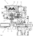
- Figure 1 shows a packaging device for blister machines as is known from the prior art. Such a packaging device is disclosed, for example, in EP 3 385 174 A1 .
- the packaging device comprises a receiving section 320 of a Figure 1 a filling tube (not shown in detail) which is fastened in the packaging device.
- a packaging material guide 20 can be seen, which in the packaging device shown here is designed in the manner of a forming shoulder.
- the packaging material web is fed to this packaging material guide, which forms the packaging material web downwards into a tubular shape, with a hollow cylindrical tube section of the filling tube (not shown) extending into this tubularly formed packaging material web.
- a filling tube adjustment means 50 is arranged, to which the filling tube itself is detachably fastened in or on the packaging device.
- a first joining device 30 is arranged, which vertically joins the tubular packaging material web in an overlapping area.
- a second joining device 40 is arranged, by means of which the packaging material tube closed by the first joining device is joined transversely to the running direction.
- a filled tube section or partially closed blister bag is formed into a closed blister bag, and a new, bottom-closed blister bag to be filled is provided above the second joining device.
- two joining means 41, 42 of the second joining device are moved together. Once the joint is created, the joining means are moved apart.
- the second joining device is movable in the direction of travel of the packaging material web, as disclosed in more detail in the aforementioned publication.
- FIG. 2 shows a preferred embodiment of the filling tube insertion device system 100 according to the invention.
- This comprises a filling tube 300 with a hollow cylindrical tube section 310 with a receiving section 320 for small items, for example in the form of pharmaceutical portions or food supplement portions, which in the embodiment shown is designed like a type of funnel, as well as a dispensing section 330 opposite the receiving section at the lower end of the hollow cylindrical tube section.
- two elastically deformable spreading means 340 are arranged in the dispensing section 330.
- the filling tube insertion device system 100 further comprises an insertion device 200 with a cylindrical central part 210 with an actuating end section 220 and an opposite holding end section 230.
- a holding means 240 is arranged at the holding end section 230, which in the embodiment shown is pot-shaped.
- a guide means 250 is arranged in the upper section of the cylindrical central part 210, and a stop means 215 is arranged in the lower section, wherein the stop means in the embodiment shown is of the same shape as the guide means. and can cooperate with the inner stop 311 so as to limit movement of the insertion device in the filling tube.
- the cylindrical central part 210 and the holding means 240 of the insertion device are designed such that they can be guided through the filling tube or the hollow cylindrical tube section 310 of the filling tube. It is further provided that the holding means 240 and the expanding means ends 341 are coordinated with one another such that the expanding means ends can be releasably clamped to the holding means 240. Finally, it is provided that the cylindrical central part 210 of the guide device 200 is adapted to the filling tube 300 or the hollow cylindrical tube section 310 such that the actuating section protrudes into the receiving section when the expanding means ends are clamped.
- FIGs 3a and 3b Two further views of the preferred embodiment of the filling tube insertion device system 100 are shown, in both views the insertion device is inserted into the filling tube.
- the expansion means ends 341 are clamped in the pot-shaped holding means 240, so that the expansion means ends no longer extend outward from the hollow cylindrical tube section.
- the insertion device is also connected to the filling tube to a certain extent. Although the connection is detachable, it is nevertheless such that the insertion device cannot be separated without the application of force.
- Figure 3b the spreading means ends are not clamped in the holding means 240, and in contrast to Figure 3a It can be seen that the ends of the expansion means extend outward from the filling tube. In this unclamped state, the insertion device can be removed from the filling tube, which in practice is done by pulling the insertion device out upwards.
- Figures 4a - 4c show detailed views of the filling tube insertion system used in the packaging device in the tensioned state, which is shown in figure 3a is shown.
- Figure 4b It is clearly visible that the spreading means ends 341 are moved "inward” by being arranged or clamped in the holding means 240, i.e., they no longer protrude beyond the inner diameter of the hollow cylindrical tube section, so that insertion of the filling tube insertion device system in the clamped state from above is possible without damaging the (not shown) packaging material web.
- the packaging material web which is formed in a tubular shape around the hollow cylindrical tube section at the height of the latter, would be joined together in the region of the hollow cylindrical tube section.
- the tubular section of the packaging material web has an inner diameter that is only slightly larger than the outer diameter of the hollow cylindrical tube section 311 and the discharge section, so that it is evident that inserting the filling tube in the clamped state avoids damage to the packaging material web.
- FIGS. 5a - 5c show detailed views of the inserted, unclamped filling tube.
- the spreading means ends 341 extend over the outer circumference of the hollow cylindrical tube section 310, against whose outer circumference the packaging material tube rests; it is clear that damage can occur if the spreading means tips are not clamped.
- Figure 5c It is clearly visible that the joining means of the second joining device are located directly downstream of the unclamped spreading means ends, i.e., the "bottom" of the partially closed blister pack to be filled is positioned directly below the spreading means ends.
- the spreading means ends When the spreading means ends are released when a packaging material web is present (which should normally be the case), they spread the packaging material web just above the "bottom" so that the portions can be arranged in a space-saving manner. At the same time, the packaging material web (which at this point is already joined together to form a tube) limits the outward movement of the spreading means ends.
- Figures 6a - 6d show views of a preferred embodiment of the insertion device as used in the filling tube insertion device system, wherein Figures 6b and 6d
- the insertion device 200 comprises a central cylindrical middle part 210, which in the embodiment shown comprises a hollow outer tube 211 in which an inner rod 212 is movably mounted.
- the inner rod 212 exits via the ends of the hollow outer tube.
- the holding means 240 is attached to the lower end section of the inner rod 212, which in this embodiment defines the holding end section 230.
- Figures 6b and 6d It is clearly visible that the holding means forms a receiving pot, which is designed to clamp the correspondingly designed expansion means ends.
- the expansion means ends press against the inner wall 241 of the receiving pot, creating a frictional connection that holds the insertion device in or on the filling tube (until a greater force is applied to release it).
- the receiving pot comprises recesses, so that the expansion means can be released or released by twisting the holding means.
- a guide means 250 is arranged, which is adapted to the inner diameter of the hollow cylindrical tube section and ensures a clean, coaxial movement during the insertion and removal of the insertion device.
- a stop means 215 is arranged, which in this embodiment corresponds in shape to the guide means and also performs its function. In addition, it interacts with the inner stop 311 (see Figures 3a - 4c ) together, and limits the relative movement of the outer tube 211 to the hollow cylindrical tube section 310.
- the inner stop is arranged such that when the stop means is applied to the inner stop, the spreading means ends can be clamped in the holding means.
- a handle 260 is arranged, which facilitates the handling of the insertion device during Releasing the clamping of the expansion means ends is simplified.
- the inner rod 212 protrudes from the hollow outer tube and includes a push button 280 at its upper end section 213.
- a spring means 270 is arranged between the push button 280 and the upper end of the outer tube 211, which preloads the inner tube upward via the attachment to the push button.
- the spring force can be overcome, and the inner tube moves relative to the hollow outer tube; in the illustrated orientation, "downward.” If the expansion means ends are clamped during this relative movement, the clamping is released by the movement, and the expansion means (ends) move into the unclamped state.
- Figures 7a - 7h illustrate various stages of an embodiment of the method according to the invention for fastening a filling tube in a packaging device.
- Figures 7a - 7h Only the filling tube insertion device system 100 and relevant parts of the packaging device are shown. For clarity, only the components relevant to the process are provided with reference numerals; a detailed description of the filling tube and the insertion device was provided with reference to previous figures.
- the insertion device 200 and the filling tube 300 are provided ( Figure 7a ).
- the insertion device is then guided through the filling tube in such a way that the holding end section 230 is arranged in the region of the spreading means ends 341 and the actuating end section 220 is arranged at the receiving section 320, and the spreading means ends 341 are releasably clamped to the holding means 240 ( Figure 7b ), thereby forming a filling tube-introducer combination 400.
- the filling tube-insertion device combination 400 is guided via the holding end section with the clamped spreading means ends in sections in an insertion direction through the receiving opening 21 of the packaging material guide 20 ( Figures 7c, 7d ).
- the filling tube 300 is then attached to the filling tube adjustment means 50 of the packaging device, whereby the alignment of the filling tube-introducer combination is determined in the packaging facility ( Figure 7e ).
- the spreading means ends 341 are released from the holding means 240 of the insertion device, whereby the spreading means move into an unstressed state (transition Figure 7e -> 7f ).
- this release takes place by pressing the push button downwards so that the spreading means ends are released from the holding means 240 and move into the untensioned state ( Figure 7f ).
- the movement into the unstressed state is limited by the packaging material web (not shown), which is aligned by the spreading means to receive the drug portions (i.e., opened or held open).
- the insertion device is moved out of the filling tube ( Figures 7g, 7h ).
Landscapes
- Engineering & Computer Science (AREA)
- Mechanical Engineering (AREA)
- Containers And Plastic Fillers For Packaging (AREA)
Claims (13)
- Système de dispositif d'insertion de tube de remplissage (100), comprenantun dispositif d'insertion (200) qui présente une partie centrale cylindrique (210) avec une section d'extrémité d'actionnement (220) et une section d'extrémité de maintien (230) opposée, un moyen de maintien (240) étant disposé sur la section d'extrémité de maintien (230),un tube de remplissage (300) qui présente des moyens de fixation (350), une section de tube cylindrique creuse (310) avec une section de réception (320) pour les petites marchandises et une section de distribution (330) opposée, au moins deux moyens d'écartement (340) déformables élastiquement, chacun avec une extrémité de moyen d'écartement (341), étant disposés sur la section de distribution (330), les moyens d'écartement (340) s'étendant à l'état non tendu de la section de distribution (330) vers l'extérieur dans le sens longitudinal du tube de remplissage (300),la partie centrale cylindrique (210) ainsi que le moyen de maintien (240) du dispositif d'insertion (200) étant conçus de telle sorte qu'ils puissent être guidés à travers la section de tube cylindrique creuse (310),le moyen de maintien (240) et les extrémités de moyen d'écartement (341) étant adaptés l'un à l'autre de telle sorte que les extrémités de moyen d'écartement puissent être serrées de manière amovible sur le moyen de maintien,et la partie centrale cylindrique (210) du dispositif de guidage (200) étant adaptée au tube de remplissage (300) de telle sorte que la section d'extrémité d'actionnement (220) pénètre dans la section de réception (320) lorsque les extrémités du moyen d'écartement sont serrées.
- Système de dispositif d'insertion de tube de remplissage (100) selon la revendication 1,
caractérisé en ce que la partie centrale cylindrique (210) présente au moins un moyen de guidage (250) qui peut être guidé à travers la section de tube cylindrique creuse (310). - Système de dispositif d'insertion de tube de remplissage (100) selon la revendication 1 ou 2,
caractérisé en ce que la partie centrale cylindrique (210) présente un tube extérieur creux (211) ainsi qu'une tige intérieure (212) logée de manière mobile dans le tube extérieur creux (211) et comportant des sections d'extrémité opposées (213, 214), les moyens de maintien (240) étant disposés sur une section d'extrémité. - Système de dispositif d'insertion de tube de remplissage (100) selon la revendication 3,
caractérisé en ce que le tube extérieur creux (211) présente au moins un moyen d'arrêt (215) et la section de tube cylindrique creuse (310), la section de réception (320) ou la section de distribution (330) présentent une butée intérieure (311), qui sont adaptées de telle sorte que la butée empêche le moyen d'arrêt de passer. - Système de dispositif d'insertion de tube de remplissage (100) selon l'une des revendications 1 à 4,
caractérisé en ce que le moyen de maintien (240) est en forme de pot. - Procédé de fixation d'un tube de remplissage (300) dans un dispositif d'emballage (10) pour petites marchandises, dans lequelun dispositif d'insertion (200) est prévu, lequel présente une partie centrale cylindrique (210) avec une section d'extrémité d'actionnement (220) et une section d'extrémité de maintien (230) opposée, un moyen de maintien (240) étant disposé sur la section d'extrémité de maintien (230),un tube de remplissage (300) est prévu, lequel présente des moyens de fixation (350), une section de tube cylindrique creuse (310) avec une section de réception (320) pour les petites marchandises et une section de distribution (330) opposée, au moins deux moyens d'écartement (340) déformables élastiquement, chacun avec une extrémité (341), étant disposés sur la section de distribution (330), les moyens d'écartement (340) s'étendant, à l'état non tendu, vers l'extérieur à partir de la section de distribution (330) dans le sens longitudinal du tube de remplissage (300),le dispositif d'insertion (200) est guidé à travers le tube de remplissage (300) de telle sorte que la section d'extrémité de maintien (230) soit disposée dans la zone des extrémités des moyens d'écartement (341) et que la section d'extrémité d'actionnement (220) soit disposée au niveau de la section de réception (320),les extrémités des moyens d'écartement (341) sont serrées de manière amovible sur le moyen de maintien (240), ce qui forme une combinaison tube de remplissage-dispositif d'insertion (400), le moyen de maintien (240) étant adapté au tube de remplissage de telle sorte que le moyen de maintien (240) avec les extrémités des moyens d'écartement serrées peut être guidé à travers le tube de remplissage,la combinaison tube de remplissage-dispositif d'insertion (400) est guidée par sections dans une direction d'insertion à travers une ouverture de réception (21) d'un guide de matériau d'emballage (20) du dispositif d'emballage (10) via la section d'extrémité de maintien avec les extrémités de moyen d'écartement serrées (341),le tube de remplissage (300) est fixé à un moyen d'ajustement de tube de remplissage (30) du dispositif d'emballage (10),les extrémités de moyen d'écartement (341) sont détachées du moyen de maintien (240) du dispositif d'insertion, ce qui fait passer le moyen d'écartement dans un état non tendu, etle dispositif d'insertion (200) est retiré du tube de remplissage (300).
- Procédé de fixation d'un tube de remplissage (300) dans un dispositif d'emballage (10) pour petites marchandises selon la revendication 6,
caractérisé en ce que les extrémités de moyen d'écartement (341) sont détachées du moyen de maintien (240) du dispositif d'insertion en continuant à déplacer le dispositif d'insertion (200) dans le sens d'insertion après avoir fixé le tube de remplissage (300) au moyen d'ajustement de tube de remplissage (30). - Procédé de fixation d'un tube de remplissage (300) dans un dispositif d'emballage (10) pour petites marchandises selon la revendication 7,le tube extérieur (211) présentant au moins un moyen d'arrêt (215) et la section de tube cylindrique creuse (310) présentant une butée intérieure (311),caractérisé en ce que le mouvement du dispositif d'insertion dans le sens d'insertion est limité par la butée intérieure et le moyen d'arrêt.
- Utilisation d'un dispositif d'insertion (200) pour fixer un tube de remplissage (300) dans un dispositif d'emballage (10),le dispositif d'insertion (200) présentant une partie centrale cylindrique (210) avec une section d'extrémité d'actionnement (220) et une section d'extrémité de maintien (230) opposée, un moyen de maintien (240) étant disposé sur la section d'extrémité de maintien (230),la partie centrale cylindrique (210) ainsi que le moyen de maintien (240) du dispositif d'insertion (200) étant conçus de telle sorte qu'ils peuvent être guidés à travers une section de tube cylindrique creuse (310) du tube de remplissage,le moyen de maintien (240) étant conçu de telle sorte que les extrémités (341) des moyens d'écartement (340) déformables élastiquement, qui sont disposées au niveau d'une section de distribution (330) du tube de remplissage (330), peuvent être serrées de manière amovible sur le moyen de maintien,et la partie centrale cylindrique (210) du dispositif de guidage (200) étant adaptée au tube de remplissage (300) de telle sorte que la section d'extrémité d'actionnement (220) puisse être actionnée après la fixation du tube de remplissage.
- Utilisation d'un dispositif d'insertion (200) pour fixer un tube de remplissage (300) dans un dispositif d'emballage (10) selon la revendication 9,
caractérisé en ce que la partie centrale cylindrique (210) présente au moins un moyen de guidage (250) qui peut être guidé à travers la section de tube cylindrique creuse (310). - Utilisation d'un dispositif d'insertion (200) pour fixer un tube de remplissage (300) dans un dispositif d'emballage (10) selon la revendication 9 ou 10,
caractérisé en ce que la partie centrale cylindrique (210) présente un tube extérieur creux (211) ainsi qu'une tige intérieure (212) mobile dans le tube extérieur creux (211) et comportant des sections d'extrémité opposées (213, 214), le moyen de maintien (240) étant disposé à l'une des extrémités. - Utilisation d'un dispositif d'insertion (200) pour fixer un tube de remplissage (300) dans un dispositif d'emballage (10) selon la revendication 11,
caractérisée en ce que le tube extérieur creux (211) présente au moins un moyen d'arrêt (215). - Utilisation d'un dispositif d'insertion selon l'une des revendications 9 à 12,
caractérisée en ce que le moyen de maintien (240) est en forme de pot.
Priority Applications (5)
| Application Number | Priority Date | Filing Date | Title |
|---|---|---|---|
| EP23151531.3A EP4400434B1 (fr) | 2023-01-13 | 2023-01-13 | Système d'introduction de tube de remplissage, procédé de fixation d'un tube de remplissage et utilisation d'un dispositif d'insertion |
| PCT/EP2023/081426 WO2024149492A1 (fr) | 2023-01-13 | 2023-11-10 | Système de dispositif d'insertion de tube de remplissage, procédé de fixation d'un tube de remplissage, et utilisation d'un dispositif d'insertion |
| JP2025540831A JP2026500971A (ja) | 2023-01-13 | 2023-11-10 | 充填チューブ挿入装置システム、充填チューブを固定する方法、及び、挿入装置の使用 |
| CN202380091286.6A CN120513205A (zh) | 2023-01-13 | 2023-11-10 | 进料管-导入装置系统、用于紧固进料管的方法以及导入装置的用途 |
| KR1020257019241A KR20250134073A (ko) | 2023-01-13 | 2023-11-10 | 충전 튜브 삽입 장치 시스템, 충전 튜브 고정 방법 및 삽입 장치의 용도 |
Applications Claiming Priority (1)
| Application Number | Priority Date | Filing Date | Title |
|---|---|---|---|
| EP23151531.3A EP4400434B1 (fr) | 2023-01-13 | 2023-01-13 | Système d'introduction de tube de remplissage, procédé de fixation d'un tube de remplissage et utilisation d'un dispositif d'insertion |
Publications (3)
| Publication Number | Publication Date |
|---|---|
| EP4400434A1 EP4400434A1 (fr) | 2024-07-17 |
| EP4400434C0 EP4400434C0 (fr) | 2025-05-21 |
| EP4400434B1 true EP4400434B1 (fr) | 2025-05-21 |
Family
ID=84981357
Family Applications (1)
| Application Number | Title | Priority Date | Filing Date |
|---|---|---|---|
| EP23151531.3A Active EP4400434B1 (fr) | 2023-01-13 | 2023-01-13 | Système d'introduction de tube de remplissage, procédé de fixation d'un tube de remplissage et utilisation d'un dispositif d'insertion |
Country Status (5)
| Country | Link |
|---|---|
| EP (1) | EP4400434B1 (fr) |
| JP (1) | JP2026500971A (fr) |
| KR (1) | KR20250134073A (fr) |
| CN (1) | CN120513205A (fr) |
| WO (1) | WO2024149492A1 (fr) |
Family Cites Families (6)
| Publication number | Priority date | Publication date | Assignee | Title |
|---|---|---|---|---|
| DE4427698A1 (de) * | 1993-08-10 | 1995-02-16 | Minnesota Mining & Mfg | Vorrichtung und Verfahren zum Verpacken |
| EP1125844B1 (fr) * | 2000-02-18 | 2004-09-29 | Tetra Laval Holdings & Finance S.A. | Machine d'emballage pour la fabrication d'emballages scellés pour produits alimentaires liquides comprenant une tuyére de remplissage améliorée |
| DE102006007041B3 (de) * | 2006-02-15 | 2007-08-09 | Intersnack Knabber-Gebäck GmbH & Co. KG | Folienspreizer für vertikale und horizontale Folienverarbeitungsmaschinen, Formatendrohr mit Folienspreizer sowie Folienbeutelverpackungsmaschine mit Folienspreizer |
| NL2007384C2 (nl) | 2011-09-09 | 2013-03-12 | Ppm Engineering B V | Systeem en werkwijze voor het verpakken van gedoseerde hoeveelheden vaste medicijnen. |
| EP3385174B1 (fr) | 2017-04-07 | 2019-09-18 | Becton Dickinson Rowa Germany GmbH | Dispositif d'emballage de portions de médicament |
| EP3912918B1 (fr) * | 2020-05-20 | 2025-07-02 | Becton Dickinson Rowa Germany GmbH | Dispositif d'emballage pour petites marchandises et procédé de fabrication d'un tube blister comprenant plusieurs sacs blister |
-
2023
- 2023-01-13 EP EP23151531.3A patent/EP4400434B1/fr active Active
- 2023-11-10 CN CN202380091286.6A patent/CN120513205A/zh active Pending
- 2023-11-10 JP JP2025540831A patent/JP2026500971A/ja active Pending
- 2023-11-10 WO PCT/EP2023/081426 patent/WO2024149492A1/fr not_active Ceased
- 2023-11-10 KR KR1020257019241A patent/KR20250134073A/ko active Pending
Also Published As
| Publication number | Publication date |
|---|---|
| EP4400434C0 (fr) | 2025-05-21 |
| WO2024149492A1 (fr) | 2024-07-18 |
| JP2026500971A (ja) | 2026-01-09 |
| EP4400434A1 (fr) | 2024-07-17 |
| CN120513205A (zh) | 2025-08-19 |
| KR20250134073A (ko) | 2025-09-09 |
Similar Documents
| Publication | Publication Date | Title |
|---|---|---|
| DE19812644C2 (de) | Cigaretten-Selbstverfertigungsgerät und Baugruppen | |
| EP1967073B1 (fr) | Réglage d'extension automatique | |
| DE3420023C3 (de) | Verfahren zum Einwickeln von Gruppen gestapelter Produkte zum Bilden versiegelter Päckchen | |
| EP1554176A1 (fr) | Procede de moulage, en particulier procede de moulage par soufflage et/ou sous vide, pour la fabrication d'un recipient diffuseur rempli d'un milieu a diffuser | |
| DE60029788T2 (de) | Vorrichtung zur ausgabe eines pastösen produktes aus einer packung aus weichem material und verwendung der dafür geeigneten packung | |
| DE3907488A1 (de) | Verfahren zum verpacken eines zu einer hohlzylindrischen raupe gerafften schlauchhuellenabschnittes in ein schlauchnetz fuer die spaetere verarbeitung als wursthuelle auf einem wurstfuellautomaten | |
| DE19742213C2 (de) | Verfahren zum Verschließen von schlauch- oder beutelförmigen Verpackungshüllen und Verschließvorrichtung | |
| DE102005029227B4 (de) | Clipmaschine | |
| DE2628540C3 (de) | Vorrichtung zum Umschnüren von Ballen | |
| EP4400434B1 (fr) | Système d'introduction de tube de remplissage, procédé de fixation d'un tube de remplissage et utilisation d'un dispositif d'insertion | |
| DE2942883C2 (de) | Vorrichtung zum Verschließen des Bodens einer rechteckigen aufgerichteten Faltschachtel | |
| DE1875947U (de) | Vorrichtung zum verpacken von bunden aus faserbaendern. | |
| EP0463010A1 (fr) | Enveloppe d'emballage pour de la viande. | |
| DE3206675A1 (de) | Vorrichtung zum fuellen und schliessen von wurstdaermen | |
| DE102017124418A1 (de) | Verfahren zum Verschließen einer oben offenen Tüte sowie Maschine zum Durchführen des Verfahrens | |
| DE19620535A1 (de) | Maschine zum Pressen und Umschnüren von Ballen | |
| DE4022209A1 (de) | Verfahren und vorrichtung zum strippen eines schlauchbeutels | |
| EP0872184B1 (fr) | Procédé et dispositif pour la fabrication de saucisses | |
| EP3885279A1 (fr) | Emballage | |
| DE1917411C3 (de) | Zum Verpacken von Schüttgut verwendbarer Schlauch | |
| EP0887178A1 (fr) | Procédé de cerclage de sacs à soufflets latéraux et dispositif pour la réalisation du procédé | |
| CH386916A (de) | Vorrichtung zum Falten und Verschliessen von gefüllten Verpackungsschläuchen | |
| CH628858A5 (de) | Knotvorrichtung. | |
| DE3539228A1 (de) | Verpackungsvorrichtung | |
| DE19940615C2 (de) | Verfahren und Vorrichtung zur Herstellung von Kartuschen für fließfähige Medien |
Legal Events
| Date | Code | Title | Description |
|---|---|---|---|
| PUAI | Public reference made under article 153(3) epc to a published international application that has entered the european phase |
Free format text: ORIGINAL CODE: 0009012 |
|
| STAA | Information on the status of an ep patent application or granted ep patent |
Free format text: STATUS: THE APPLICATION HAS BEEN PUBLISHED |
|
| AK | Designated contracting states |
Kind code of ref document: A1 Designated state(s): AL AT BE BG CH CY CZ DE DK EE ES FI FR GB GR HR HU IE IS IT LI LT LU LV MC ME MK MT NL NO PL PT RO RS SE SI SK SM TR |
|
| STAA | Information on the status of an ep patent application or granted ep patent |
Free format text: STATUS: REQUEST FOR EXAMINATION WAS MADE |
|
| 17P | Request for examination filed |
Effective date: 20240816 |
|
| RBV | Designated contracting states (corrected) |
Designated state(s): AL AT BE BG CH CY CZ DE DK EE ES FI FR GB GR HR HU IE IS IT LI LT LU LV MC ME MK MT NL NO PL PT RO RS SE SI SK SM TR |
|
| GRAP | Despatch of communication of intention to grant a patent |
Free format text: ORIGINAL CODE: EPIDOSNIGR1 |
|
| STAA | Information on the status of an ep patent application or granted ep patent |
Free format text: STATUS: GRANT OF PATENT IS INTENDED |
|
| RIC1 | Information provided on ipc code assigned before grant |
Ipc: B65B 5/10 20060101ALN20241128BHEP Ipc: B65B 9/20 20120101ALI20241128BHEP Ipc: B65B 9/22 20060101AFI20241128BHEP |
|
| INTG | Intention to grant announced |
Effective date: 20241216 |
|
| RIC1 | Information provided on ipc code assigned before grant |
Ipc: B65B 5/10 20060101ALN20241210BHEP Ipc: B65B 9/20 20120101ALI20241210BHEP Ipc: B65B 9/22 20060101AFI20241210BHEP |
|
| GRAS | Grant fee paid |
Free format text: ORIGINAL CODE: EPIDOSNIGR3 |
|
| GRAA | (expected) grant |
Free format text: ORIGINAL CODE: 0009210 |
|
| STAA | Information on the status of an ep patent application or granted ep patent |
Free format text: STATUS: THE PATENT HAS BEEN GRANTED |
|
| AK | Designated contracting states |
Kind code of ref document: B1 Designated state(s): AL AT BE BG CH CY CZ DE DK EE ES FI FR GB GR HR HU IE IS IT LI LT LU LV MC ME MK MT NL NO PL PT RO RS SE SI SK SM TR |
|
| REG | Reference to a national code |
Ref country code: GB Ref legal event code: FG4D Free format text: NOT ENGLISH |
|
| REG | Reference to a national code |
Ref country code: CH Ref legal event code: EP |
|
| REG | Reference to a national code |
Ref country code: IE Ref legal event code: FG4D Free format text: LANGUAGE OF EP DOCUMENT: GERMAN |
|
| U01 | Request for unitary effect filed |
Effective date: 20250521 |
|
| U07 | Unitary effect registered |
Designated state(s): AT BE BG DE DK EE FI FR IT LT LU LV MT NL PT RO SE SI Effective date: 20250527 |
|
| PG25 | Lapsed in a contracting state [announced via postgrant information from national office to epo] |
Ref country code: ES Free format text: LAPSE BECAUSE OF FAILURE TO SUBMIT A TRANSLATION OF THE DESCRIPTION OR TO PAY THE FEE WITHIN THE PRESCRIBED TIME-LIMIT Effective date: 20250521 |
|
| PG25 | Lapsed in a contracting state [announced via postgrant information from national office to epo] |
Ref country code: GR Free format text: LAPSE BECAUSE OF FAILURE TO SUBMIT A TRANSLATION OF THE DESCRIPTION OR TO PAY THE FEE WITHIN THE PRESCRIBED TIME-LIMIT Effective date: 20250822 Ref country code: NO Free format text: LAPSE BECAUSE OF FAILURE TO SUBMIT A TRANSLATION OF THE DESCRIPTION OR TO PAY THE FEE WITHIN THE PRESCRIBED TIME-LIMIT Effective date: 20250821 |
|
| PG25 | Lapsed in a contracting state [announced via postgrant information from national office to epo] |
Ref country code: PL Free format text: LAPSE BECAUSE OF FAILURE TO SUBMIT A TRANSLATION OF THE DESCRIPTION OR TO PAY THE FEE WITHIN THE PRESCRIBED TIME-LIMIT Effective date: 20250521 |
|
| PG25 | Lapsed in a contracting state [announced via postgrant information from national office to epo] |
Ref country code: HR Free format text: LAPSE BECAUSE OF FAILURE TO SUBMIT A TRANSLATION OF THE DESCRIPTION OR TO PAY THE FEE WITHIN THE PRESCRIBED TIME-LIMIT Effective date: 20250521 |
|
| PG25 | Lapsed in a contracting state [announced via postgrant information from national office to epo] |
Ref country code: RS Free format text: LAPSE BECAUSE OF FAILURE TO SUBMIT A TRANSLATION OF THE DESCRIPTION OR TO PAY THE FEE WITHIN THE PRESCRIBED TIME-LIMIT Effective date: 20250821 |
|
| PG25 | Lapsed in a contracting state [announced via postgrant information from national office to epo] |
Ref country code: IS Free format text: LAPSE BECAUSE OF FAILURE TO SUBMIT A TRANSLATION OF THE DESCRIPTION OR TO PAY THE FEE WITHIN THE PRESCRIBED TIME-LIMIT Effective date: 20250921 |
|
| PG25 | Lapsed in a contracting state [announced via postgrant information from national office to epo] |
Ref country code: SM Free format text: LAPSE BECAUSE OF FAILURE TO SUBMIT A TRANSLATION OF THE DESCRIPTION OR TO PAY THE FEE WITHIN THE PRESCRIBED TIME-LIMIT Effective date: 20250521 |
|
| PG25 | Lapsed in a contracting state [announced via postgrant information from national office to epo] |
Ref country code: CZ Free format text: LAPSE BECAUSE OF FAILURE TO SUBMIT A TRANSLATION OF THE DESCRIPTION OR TO PAY THE FEE WITHIN THE PRESCRIBED TIME-LIMIT Effective date: 20250521 |
|
| U20 | Renewal fee for the european patent with unitary effect paid |
Year of fee payment: 4 Effective date: 20251217 |
|
| PG25 | Lapsed in a contracting state [announced via postgrant information from national office to epo] |
Ref country code: SK Free format text: LAPSE BECAUSE OF FAILURE TO SUBMIT A TRANSLATION OF THE DESCRIPTION OR TO PAY THE FEE WITHIN THE PRESCRIBED TIME-LIMIT Effective date: 20250521 |
|
| PLBE | No opposition filed within time limit |
Free format text: ORIGINAL CODE: 0009261 |
|
| STAA | Information on the status of an ep patent application or granted ep patent |
Free format text: STATUS: NO OPPOSITION FILED WITHIN TIME LIMIT |
|
| REG | Reference to a national code |
Ref country code: CH Ref legal event code: L10 Free format text: ST27 STATUS EVENT CODE: U-0-0-L10-L00 (AS PROVIDED BY THE NATIONAL OFFICE) Effective date: 20260402 |