EP4400462A1 - Machine et procédé conçues pour produire des piles de lingettes pliées - Google Patents
Machine et procédé conçues pour produire des piles de lingettes pliées Download PDFInfo
- Publication number
- EP4400462A1 EP4400462A1 EP24150996.7A EP24150996A EP4400462A1 EP 4400462 A1 EP4400462 A1 EP 4400462A1 EP 24150996 A EP24150996 A EP 24150996A EP 4400462 A1 EP4400462 A1 EP 4400462A1
- Authority
- EP
- European Patent Office
- Prior art keywords
- wipes
- roller
- angular velocity
- rollers
- machine
- Prior art date
- Legal status (The legal status is an assumption and is not a legal conclusion. Google has not performed a legal analysis and makes no representation as to the accuracy of the status listed.)
- Pending
Links
Images




Classifications
-
- B—PERFORMING OPERATIONS; TRANSPORTING
- B65—CONVEYING; PACKING; STORING; HANDLING THIN OR FILAMENTARY MATERIAL
- B65H—HANDLING THIN OR FILAMENTARY MATERIAL, e.g. SHEETS, WEBS, CABLES
- B65H45/00—Folding thin material
- B65H45/12—Folding articles or webs with application of pressure to define or form crease lines
- B65H45/20—Zig-zag folders
-
- B—PERFORMING OPERATIONS; TRANSPORTING
- B65—CONVEYING; PACKING; STORING; HANDLING THIN OR FILAMENTARY MATERIAL
- B65H—HANDLING THIN OR FILAMENTARY MATERIAL, e.g. SHEETS, WEBS, CABLES
- B65H45/00—Folding thin material
- B65H45/02—Folding limp material without application of pressure to define or form crease lines
- B65H45/06—Folding webs
- B65H45/10—Folding webs transversely
- B65H45/101—Folding webs transversely in combination with laying, i.e. forming a zig-zag pile
-
- B—PERFORMING OPERATIONS; TRANSPORTING
- B65—CONVEYING; PACKING; STORING; HANDLING THIN OR FILAMENTARY MATERIAL
- B65H—HANDLING THIN OR FILAMENTARY MATERIAL, e.g. SHEETS, WEBS, CABLES
- B65H45/00—Folding thin material
- B65H45/12—Folding articles or webs with application of pressure to define or form crease lines
- B65H45/16—Rotary folders
- B65H45/162—Rotary folders with folding jaw cylinders
-
- A—HUMAN NECESSITIES
- A47—FURNITURE; DOMESTIC ARTICLES OR APPLIANCES; COFFEE MILLS; SPICE MILLS; SUCTION CLEANERS IN GENERAL
- A47K—SANITARY EQUIPMENT; ACCESSORIES THEREFOR, e.g. TOILET ACCESSORIES
- A47K10/00—Body-drying implements; Toilet paper; Holders therefor
- A47K10/24—Towel dispensers; Toilet paper dispensers
- A47K10/32—Dispensers for paper towels or toilet paper
- A47K10/42—Dispensers for paper towels or toilet paper dispensing from a store of single sheets, e.g. stacked
- A47K2010/428—Details of the folds or interfolds of the sheets
-
- B—PERFORMING OPERATIONS; TRANSPORTING
- B65—CONVEYING; PACKING; STORING; HANDLING THIN OR FILAMENTARY MATERIAL
- B65H—HANDLING THIN OR FILAMENTARY MATERIAL, e.g. SHEETS, WEBS, CABLES
- B65H2301/00—Handling processes for sheets or webs
- B65H2301/50—Auxiliary process performed during handling process
- B65H2301/51—Modifying a characteristic of handled material
- B65H2301/515—Cutting handled material
- B65H2301/5152—Cutting partially, e.g. perforating
-
- B—PERFORMING OPERATIONS; TRANSPORTING
- B65—CONVEYING; PACKING; STORING; HANDLING THIN OR FILAMENTARY MATERIAL
- B65H—HANDLING THIN OR FILAMENTARY MATERIAL, e.g. SHEETS, WEBS, CABLES
- B65H2402/00—Constructional details of the handling apparatus
- B65H2402/10—Modular constructions, e.g. using preformed elements or profiles
-
- B—PERFORMING OPERATIONS; TRANSPORTING
- B65—CONVEYING; PACKING; STORING; HANDLING THIN OR FILAMENTARY MATERIAL
- B65H—HANDLING THIN OR FILAMENTARY MATERIAL, e.g. SHEETS, WEBS, CABLES
- B65H2511/00—Dimensions; Position; Numbers; Identification; Occurrences
- B65H2511/10—Size; Dimensions
- B65H2511/11—Length
-
- B—PERFORMING OPERATIONS; TRANSPORTING
- B65—CONVEYING; PACKING; STORING; HANDLING THIN OR FILAMENTARY MATERIAL
- B65H—HANDLING THIN OR FILAMENTARY MATERIAL, e.g. SHEETS, WEBS, CABLES
- B65H2511/00—Dimensions; Position; Numbers; Identification; Occurrences
- B65H2511/10—Size; Dimensions
- B65H2511/12—Width
-
- B—PERFORMING OPERATIONS; TRANSPORTING
- B65—CONVEYING; PACKING; STORING; HANDLING THIN OR FILAMENTARY MATERIAL
- B65H—HANDLING THIN OR FILAMENTARY MATERIAL, e.g. SHEETS, WEBS, CABLES
- B65H2513/00—Dynamic entities; Timing aspects
- B65H2513/10—Speed
- B65H2513/11—Speed angular
-
- B—PERFORMING OPERATIONS; TRANSPORTING
- B65—CONVEYING; PACKING; STORING; HANDLING THIN OR FILAMENTARY MATERIAL
- B65H—HANDLING THIN OR FILAMENTARY MATERIAL, e.g. SHEETS, WEBS, CABLES
- B65H2557/00—Means for control not provided for in groups B65H2551/00 - B65H2555/00
- B65H2557/20—Calculating means; Controlling methods
- B65H2557/24—Calculating methods; Mathematic models
- B65H2557/242—Calculating methods; Mathematic models involving a particular data profile or curve
-
- B—PERFORMING OPERATIONS; TRANSPORTING
- B65—CONVEYING; PACKING; STORING; HANDLING THIN OR FILAMENTARY MATERIAL
- B65H—HANDLING THIN OR FILAMENTARY MATERIAL, e.g. SHEETS, WEBS, CABLES
- B65H2701/00—Handled material; Storage means
- B65H2701/10—Handled articles or webs
- B65H2701/12—Surface aspects
- B65H2701/121—Perforations
- B65H2701/1211—Perforations arranged linearly
- B65H2701/12112—Perforations arranged linearly transversally
-
- B—PERFORMING OPERATIONS; TRANSPORTING
- B65—CONVEYING; PACKING; STORING; HANDLING THIN OR FILAMENTARY MATERIAL
- B65H—HANDLING THIN OR FILAMENTARY MATERIAL, e.g. SHEETS, WEBS, CABLES
- B65H2701/00—Handled material; Storage means
- B65H2701/10—Handled articles or webs
- B65H2701/19—Specific article or web
- B65H2701/1924—Napkins or tissues, e.g. dressings, toweling, serviettes, kitchen paper and compresses
Definitions
- the present invention relates to a folding unit and a machine configured to produce stacks of folded wipes.
- wipes generally refer to dispensable articles used to clean objects. Typical applications are human hygiene, household cleaning and medical applications, e.g., for disinfecting surfaces.
- Wipes may be made from a variety of materials, which can be dry or wet when used. Wipes are enclosed by packaging, such as a container or similar, and the wipes are typically stacked inside the container.
- the stack may optionally be folded across/orthogonal to the length/path direction of the material or folded both in the length direction of the material and across/orthogonal to the length direction of the material.
- Various folding patterns such as a V-folded, Z-folded, or M-folded configuration is well known to those skilled in the art.
- Wipes intended for use when wet can be moistened with a variety of suitable solutions.
- Wipes may for various reasons be produced with varying format and/or in a stack having varying formats.
- Stacks of wipes are typically produced by a machine that uses material, typically tissue/fabric, placed on a roll and produces a stack of wipes in a desired format.
- Some conventional solutions produce stacks of wipes folded in one direction, interfolded, or not interfolded, by subjecting the material to different operations in separate material paths, one path for each wipe in a stack. Examples of such operations are folding in the length direction of the material, moisturizing the material with a suitable solution, putting each lane on top of the stack that is being made, if needed creating the interfold, and finally cutting the complete stack in the required length.
- An example of a machine having separate material paths is shown in document US8097326B2 .
- Drawbacks of this type of conventional solutions include a large footprint required to house the machine and that a large number of components need to be replaced when reconfiguring the machine to produce different stack or wipe formats.
- changing the desired specifications of the stacks/wipes are generally a complex procedure, and typically requires substantial re-build and replacement of components in the machine.
- a further drawback is that producing stacks with relatively narrow width may result in ply buildup.
- a further drawback is that the number of wipes in a stack is limited by the number of material holders, as each wipe in a stack requires a separate material holder per material path.
- Drawbacks of this type of conventional solutions include inflexibility and restriction in supported formats. In other words, changing the desired specifications of the stacks/wipes are generally a complex procedure, and typically requires substantial re-build and replacement of components in the machine.
- a further drawback with conventional solutions is that different machines are used to produce wipes for folding in a single or to produce wipes for folding in multiple directions.
- An objective of embodiments of the present invention is to provide a solution which mitigates or solves the drawbacks described above.
- the object of the invention is achieved by a machine configured to produce stacks of folded wipes from material.
- the material is threaded along a path through the machine.
- the machine comprises a holder of the section of material, a first tension unit and a folding unit.
- the folding unit comprises two or more folding rollers configured to receive a section of the material and generate folded stacks of wipes having an adaptable format.
- Each folding roller comprises a hub.
- the hub comprises one or more grippers configured to grip and release the material, and one or more infeed plates configured to feed the tissue to the respective grippers of the other roller.
- Positions of the one or more infeed plates are configured to be adjustable in relation to positions of the one or more grippers, wherein distances between the one or more grippers and respective one or more infeed plates adapts a width of the generated stacks of wipes.
- the machine further comprises a control unit communicatively coupled to at least the first tension unit and the folding unit.
- the control unit comprises a processor, and a memory, said memory containing instructions executable by said processor.
- the material is threaded along a path through the machine via at least the first tension unit and the folding unit.
- the control unit is further configured to control the folding unit to generate stacks of wipes having an adaptable format by controlling angular velocity of rollers comprised in the folding unit dependent on predetermined characteristics.
- each of the produced stacks of folded pop-up wipes comprise a continuous web.
- the one or more infeed plates are mounted on a surface module, wherein the surface module is configured to be releasably attached to the hub.
- the one or more infeed plates are arranged as parts of the hub and are arranged movable in relation to the respective one or more grippers.
- each of the one or more infeed plates are provided with a respective locking arrangement configured to lock the respective infeed plates in a position on the hub.
- the advantage of this first aspect includes at least that complexity is reduced when changing production to stacks or wipes having a different format.
- a further advantage is that single direction folded wipes and multiple direction folded wipes can be produced in the same machine
- a further advantage is that multiple wipe formats can be combined in one stack, e.g., a care pack. This is e.g., useful when producing a "care pack" with different wipes used in a cleaning operation.
- Yet a further advantage is that flexibility is increased, and complexity is reduced when producing wipes different formats and/or with different number of folding directions.
- the object of the invention is achieved by a method for producing pop-up wipes performed by a machine according to the first aspect configured to produce stacks of folded pop-up wipes from material, wherein the material is threaded along a path through the machine, the method comprising obtaining predetermined characteristics, controlling rollers comprised in the folding unit dependent on the predetermined characteristics.
- each of the produced stacks of folded pop-up wipes comprise a continuous web.
- the predetermined characteristics comprises a selection of one or more of characteristics of the rollers, characteristics of desired wipes and characteristics of desired stacks.
- the rollers are controlled between a maximum angular velocity and a minimum angular velocity dependent on the characteristics of the rollers.
- the characteristics of the rollers are indicative of distances between grippers and respective infeed plates, and the angular velocity is controlled in proportion to the predetermined characteristics.
- controlling the angular velocity in proportion to the predetermined characteristics comprises determining that the first roller is synchronized to the second roller, determining a first distance between a gripper and a respective infeed plate of the first roller, and determining a second distance between an infeed plate and a respective gripper of the second roller, and if the first distance is greater than the second distance, controlling angular velocity of rollers comprises controlling the first roller to a relatively high angular velocity and controlling the second roller to a relatively low angular velocity, or if the first distance is smaller/less than the second distance, controlling angular velocity of rollers comprises controlling the first roller to a relatively low angular velocity and controlling the second roller to a relatively high angular velocity.
- controlling angular velocity of rollers comprises controlling in a ramp-up phase and a stationary phase, or controlling in a ramp-down and stationary phase.
- the object of the invention is achieved by a stack of folded pop-up wipes comprising continuous material in a length direction of the material and using perforations, wherein the stack of folded pop-up wipes uses the perforations to delimit the wipes in the length direction, wherein the material is folded in a direction orthogonal to the length direction in alternating directions at a distance to form a stack with a width (w) and a length (I).
- the distance between perforations seen in the length direction of the material is uniform to produce wipes having a uniform format.
- the distance between perforations seen in the length direction of the material is varying to produce wipes having varying formats, such as in a care pack.
- the present disclosure relates to wipes, in particular wipes configured for single handed, one at a time dispensing, often referred to as "pop-up" dispensing.
- wipes in particular wipes configured for single handed, one at a time dispensing, often referred to as "pop-up" dispensing.
- pop-up dispensing
- the term "wipe” denotes dispensable articles used to clean objects. More specifically a dispensable cloth for use in dry or wet condition.
- the wipe is made from a suitable material, such as a fabric, web, weave, tissue, material, or woof depending on the application. Typical applications are human hygiene, household cleaning and medical applications, e.g., for disinfecting surfaces. Wipes are enclosed by packaging, such as a container or similar, and the wipes are typically stacked inside the container.
- Wipes may further be configured for single handed, one at a time dispensing, often referred to as "pop-up" dispensing.
- pop-up dispensing
- a user pulls one wipe from its packaging or container
- the next wipe pops up and is readily available to grab when the user so desires, hence referred to as a pop-up wipe.
- This form of stacking is particularly desirable for applications where a first hand of the user is typically required to be simultaneously used for other functions.
- Some conventional solutions use interfolded configuration to get pop-up functionality, with the wipes interfolded with other wipes in the stack immediately above and immediately below. In other words, separate wipes are stacked on top of each other, and interfolded to pull the next wipe out when the wipe is dispensed.
- wipes are placed in the container in the form of a continuous web of material, such as folded wipes or a roll with perforations in the material.
- Such a continuous web of material using perforations to define the wipes may be placed in a container and form folded pop-up wipes.
- Wipes provided with pop-up functionality is referred to as pop-up wipes or simply wipes herein.
- stack of folded wipes denotes a plurality of wipes placed on top of each other in an aligned manner. Adjacent wipes are separated with perforations in the material.
- the present disclosure relates to stacks of folded wipes comprising continuous material, such as a continuous web.
- the continuous material is separated into wipes by perforations, as further described in relation to Fig. 6A-B and Fig .10A-C .
- the stack may optionally be folded across/orthogonal to the length direction of the material or folded both in the length direction of the material and across/orthogonal to the length direction of the material.
- Various folding patterns such as a V-folded, Z-folded configuration are well known to those skilled in the art.
- Fig .11A-C illustrates stacks of folded wipes comprising continuous material, such as a continuous web using perforations to delimit/define wipes in the stack.
- the continuous material can later be separated into wipes by a user by breaking the perforations, E.g., using a quick pulling motion.
- folding unit denotes a unit or arrangement configured to fold material, in particular fabric or tissue.
- a unit or arrangement configured to receive material and fold the material in a folding pattern in the length direction of the material and/or in a direction across the length direction/orthogonal to the length direction.
- Various folding patterns such as V-folded, Z-folded, or M-folded configuration are well known to those skilled in the art.
- the present disclosure relates to a folding unit and a machine for producing wipes, in particular pop-up wipes.
- a folding unit and a machine providing increased flexibility and reduced complexity when producing wipes or stacks of different formats and/or with different folding directions.
- Some conventional machines available today configured to produce pop-up wipes typically require a separate path of material through the machine for each wipe in a stack, and each path needs to be re-built to support production of stacks/wipes having a different format and/or a different folding direction. This typically relates to machines producing wipes with a single folding direction and having capability to produce wipes in interfold configuration.
- the present disclosure overcomes the disadvantages above by providing a folding unit and a machine that can produce wipes, such as pop-up wipes, with different formats and/or folding directions using a single path of material and produce the stack or wipes in the same machine.
- the present disclosure achieves this by providing a folding unit having adaptable distance, along an outer surface of a respective roller, between grippers and infeed plates.
- a further advantage is that stacks of wipes using different formats can be produced.
- the disclosed machine is further capable of adapting the format of a stack of produced wipes by adapting distances between grippers and infeed plates. This is achieved by providing adjustable distances between grippers and infeed plates together with adaptable control of the folding unit. This has the advantage of providing increased flexibility and reduced complexity when producing wipes or stacks of different formats and/or with different number of folding directions.
- the width w of the stack may be adapted by fitting different surface modules to rollers of the folding unit and adapting control of the actuators depending on the fitted surface module.
- the length of wipes is adapted by adapting distances between perforations in the length direction of the material.
- Fig. 1 shows a machine 100 according to one or more embodiments of the present disclosure.
- the machine 100 is configured to produce stacks of folded wipes 192 from material, e.g., fabric.
- the machine optionally comprises a holder 111 configured to hold the material.
- the material is rolled up on a roll, and the holder 111 is configured to hold the roll of material and rotate the roll of material at a target material velocity and/or target angular velocity.
- the material 110 typically has a rectangular form having a length, and an associated length direction from one end, along the length of the rectangular form to a second end e.g., in the form of a sheet of fabric rolled onto the roll.
- the material 110 further has a width and a width direction across/orthogonal to the length direction of the material.
- the material 110 further has a thickness substantially smaller than the length and the width of the material 110.
- the machine comprises at least a first tension unit 160, an optional perforation unit 170 and a folding unit 180.
- the material or at least a section of the material 110 is threaded along a path 112 through the machine 100.
- the path e.g., runs via at least the first tension unit 160 and the folding unit 180.
- the first tension unit 160 is configured to adapt tension of the material 110 in a section of the path 712. In other words, as the path or material path 112 runs through the first tension unit 160 the tension of the material along a section 712 the path 112 may be adapted to a desired target tension of the material.
- the first tension unit 160 comprises two rollers between which the path of material pass between.
- the material may optionally be subjected to a particular force by the two rollers, resulting in a friction between the rollers and the material.
- At least one of the rollers is provided with controllable actuators, such as servo motors, by which rotational position and/or angular velocity and/or material velocity and/or force between rollers may be controlled.
- the folding unit 180 is configured to receive the material 110, e.g., via an inlet, and to fold the material and to form the folded wipes 191.
- the wipes are folded in a direction across/orthogonal to the length direction of the material. In other words, the folding unit 180 folds the material in the width direction of the material.
- folded wipes 191 are formed, e.g., at an outlet.
- the material is folded in alternating directions effectively forming a zig-zag pattern, when seen from the side of the stack or in a direction orthogonal to the length direction of the material. This zig-zag pattern is further described in Fig. 6 AB and Fig. 10A-C .
- the folded wipes 191 are separated every number N wipes and forms stacks of folded wipes 192.
- the continuous material e.g., a continuous web
- the continuous material in the formed folded wipes 191 is separated at a perforation to form a stack comprising a number N wipes, where the N wipes are connected by perforations.
- the folding unit 180 comprises two rollers between which the path of material passes between. Each roller alternatively grips and folds the material and form the folded wipes 191.
- the folding unit 180 is further described in relation to Fig. 3 .
- the material is folded in alternating directions effectively forming a zig-zag pattern as further described in Fig. 6AB and Fig. 11A-C.
- Each of the rollers in the folding unit 180 are provided with controllable actuators, such as servo motors, by which any of gripping of material, rotational position, angular velocity, and material velocity may be controlled.
- Rotational position, angular velocity and distance between rollers are typically defined in relation to a length/center axis (not shown) of a respective roller. Rotational position defines rotational positions around the length/center axis.
- Angular velocity defines velocity of a rotation around the axis.
- the machine 100 further comprises a control unit CU communicatively coupled to at least the first tension unit 160, optionally the perforation unit 170 and the folding unit 180.
- the control unit CU is further described in relation to Fig. 2 . and Fig. 7 .
- the control unit CU is configured to control the machine 100 to produce folded wipes 191 and/or stacked folded wipes 192 by individually controlling tension of material 110 along one or more sections of the path.
- the first tension unit 160and the folding unit 180 are provided with actuators, and the actuators are individually controlled by the control unit CU, e.g., controlling rotational position and/or material velocity, and angular velocity of rollers along one or more sections of the path.
- the machine 100 further optionally comprises a moisturizing unit 150 configured to moisturize or wet the material 110 with a suitable solution depending on the application.
- the solution may be any solution which can be absorbed into the wipes, thus making them "wet wipes.”
- the wipes can in principle be moistened at any time before the wipes are actually used by the consumer. They can be moistened sometime during the manufacturing process before or contemporaneous with the plurality of wipes being sealed in a container, dispenser, or other packaging for next use by a user.
- the solution contained within the wet wipes can include any suitable components which provide the desired wiping properties.
- the components can include water, disinfectants, emollients, surfactants, preservatives, chelating agents, pH buffers, fragrances, or combinations thereof.
- the solution can also contain lotions, ointments and/or medicaments.
- the machine 100 further optionally comprises a second folding unit 140 configured to receive the material 110 and fold the material in the length direction of the material. After folding of the material 110 by the second folding unit 140, the material is folded once or more times along the length direction of the material. This may include V-folded, Z-folded, or M-folded configuration in the length direction of the material, as is well known to those skilled in the art. Any suitable folding format may be considered.
- the material is folded in alternating directions effectively forming a zig-zag pattern as further described in Fig. 6AB and Fig. 11A-C.
- the machine 100 further optionally comprises a second tension unit 130 which is configured to adapt tension of the material.
- a second tension unit 130 which is configured to adapt tension of the material.
- the tension of the material along the path 112 or sections of the path 712 may be adapted to a desired target tension of the material.
- the second tension unit 130 comprises two rollers between which the path of material pass between. At least one of the rollers are provided with controllable actuators, such as servo motors, by which rotational position and/or angular velocity may be controlled. By controlling the angular velocity and/or the material velocity, the tension in a section of the path 712 located before the second tension unit 130 may be adapted.
- the machine 100 further optionally comprises a feed control unit 120 which is configured to measure tension of the material along a section of the path between the holder 111 and the feed control unit 120.
- the feed control unit 120 then sends a control signal to the control unit CU and/or the holder 111 indicating the tension.
- the control unit CU typically then sends a control signal to the holder 111 indicative of a feed rate resulting in a desired tension of the material along the path between the holder 111 and the feed control unit 120.
- the tension of the material along the path 112 is measured and used to control the material feed rate of the holder 111 in proportion to the measured tension.
- the machine 100 further optionally comprises a wipe stacking unit 190 configured to produce stacked folded wipes 192 from folded wipes 191.
- the wipe stacking unit 190 is configured to receive the folded wipes 191.
- the path or material path is provided with multiple perforations, where sections of the material between the perforations form wipes.
- the wipes are coupled with perforations or strings of material remaining after perforation by the perforation unit 170 and then fed to the folding unit 180.
- the wipe stacking unit 190 receives the folded wipes still coupled with perforations and generates one or more stacks of folded wipes 192.
- the wipe stacking unit 190 is further optionally configured to separate the folded wipes 191 every number N of wipes and forms stacks of folded wipes 192.
- this may be performed by a mechanical arrangement capable of separating the material at a perforation.
- a mechanical arrangement capable of separating the material at a perforation.
- the stacks of folded wipes 192 are transported to a packing unit configured to place each stack of folded wipes in a desired container or packaging.
- this may further be performed by controlling the relative speed of the material through any of the units 110-170 located before the folding unit 180 and the relative speed of the material through the folding unit 180.
- the number N wipes can then be separated by breaking the perforation and separating the folded wipes 191 to forms stacks of folded wipes 192. This is further described in relation to Fig. 4A and 4B.
- the stacks of folded wipes 192 are further transported to a packing unit configured to place each stack of folded wipes in a desired container or packaging.
- the CU is further communicatively coupled to the second tension unit 130 and/or the second folding unit 140 and/or the moisturizing unit 150 and/or the stacking unit 190.
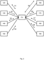
- Fig. 2 shows the control unit CU communicatively coupled to other units according to one or more embodiments of the present disclosure.
- the control unit CU is configured to send or receive control signals S1-S8 to/from the units 120-190 described in relation to Fig. 1 .
- the units 120-190 may send information to the control unit CU and receive information or commands from the control unit CU.
- control unit CU controls rollers comprised in the folding unit 180 by individually controlling rotational position and/or material velocity and/or angular velocity of rollers in the folding unit 180. Control of rollers over time is further described in relation to Fig. 9 .
- the control unit CU is further described in relation to fig. 7 .
- an adaptable folding unit 180 is provided. Distances between grippers and respective infeed plates may be adjusted.
- Fig. 3 illustrates details of a folding unit 180 according to one or more embodiments of the present disclosure.
- Fig. 3 shows a side view of the folding unit 180, without supports or frame holding the rollers for illustrative purposes.
- the folding unit 180 is configured to produce wipes, or more precise stacks of folded wipes 192 from the material 110.
- the folding unit comprises two or more folding rollers 350, 360 configured to receive the material 110 and generate wipes or stacks of wipes 192.
- Each folding roller 350, 360 comprises a hub 301, 302, wherein the hub 301, 302 comprises one or more grippers 331, 332, 341, 342 configured to grip and release the material 110.
- Each hub 301, 302 rotates around a respective center axis or longitudinal axis (not shown) in a rotational direction RD1, RD2 illustrated by the curved arrows.
- the folding unit further comprises one or more infeed plates 321, 322, 323, 324 configured to feed the material 110 to the one or more grippers 331, 332, 341, 342.
- the infeed plates of the first roller 350 feeds the material 110 to respective grippers on the second roller 360.
- infeed plate 321 of the first roller 350 feeds material to a respective gripper 342 on the second roller 360.
- infeed plate 323 of the second roller 360 feeds material to a respective gripper 332 of the first roller 350.
- the respective gripper 331, 332, 341, 342 then typically holds the material 110 during a certain rotation of the roller 350, 360, and then releases the material 110 at a determined point or rotation of the respective roller 350, 360, e.g., before or at the time when the material is gripped by the other roller.
- the gripper typically holds the material for long enough to draw material corresponding to a desired width w, as further described in relation to Fig. 6A and Fig. 6B .
- Fig. 3 illustrates how a gripper 331 has released the material 110.
- the material is folded in alternating directions effectively forming a zig-zag pattern as further described in Fig. 6A-B and Fig. 11A-C.
- each roller further comprises intermediate elements 311-318 forming the outer surface on which the material rests during rotation of the folding rollers 350, 360.
- a first infeed plate 322 on a first roller 350 protrudes from the outer surface of the respective roller 350, and as the roller/s rotate, in a respective rotational direction RD1, RD2.
- the first infeed plate 322 feeds/pushes the material 110 to a respective first gripper 341, which is controlled to grip the material 110.
- the roller 360 is then controlled to rotate a certain amount, corresponding to or in proportion to the width w of the stack, shown in relation to Fig. 6 and Fig. 6B .
- a second infeed plate 323 on the second roller 360 protrudes from the outer surface of the second roller, and as the roller/s rotate the second infeed plate 323 feeds/pushes the material 110 to a respective second gripper 332.
- the rollers 350, 360 of the folding unit 180 are provided with controllable actuators, such as servo motors, by which rotational position and/or angular velocity and/or material velocity and/or force between rollers may be controlled.
- the actuators may be integrated with the supports or frame which holds the rollers 350, 360, e.g., as a direct drive coupled to the rollers 350, 360. Control of the actuators is further described in relation to Fig. 8 and Fig. 9 . Control of rollers using actuators are well known in the art, an any suitable drive system may be used, for example direct drive, belt drive or chain drive.
- an adaptable folding unit 180 is provided and is configured to produce folded wipes 191 and/or stacks of folded wipes 192 from material 110.
- the folding unit 180 comprises: two or more folding rollers 350, 360 configured to receive a section of the material 110 and generate stacks of folded wipes 192 having an adaptable format.
- Each folding roller 350, 360 comprises a hub 301, 302, wherein the hub 301, 302 comprises one or more grippers 331, 332, 341, 342 configured to grip and release the material 110, and one or more infeed plates 321, 322, 323, 324 configured to feed the material 110 to the one or more grippers 331, 332, 341, 342.
- Positions of the one or more infeed plates 321, 322, 323, 324 are configured to be adjustable in relation to positions of the one or more grippers 331, 332, 341, 342, on the same roller 350, 360.
- Distances D1, D2 between the one or more grippers 331, 332, 341, 342 and a respective one or more infeed plates 321, 322, 323, 324 adapts a width w of the generated folded wipes 191 and/or stacks of wipes 192. In this context the distance is calculated from a gripper to a respective infeed plate in the machine direction and/or path direction.
- the present disclosure can adjust the distances D1, D2 between the one or more grippers 331, 332, 341, 342 and a respective one or more infeed plates 321, 322, 323, 324 to produce different formats of stacks and/or the wipes comprised by the stack.
- the machine is adapted to produce stacks of a different format by attaching surface modules to the rollers 350, 360 and by adjusting the movement of the rollers 350, 360 depending on the configuration of the surface modules.
- the configuration of the surface modules may be indicated by a user or detected by sensors, e.g., by detecting a Radio-frequency identification, RFID, tag. This effectively makes reconfiguration of the machine easier, quicker, and cheaper than replacing entire rollers, therefore resulting in a smaller and more flexible machine.
- the distance between the one or more grippers 331, 332, 341, 342 and a respective one or more infeed plates 321, 322, 323, 324 are adapted by mounting selected surface modules, where different surface modules have different distances between the infeed plate and a respective gripper.
- the surface module can then be identified by the control unit as described in the previous paragraph.
- the control unit CU can then adapt control of the rollers 350, 360 based on and associated distance between the infeed plate and a respective gripper, e.g., derived from the identity of the surface module.
- the distances D1, D2 between the one or more grippers 331, 332, 341, 342 and a respective one or more infeed plates 321, 322, 323, 324 is adapted by switching or swapping between different surface modules.
- Each surface module has a discrete or fixed distance between the one or more infeed plates 321, 322, 323, 324 and a respective one or more grippers 331, 332, 341, 342.
- Fig. 4 illustrates further details of a folding unit 180 provided with surface modules 410, 420 according to one or more embodiments of the present disclosure.
- the one or more infeed plates 321, 322, 323, 324 and optionally the intermediate elements 311-318 are integrated into surface modules releasably attached to a respective hub 301, 302.
- Each hub 301, 302 of the folding unit 180 comprises one or more grippers 331, 332, 341, 342.
- the one or more grippers 331, 332, 341, 342 are controlled by actuators, e.g., mechanical actuators, electrical actuators or pneumatical actuators.
- the actuators control the one or more grippers 331, 332, 341, 342 between open positions where the material is released, and closed positions where the material 110 is gripped.
- Each hub 301, 302 of the folding unit 180 is releasably attached to the one or more surface modules 410, 420 or vice versa.
- Each surface module 410, 420 comprises one or more one or more infeed plates 321, 322, 323, 324 and optionally also the intermediate elements 311-318 forming the outer surface of the rollers.
- the one or more infeed plates 321, 322, 323, 324 are mounted on a surface module 410, 420, wherein the surface module is configured to be releasably attached to the hub 301, 302.
- the machine is adapted by attaching different surface modules or surface modules to the rollers 350, 360 and by adjusting control of the movement of the rollers 350, 360 depending on the configuration of the surface modules.
- the configuration of the surface modules may be indicated by a user or detected by sensors, e.g., by detecting a Radio-frequency identification, RFID, tag. This effectively makes reconfiguration of the machine easier, quicker, and cheaper than replacing entire rollers, therefore resulting a smaller and more flexible machine.
- the configuration of the surface modules effectively adapts the distance along the outer surface/along the path between infeed plates and grippers on the respective roller 350/360.
- the distance between the one or more grippers 331, 332, 341, 342 and a respective one or more infeed plates 321, 322, 323, 324 are adapted moving and/or locking infeed plates and respective grippers to a desired position.
- the distance between the one or more grippers 331, 332, 341, 342 and a respective one or more infeed plates 321, 322, 323, 324 can be adjusted continuously.
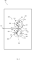
- Fig. 5 illustrates further details of a folding unit 180 provided with movable infeed plates 321, 322, 323, 324 according to one or more embodiments of the present disclosure.
- the one or more infeed plates 321, 322, 323, 324 are arranged as parts of the hub 301, 302 and are arranged movable in relation to the respective one or more grippers 331, 332.
- the infeed plates 321, 322, 323, 324 are movable along the outer surface of the rollers 350, 360 and around the center axis of the roller to allow the distance, along the outer surface, between the infeed plates 321, 322, 323, 324 and respective grippers 331, 332, 341, 342 to match a desired width w of the wipes.
- each of the one or more infeed plates 321, 322, 323, 324 are provided with a respective locking arrangement configured to lock the respective infeed plates in a position on the hub 301, 302.
- the locking arrangement may e.g., be locking screws or nuts locking the infeed plates 321, 322, 323, 324 to a position. Any other suitable locking arrangement may be used.
- Each hub 301, 302 of the folding unit 180 comprises one or more grippers 331, 332, 341, 342.
- the one or more grippers 331, 332, 341, 342 are controlled by actuators, e.g., mechanical actuators, electrical actuators or pneumatical actuators.
- the actuators control the one or more grippers 331, 332, 341, 342 between open positions and closed positions where the material is gripped or released.
- Fig. 5 the bidirectional arrows illustrate how the one or more infeed plates 321, 322, 323, 324 are arranged movable along the outer surface in relation to the respective one or more grippers 331, 332.
- the infeed plates 321, 322, 323, 324 are moved to a desired position, and control of the actuators is changed by which rotational position and/or angular velocity of the rollers 350, 360 is adapted to the new configuration of the machine. Control of the actuators is further described in relation to Fig. 8 and Fig. 9 .
- the configuration of the surface modules may be indicated by a user or detected by sensors. This effectively makes reconfiguration of the machine easier, quicker, and cheaper than replacing entire rollers, therefore resulting in a smaller and more flexible machine.
- Fig. 6A shows a side view of a stack of folded wipes 192 according to one or more embodiments of the present disclosure.
- the stack of folded wipes 192 comprises continuous material/web provided with or using perforations.
- the stack 192 comprises perforations illustrated by the thicker vertical lines on the right-hand side of the stack 192.
- the material 110 is folded across/orthogonal to the length direction of the material with a particular width or distance between folds w.
- the material is folded in alternating directions and forms a zig-zag pattern of folded wipes.
- any suitable folding pattern may be used as such as a V-folded, Z-folded, or M-folded configuration or any other folding pattern well known to those skilled in the art. Folding patterns are further described in relation to Fig. 10A-C .
- Each stack of folded wipes 192 typically comprises a selected number N of wipes that forms the stack of folded wipes 192.
- the number N for pop-up wipes is typically 2 wipes or more, where adjacent wipes can be separated by breaking then perforation between them.
- Fig. 6B shows a top view of a stack of folded wipes 192 according to one or more embodiments of the present disclosure.
- the width of the stack w as well as the length of the stack I is shown.
- the selected number N of wipes that forms the stack of folded wipes 192 is also shown.
- the material 110 is folded across/orthogonal to the length direction of the material with a particular width or distance between folds w.
- a perforation is positioned between each wipe at a distance d from the outer edge of the stack/from the fold. Depending on the container used, this distance may differ, although the perforation is typically arranged along a center w/2 of each wipe, or in the middle of folds, at least for the wipe on the top of the pile. The distance d may vary for each wipe without departing from the present disclosure. The positioning of perforations is further described in relation to Fig. 10A-C .
- Fig. 7 shows the control unit 700 according to one or more embodiments of the present disclosure.
- the control unit 700 may be in the form of e.g., an Electronic Control unit, a server, an on-board computer, a stationary computing device, a laptop computer, a tablet computer, a handheld computer, a wrist-worn computer, a smart watch, a smartphone, or a smart TV.
- the control unit 700 may comprise a processor/processing circuitry 712, optionally communicatively coupled to a communications interface 704, e.g., a transceiver configured for wired or wireless communication.
- the processing circuitry 712 may be any of a selection of processing circuitry and/or a central processing unit and/or processor modules and/or multiple processors configured to cooperate with each-other.
- the unit 700 may further comprise a memory 715.
- the memory 715 may e.g., comprise a selection of a hard RAM, disk drive, a floppy disk drive, a flash drive or other removable or fixed media drive or any other suitable memory known in the art.
- the memory 715 may contain instructions executable by the processing circuitry to perform any of the steps or methods described herein.
- the processing circuitry 712 may optionally be communicatively coupled to a selection of any of the communications interface 704, the memory 715, one or more sensors, such as sensors measuring rotational position and/or angular velocity of the rollers 350, 360 and/or sensors measuring distance between grippers and infeed plates.
- the control unit 700 may be configured to send/receive control signals directly to any of the above-mentioned units or to external nodes. E.g., to send control signals to the holder 111 of the material.
- the communications interface 704 such as a wired network adapter and/or a wireless network adaptor, may be configured to send and/or receive data values or parameters as a signal to or from the processing circuitry 712 to or from other external nodes. E.g., rotational position of rollers. In an embodiment, the communications interface 704 communicates directly to external nodes.
- control unit 700 may further comprise an input device 717, configured to receive input or indications from a user and send a user input signal indicative of the user input or indications to the processing circuitry 712.
- control unit 700 may further comprise a display 718 configured to receive a display signal indicative of rendered objects, such as text or graphical user input objects, from the processing circuitry 712 and to display the received signal as objects, such as text or graphical user input objects.
- a display signal indicative of rendered objects such as text or graphical user input objects
- the display 718 is integrated with the user input device 717 and is configured to receive a display signal indicative of rendered objects, such as text or graphical user input objects, from the processing circuitry 712 and to display the received signal as objects, such as text or graphical user input objects, and/or configured to receive input or indications from a user and send a user-input signal indicative of the user input or indications to the processing circuitry 712.
- a display signal indicative of rendered objects such as text or graphical user input objects
- control unit 700 may further comprise and/or be coupled to one or more additional sensors (not shown in the figure) configured to receive and/or obtain and/or measure physical properties pertaining to the machine 100 and send one or more sensor signals indicative of the physical properties of the machine 100 to the processing circuitry 712.
- additional sensors not shown in the figure
- the processing circuitry 712 is further communicatively coupled to the communications interface 704 and/or the input device 717 and/or the display 718 and/or the sensors and/or the additional sensors and/or any of the units described herein.
- control unit 700 may comprise the necessary communication capabilities in the form of e.g., functions, means, units, elements, etc., for performing the present solution.
- means, units, elements and functions are: processors, memory, buffers, control logic, encoders, decoders, rate matchers, de-rate matchers, mapping units, multipliers, decision units, selecting units, switches, modulators, demodulators, inputs, outputs, antennas, amplifiers, receiver units, transmitter units, DSPs, MSDs, TCM encoder, TCM decoder, power supply units, power feeders, communication interfaces, communication protocols, etc. which are suitably arranged together for performing the present solution.
- processing circuitry and/or processing means of the present disclosure may comprise one or more instances of processing circuitry, processor modules and multiple processors configured to cooperate with each-other, Central Processing Unit (CPU), a processing unit, a processing circuit, a processor, an Application Specific Integrated Circuit (ASIC), a microprocessor, a Field-Programmable Gate Array (FPGA) or other processing logic that may interpret and execute instructions.
- CPU Central Processing Unit
- ASIC Application Specific Integrated Circuit
- FPGA Field-Programmable Gate Array
- the expression "processing circuitry” and/or “processing means” may thus represent a processing circuitry comprising a plurality of processing circuits, such as, e.g., any, some or all of the ones mentioned above.
- the processing means may further perform data processing functions for inputting, outputting, and processing of data comprising data buffering and device control functions, such as user interface control, or the like.
- Fig. 8A shows control of rollers in a folding unit according to one or more embodiments of the present disclosure.
- the rollers 350, 360 of the folding unit 180 are shown in a side view, with the material passing through the folding unit 180 from the left to the right in Fig. 8A .
- the configuration of the rollers 350, 360 is associated with distances D1.
- D2 between the infeed plates and grippers on each roller 350, 360 e.g., derived from the identity of the surface module.
- This association may e.g., be stored in and retrieved from a database, entered by a user via an input device/interface of the control unit CU or otherwise retrieved/received from a node via a communication network.
- Fig. 8A-D the configuration of the rollers 350, 360 is two grippers and two infeed plates on each of the rollers 350, 360. Any number of grippers and infeed plates may be considered.
- the diameter of the outer surface of the rollers is 200 millimeters.
- the angular separation between grippers and infeed plates is alternating between 60 degrees and 120 degrees. The width of the stack can then be derived as further explained in relation to Fig. 9 .
- a first distance D1 along the outer surface of the first roller 350 from a first gripper 331 to a first infeed plate 321 is different from a second distance D2 along the outer surface of the second roller 360 from a first infeed plate 323 to the first infeed plate 341.
- the control unit CU determines characteristics of the rollers 350, 360, the desired characteristics of wipes and/or stack and/or the positions of grippers and infeed plates, and can then control the rollers 350, 360, accordingly, as further described in relation to Fig. 9 .
- An example of characteristics of the rollers 350, 360 may be circumference of the outer surface and distances between the infeed plates and grippers, either as angular separation or as absolute distance along the outer surface of the respective roller 350, 360.
- An example of characteristics of stacks is desired stack width w, as further described in relation to Fig. 6A-B .
- An example of characteristics of wipes is length of the wipe, e.g., distance between perforations in the length direction of the material.
- the rollers 350, 360 of the folding unit 180 are provided with controllable actuators, such as servo motors, by which rotational position and/or material velocity and/or angular velocity and/or force between rollers may be determined and/or controlled.
- the actuators may be integrated with the supports or frame which holds the rollers 350, 360, e.g., as a direct drive coupled to the rollers 350, 360.
- the first roller 350 of the folding unit 180 is rotating at a first angular velocity of ⁇ -350 in a counterclockwise direction, as indicated by the arrow.
- the second roller 350 of the folding unit 180 is rotating at a second angular velocity of ⁇ -360 in a clockwise direction, as indicated by the arrow.
- the first angular velocity of ⁇ -350 and the second angular velocity of ⁇ -360 are controlled to vary over time or dependent on time, as further illustrated in relation to figure 9 .
- the first angular velocity of ⁇ -350 and/or the second angular velocity of ⁇ -360 are stabilizing to the same angular velocity.
- the first and second roller 350, 360 are moving almost at the same angular velocity, but in opposite directions.
- the first roller 350 and second roller 360 each have a rotational position corresponding to a moment before an infeed plate of the second roller 360 starts pushing the material 110 into a gripper in the first roller 350.
- a gripper 342 in the second roller 360 is still holding the material 110.
- Fig. 8B shows control of rollers in a folding unit according to one or more embodiments of the present disclosure.
- the first roller 350 of the folding unit 180 is rotating at a first angular velocity of ⁇ -350 in a counterclockwise direction, as indicated by the arrow.
- the second roller 350 of the folding unit 180 is rotating at a second angular velocity of ⁇ -360 in a clockwise direction, as indicated by the arrow.
- the first angular velocity of ⁇ -350 and the second angular velocity of ⁇ -360 are controlled to vary over time or dependent on time, as further illustrated in relation to figure 9 .
- the first roller 350 and second roller 360 each have a rotational position corresponding to a moment when an infeed plate of the second roller 360 pushes the material 110 into the gripper in the first roller 350.
- the gripper in the first roller 350 is then controlled to grip the material 110, either at the point in time TB or adjacent to the point in time TB.
- the rotational position of the first roller 350 and first gripper 331 is synchronized to a rotational position of the second roller 360 and the first infeed plate 323.
- Fig. 8C shows control of rollers in a folding unit according to one or more embodiments of the present disclosure.
- the first roller 350 of the folding unit 180 is rotating at a first angular velocity of ⁇ -350 in a counterclockwise direction, as indicated by the arrow.
- the second roller 350 of the folding unit 180 is rotating at a second angular velocity of ⁇ -360 in a clockwise direction, as indicated by the arrow.
- the first angular velocity of ⁇ -350 and the second angular velocity of ⁇ -360 are controlled to vary over time or dependent on time, as further illustrated in relation to figure 9 .
- the first angular velocity of ⁇ -350 and the second angular velocity of ⁇ -360 are equal.
- the first and second roller 350, 360 are moving at the same angular velocity, but in opposite directions.
- the first roller 350 and second roller 360 each have a rotational position corresponding to a moment when an infeed plate of the first roller 350 pushes the material 110 into the gripper in the second roller 360.
- the gripper 341 is then controlled to grip the material 110 either at the point in time TC or adjacent to the point in time TC.
- the rotational position of the first roller 350 and second infeed plate 321 is synchronized to a rotational position of the second roller 360 and the second gripper 341.
- the second roller 360 has rotated more than the first roller 350 to synchronize infeed plate 321 and gripper 341.
- Fig. 8D shows control of rollers in a folding unit according to one or more embodiments of the present disclosure.
- the first roller 350 of the folding unit 180 is rotating at a first angular velocity of ⁇ -350 in a counterclockwise direction, as indicated by the arrow.
- the second roller 350 of the folding unit 180 is rotating at a second angular velocity of ⁇ -360 in a clockwise direction, as indicated by the arrow.
- the first angular velocity of ⁇ -350 and the second angular velocity of ⁇ -360 are controlled to vary over time or dependent on time, as further illustrated in relation to figure 9 .
- the first roller 350 and second roller 360 each have a rotational position corresponding to a moment when an infeed plate 324 of the second roller 360 pushes the material 110 into the gripper 332 in the first roller 350.
- the gripper 332 in the first roller 350 is then controlled to grip the material 110 either at the point in time TD or adjacent to the point in time TD.
- the rotational position of the first roller 350 and gripper 332 is synchronized to a rotational position of the second roller 360 and infeed plate 324.
- the points in time TA, TB, TC and TD are subsequent in time and are repeated dependent on the desired number N of wipes and/or number of folds that forms a stack of folded wipes 192.
- control unit CU adapts control of the actuators controlling the rollers 350, 360.
- the actuators controlling the rollers 350, 360 As the distances between grippers and respective infeed plates differ on the rollers, and the material 110 moves at a relatively constant velocity, the movement of the rollers 350, 360 must vary over time to synchronize positions of grippers and respective infeed plates.
- the variation of rotation over time is illustrated.
- the first roller 350 is controlled to a higher angular velocity ⁇ -350 in relation to the angular velocity ⁇ -360 of the second roller 360.
- the angular velocity of both the rollers 350, 360 are controlled to be almost the same. I.e., both the rollers 350, 360 move at similar angular velocity around respective center axis. This continues until the gripper 331 grips the material 110.
- the second roller 360 is controlled to a higher angular velocity ⁇ -360 in relation to the angular velocity ⁇ -350 of the first roller 350.
- both the rollers 350, 360 are controlled to be the same. I.e., both the rollers 350, 360 move at the same angular velocity around respective center axis. This continues until the gripper 341 grips the material 110. This control of rollers 350, 360 is then repeated for any number of desired folds.
- the material is folded in alternating directions effectively forming a zig-zag pattern as further described in Fig. 6AB and Fig. 11A-C.
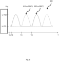
- Fig. 9 schematically illustrates control of angular velocity ⁇ -350, ⁇ -360 of rollers over time according to one or more embodiments of the present disclosure.
- Fig. 9 illustrates one example of a relation between angular velocity ⁇ and time T in a diagram 900 used by the control unit CU.
- the diagram 900 may e.g., be represented as data in a look-up table LUT.
- the rollers of the folding unit 180 are controlled at least sometimes to different angular velocities 910/ ⁇ -350, 920/ ⁇ -360 as a function of time T to ensure synchronization in rotational positions of feeder plates and respective grippers.
- the different angular velocities may in one embodiment be derived using knowledge of distance between infeed plates and respective grippers along the outer surface of on which the material 110 rest upon during rotation of the folding roller 350, 360.
- this control to different angular velocity varies between a relatively high angular velocity ⁇ -max and relatively low angular velocity ⁇ -min.
- the low angular velocity ⁇ -min is substantially the same as the material velocity of material being fed to the machine.
- the angular velocity of rollers cannot be changed instantaneously, e.g., due to inertia effects, the angular velocity needs to be ramped up/down according to some suitable method.
- the present disclosure is not limited to the ramping method illustrated in Fig. 9 , and any suitable ramping method that achieves synchronization in rotational positions of feeder plates and grippers may be used.
- control unit determines characteristics of the rollers 350, 360 such as diameter of the outer surface of the rollers, e.g., 200 millimeters. Further each roller is provided with two grippers and two feeder plates.
- L is the distance between a gripper and a feeder plate along the outer surface of roller
- ⁇ is angular separation in degrees between a gripper and a feeder plate around the center axis of the roller and r is the radius of the roller.
- the longer distance L2 is double the shorter distance L1.
- the second roller 360 could just rotate at double the speed compared to the first roller 350, in reality the angular velocity must be ramped up/down as illustrated in Fig. 9 .
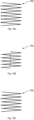
- Fig. 10A-C shows side views from the side of the stack 192 or from a direction orthogonal to the length direction of the material.
- Fig. 10A illustrates a V-folding pattern.
- Fig. 10A the material is folded in alternating directions and the perforation is located at the fold on the left hand of the stack shown in the figure.
- Each wipe in the stack, defined by the perforations, is provided with a single fold, and forms a v-folded wipe.
- Fig. 10B illustrates a Z-folding pattern.
- Fig. 10B the material is folded in alternating directions and the perforation is located at the center of the stack shown in the figure.
- Each wipe in the stack, defined by the perforations, is provided with two folds in alternating directions and forms a z-folded wipe.
- Fig. 10C illustrates an M-folding pattern.
- the material is folded in alternating directions and the perforation is located at every second fold on the left hand of the stack shown in the figure.
- Each wipe in the stack, defined by the perforations, is provided with three folds in alternating directions, and forms an M-folded wipe.
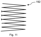
- Fig. 11 illustrates a stack comprising wipes having multiple formats.
- the produced stack 192 comprises a first wipe of length 4 x w, two shorter wipes of length 2 x w and a wipe of length 6 x w.
- This may also be referred to as a care pack, where wipes forming part of the continuous material are arranged in an order foreseen by a workflow of the user.
- Fig 12 shows a flowchart for a method 1200 according to one or more embodiments of the present disclosure.
- the method is performed by the control unit CU described herein.
- the method is provided for producing wipes, in particular pop-up wipes or wipes with pop-up functionality, performed by a machine 100 configured to produce stacks of folded wipes 192 from material 110.
- the material 110 is threaded along a path 112 through the machine 100.
- the method comprises: Step 1210: obtaining predetermined characteristics.
- the predetermined characteristics may e.g., be obtained by retrieving the predetermined characteristics by the control unit CU from a database, from retrieving input by a user via an input device/interface or any other suitable means.
- the predetermined characteristics comprises a selection of characteristics of the rollers 350, 360, characteristics of desired wipes and characteristics of desired stacks 192.
- the characteristics of the rollers 350, 360 are indicative of distances between grippers 331, 332, 341, 342 and respective infeed plates 321, 322, 323, 324, as described in relation to fig. 8A-D .
- the characteristics of desired wipes may be indicative of the combination of formats of wipes shown in relation to Fig. 11 .
- the characteristics of desired stacks may be indicative of the width w, as further described in relation to Fig. 6A-B .
- Step 1220 controlling angular velocity ⁇ -350, ⁇ -360 of rollers 350, 360 comprised in the folding unit 180 dependent on the predetermined characteristics.
- An example of controlling the angular velocity of rollers 350, 360 is further described in relation to Fig. 9 .
- the angular velocity is controlled between a maximum angular velocity ⁇ -max and a minimum angular velocity ⁇ -min dependent on the characteristics of the rollers 350, 360.
- the characteristics of the rollers 350, 360 are indicative of distances between grippers 331, 332, 341, 342 and respective infeed plates 321, 322, 323, 324, and the angular velocity is controlled in proportion to the predetermined characteristics.
- controlling the angular velocity is controlled in proportion to or dependent on the predetermined characteristics comprises:
- controlling angular velocity ⁇ -350, ⁇ -360 of rollers 350, 360 comprises controlling the first roller 350 to a relatively high angular velocity ⁇ -max and controlling the second roller 360 to a relatively low angular velocity ⁇ -min, or If the first distance D1 is smaller/less than the second distance D2, controlling angular velocity ⁇ -350, ⁇ -360 of rollers 350, 360 comprises controlling the first roller 350 to a relatively low angular velocity ⁇ -min and controlling the second roller 360 to a relatively high angular velocity ⁇ -max.
- the synchronized gripper is then controlled to grip the material 110 for a period of time allowing the material to advance a distance w before releasing the material again.
- controlling angular velocity ⁇ -350, ⁇ -360 of rollers 350, 360 comprises controlling in a ramp-up phase and a stationary phase, or controlling in a ramp-down phase and stationary phase.
- a roller being controlled from the relatively low angular velocity ⁇ -min to the relatively high angular velocity ⁇ -max will typically be controlled in a ramp-up phase in which the angular velocity is increased and a stationary phase where the relatively high angular velocity ⁇ -max is maintained.
- a roller being controlled from the relatively high angular velocity ⁇ -max to the relatively low angular velocity ⁇ -min will typically be controlled in a ramp-down phase in which the angular velocity is increased and a stationary phase where the relatively low angular velocity ⁇ -max is maintained.
- the advantage is that complexity is reduced when changing production to stacks or wipes having a different format by easily adjustable positions of the one or more infeed plates 321, 322 in relation to respective grippers 331, 332 and dynamic adaption of the control of rollers.
- a further advantage is that single direction folded wipes and multiple direction folded wipes can be produced in the same machine, e.g., wipes only folded across/orthogonal to the length/path direction of the material or wipes folded both in the length direction of the material and across/orthogonal to the length direction of the material.
- a further advantage is that multiple wipe formats can be combined in one stack, e.g., a care pack as illustrated in Fig. 11 . This is e.g., useful when producing a "care pack" with different wipes used in a cleaning operation. Yet a further advantage is that flexibility is increased, and complexity is reduced when producing wipes different formats and/or with different number of folding directions.
Landscapes
- Cleaning Implements For Floors, Carpets, Furniture, Walls, And The Like (AREA)
Applications Claiming Priority (1)
| Application Number | Priority Date | Filing Date | Title |
|---|---|---|---|
| SE2350017 | 2023-01-11 |
Publications (1)
| Publication Number | Publication Date |
|---|---|
| EP4400462A1 true EP4400462A1 (fr) | 2024-07-17 |
Family
ID=89573495
Family Applications (1)
| Application Number | Title | Priority Date | Filing Date |
|---|---|---|---|
| EP24150996.7A Pending EP4400462A1 (fr) | 2023-01-11 | 2024-01-09 | Machine et procédé conçues pour produire des piles de lingettes pliées |
Country Status (2)
| Country | Link |
|---|---|
| US (1) | US20240228221A1 (fr) |
| EP (1) | EP4400462A1 (fr) |
Citations (5)
| Publication number | Priority date | Publication date | Assignee | Title |
|---|---|---|---|---|
| DE4335048A1 (de) * | 1992-10-26 | 1994-04-28 | Heidelberger Druckmasch Ag | Schneide- und Faltmaschine für eine bedruckte durchgehende Papierbahn |
| US20030017282A1 (en) | 2001-07-23 | 2003-01-23 | Bae-Jou You | Plastic film wrap packaging box |
| WO2007135525A2 (fr) * | 2006-05-16 | 2007-11-29 | Omet S.R.L. | Dispositif perfectionné destiné au pliage de matériau souple |
| US8097326B2 (en) | 2008-10-27 | 2012-01-17 | Paper Converting Machine Company | Stack comprising multi-folded four panel sheets and folding boards therefor |
| WO2013115687A1 (fr) * | 2012-01-30 | 2013-08-08 | Sca Hygiene Products Ab | Empilement d'une matière en bande et son procédé de production |
-
2024
- 2024-01-09 EP EP24150996.7A patent/EP4400462A1/fr active Pending
- 2024-01-11 US US18/410,270 patent/US20240228221A1/en active Pending
Patent Citations (5)
| Publication number | Priority date | Publication date | Assignee | Title |
|---|---|---|---|---|
| DE4335048A1 (de) * | 1992-10-26 | 1994-04-28 | Heidelberger Druckmasch Ag | Schneide- und Faltmaschine für eine bedruckte durchgehende Papierbahn |
| US20030017282A1 (en) | 2001-07-23 | 2003-01-23 | Bae-Jou You | Plastic film wrap packaging box |
| WO2007135525A2 (fr) * | 2006-05-16 | 2007-11-29 | Omet S.R.L. | Dispositif perfectionné destiné au pliage de matériau souple |
| US8097326B2 (en) | 2008-10-27 | 2012-01-17 | Paper Converting Machine Company | Stack comprising multi-folded four panel sheets and folding boards therefor |
| WO2013115687A1 (fr) * | 2012-01-30 | 2013-08-08 | Sca Hygiene Products Ab | Empilement d'une matière en bande et son procédé de production |
Also Published As
| Publication number | Publication date |
|---|---|
| US20240228221A1 (en) | 2024-07-11 |
Similar Documents
| Publication | Publication Date | Title |
|---|---|---|
| EP0868998B1 (fr) | Machine de traitement de bandes à grande vitesse | |
| US5839688A (en) | Method and apparatus for producing a roll of bathroom tissue or kitchen toweling with a pattern being repeated between each pair of transverse perforations | |
| KR101809807B1 (ko) | 두개의 툴들 사이에서의 방사상 갭을 조정하기 위한 방법, 지지부를 변환시키기 위한 배열체, 그를 구비한 카세트, 유닛 및 기계 | |
| EP2751001A1 (fr) | Pile de produits d'hygiène pliés, et procédé et appareil de production de cette pile | |
| AU727285B2 (en) | Improved sheet products for use in a pop-up dispenser and method for forming | |
| EP3475204B1 (fr) | Système de traitement de bande doté de plusieurs dispositifs de pliage alimentés par un seul dispositif de manipulation de bande | |
| TW443963B (en) | Paper folding machine and high speed method for cutting a continuously fed web of paper | |
| US20240228221A1 (en) | Machine configured to produce stacks of folded wipes | |
| EP2394942B1 (fr) | Machine de pliage enchevêtré à pli unique dotée de la capacité de produire une serviette ou des produits de mouchoirs pliés | |
| TW396134B (en) | An apparatus for making product wrappers from heat-sealable paper | |
| EP1943092A2 (fr) | Plieuse haute vitesse | |
| EP4403504A1 (fr) | Machine et procédé correspondant conçues pour produire des piles de lingettes pliées | |
| RU2265570C2 (ru) | Способ сведения и отделки разных бумажных полотен и устройство для осуществления способа | |
| CA2659129C (fr) | Appareil pour perforer des supports imprimes ou gaufres | |
| JP7409795B2 (ja) | 逐次的に印刷された印刷用紙を選択的に横折りするための装置及び方法 | |
| US11891263B2 (en) | Interfolding machine | |
| WO2001058792A1 (fr) | Appareil et procede permettant de produire une unite d'emballage | |
| KR20210052215A (ko) | 전사장치 및 그 전사방법 | |
| JPH0671776B2 (ja) | 残余帯材を除去するための装置 | |
| US20010014643A1 (en) | Block formation system and method for controlling the folding of a block | |
| HK1236493A (en) | Stack of folded hygiene products and method and apparatus for producing same | |
| HK1236493A1 (en) | Stack of folded hygiene products and method and apparatus for producing same | |
| WO2008012764A2 (fr) | Procédé de perforation de supports imprimés ou gaufrés | |
| MXPA00002193A (en) | Method and apparatus for stacking pop-up towels |
Legal Events
| Date | Code | Title | Description |
|---|---|---|---|
| PUAI | Public reference made under article 153(3) epc to a published international application that has entered the european phase |
Free format text: ORIGINAL CODE: 0009012 |
|
| STAA | Information on the status of an ep patent application or granted ep patent |
Free format text: STATUS: THE APPLICATION HAS BEEN PUBLISHED |
|
| AK | Designated contracting states |
Kind code of ref document: A1 Designated state(s): AL AT BE BG CH CY CZ DE DK EE ES FI FR GB GR HR HU IE IS IT LI LT LU LV MC ME MK MT NL NO PL PT RO RS SE SI SK SM TR |
|
| STAA | Information on the status of an ep patent application or granted ep patent |
Free format text: STATUS: REQUEST FOR EXAMINATION WAS MADE |
|
| 17P | Request for examination filed |
Effective date: 20250114 |