EP4400721A1 - Compresseur - Google Patents
Compresseur Download PDFInfo
- Publication number
- EP4400721A1 EP4400721A1 EP22895401.2A EP22895401A EP4400721A1 EP 4400721 A1 EP4400721 A1 EP 4400721A1 EP 22895401 A EP22895401 A EP 22895401A EP 4400721 A1 EP4400721 A1 EP 4400721A1
- Authority
- EP
- European Patent Office
- Prior art keywords
- compression mechanism
- rotary shaft
- refrigerant
- rotor
- guide pipe
- Prior art date
- Legal status (The legal status is an assumption and is not a legal conclusion. Google has not performed a legal analysis and makes no representation as to the accuracy of the status listed.)
- Pending
Links
- 239000003507 refrigerant Substances 0.000 claims abstract description 74
- 230000006835 compression Effects 0.000 claims abstract description 71
- 238000007906 compression Methods 0.000 claims abstract description 71
- 230000000149 penetrating effect Effects 0.000 claims description 6
- 230000002093 peripheral effect Effects 0.000 description 5
- 238000000926 separation method Methods 0.000 description 5
- 230000000087 stabilizing effect Effects 0.000 description 5
- 230000000694 effects Effects 0.000 description 3
- 230000005484 gravity Effects 0.000 description 3
- 239000002184 metal Substances 0.000 description 3
- CURLTUGMZLYLDI-UHFFFAOYSA-N Carbon dioxide Chemical compound O=C=O CURLTUGMZLYLDI-UHFFFAOYSA-N 0.000 description 2
- 238000009434 installation Methods 0.000 description 2
- 230000004048 modification Effects 0.000 description 2
- 238000012986 modification Methods 0.000 description 2
- 238000011144 upstream manufacturing Methods 0.000 description 2
- 238000004804 winding Methods 0.000 description 2
- 229910002092 carbon dioxide Inorganic materials 0.000 description 1
- 239000001569 carbon dioxide Substances 0.000 description 1
- 238000007599 discharging Methods 0.000 description 1
- 230000001050 lubricating effect Effects 0.000 description 1
- 238000005461 lubrication Methods 0.000 description 1
- 238000004519 manufacturing process Methods 0.000 description 1
Images


Classifications
-
- F—MECHANICAL ENGINEERING; LIGHTING; HEATING; WEAPONS; BLASTING
- F04—POSITIVE - DISPLACEMENT MACHINES FOR LIQUIDS; PUMPS FOR LIQUIDS OR ELASTIC FLUIDS
- F04C—ROTARY-PISTON, OR OSCILLATING-PISTON, POSITIVE-DISPLACEMENT MACHINES FOR LIQUIDS; ROTARY-PISTON, OR OSCILLATING-PISTON, POSITIVE-DISPLACEMENT PUMPS
- F04C29/00—Component parts, details or accessories of pumps or pumping installations, not provided for in groups F04C18/00 - F04C28/00
- F04C29/12—Arrangements for admission or discharge of the working fluid, e.g. constructional features of the inlet or outlet
-
- F—MECHANICAL ENGINEERING; LIGHTING; HEATING; WEAPONS; BLASTING
- F04—POSITIVE - DISPLACEMENT MACHINES FOR LIQUIDS; PUMPS FOR LIQUIDS OR ELASTIC FLUIDS
- F04B—POSITIVE-DISPLACEMENT MACHINES FOR LIQUIDS; PUMPS
- F04B35/00—Piston pumps specially adapted for elastic fluids and characterised by the driving means to their working members, or by combination with, or adaptation to, specific driving engines or motors, not otherwise provided for
- F04B35/04—Piston pumps specially adapted for elastic fluids and characterised by the driving means to their working members, or by combination with, or adaptation to, specific driving engines or motors, not otherwise provided for the means being electric
-
- F—MECHANICAL ENGINEERING; LIGHTING; HEATING; WEAPONS; BLASTING
- F04—POSITIVE - DISPLACEMENT MACHINES FOR LIQUIDS; PUMPS FOR LIQUIDS OR ELASTIC FLUIDS
- F04B—POSITIVE-DISPLACEMENT MACHINES FOR LIQUIDS; PUMPS
- F04B39/00—Component parts, details, or accessories, of pumps or pumping systems specially adapted for elastic fluids, not otherwise provided for in, or of interest apart from, groups F04B25/00 - F04B37/00
- F04B39/12—Casings; Cylinders; Cylinder heads; Fluid connections
- F04B39/121—Casings
-
- F—MECHANICAL ENGINEERING; LIGHTING; HEATING; WEAPONS; BLASTING
- F04—POSITIVE - DISPLACEMENT MACHINES FOR LIQUIDS; PUMPS FOR LIQUIDS OR ELASTIC FLUIDS
- F04B—POSITIVE-DISPLACEMENT MACHINES FOR LIQUIDS; PUMPS
- F04B39/00—Component parts, details, or accessories, of pumps or pumping systems specially adapted for elastic fluids, not otherwise provided for in, or of interest apart from, groups F04B25/00 - F04B37/00
- F04B39/12—Casings; Cylinders; Cylinder heads; Fluid connections
- F04B39/123—Fluid connections
-
- F—MECHANICAL ENGINEERING; LIGHTING; HEATING; WEAPONS; BLASTING
- F04—POSITIVE - DISPLACEMENT MACHINES FOR LIQUIDS; PUMPS FOR LIQUIDS OR ELASTIC FLUIDS
- F04C—ROTARY-PISTON, OR OSCILLATING-PISTON, POSITIVE-DISPLACEMENT MACHINES FOR LIQUIDS; ROTARY-PISTON, OR OSCILLATING-PISTON, POSITIVE-DISPLACEMENT PUMPS
- F04C18/00—Rotary-piston pumps specially adapted for elastic fluids
- F04C18/02—Rotary-piston pumps specially adapted for elastic fluids of arcuate-engagement type, i.e. with circular translatory movement of co-operating members, each member having the same number of teeth or tooth-equivalents
- F04C18/0207—Rotary-piston pumps specially adapted for elastic fluids of arcuate-engagement type, i.e. with circular translatory movement of co-operating members, each member having the same number of teeth or tooth-equivalents both members having co-operating elements in spiral form
- F04C18/0215—Rotary-piston pumps specially adapted for elastic fluids of arcuate-engagement type, i.e. with circular translatory movement of co-operating members, each member having the same number of teeth or tooth-equivalents both members having co-operating elements in spiral form where only one member is moving
-
- F—MECHANICAL ENGINEERING; LIGHTING; HEATING; WEAPONS; BLASTING
- F04—POSITIVE - DISPLACEMENT MACHINES FOR LIQUIDS; PUMPS FOR LIQUIDS OR ELASTIC FLUIDS
- F04C—ROTARY-PISTON, OR OSCILLATING-PISTON, POSITIVE-DISPLACEMENT MACHINES FOR LIQUIDS; ROTARY-PISTON, OR OSCILLATING-PISTON, POSITIVE-DISPLACEMENT PUMPS
- F04C23/00—Combinations of two or more pumps, each being of rotary-piston or oscillating-piston type, specially adapted for elastic fluids; Pumping installations specially adapted for elastic fluids; Multi-stage pumps specially adapted for elastic fluids
- F04C23/005—Combinations of two or more pumps, each being of rotary-piston or oscillating-piston type, specially adapted for elastic fluids; Pumping installations specially adapted for elastic fluids; Multi-stage pumps specially adapted for elastic fluids of dissimilar working principle
-
- F—MECHANICAL ENGINEERING; LIGHTING; HEATING; WEAPONS; BLASTING
- F04—POSITIVE - DISPLACEMENT MACHINES FOR LIQUIDS; PUMPS FOR LIQUIDS OR ELASTIC FLUIDS
- F04C—ROTARY-PISTON, OR OSCILLATING-PISTON, POSITIVE-DISPLACEMENT MACHINES FOR LIQUIDS; ROTARY-PISTON, OR OSCILLATING-PISTON, POSITIVE-DISPLACEMENT PUMPS
- F04C23/00—Combinations of two or more pumps, each being of rotary-piston or oscillating-piston type, specially adapted for elastic fluids; Pumping installations specially adapted for elastic fluids; Multi-stage pumps specially adapted for elastic fluids
- F04C23/008—Hermetic pumps
-
- F—MECHANICAL ENGINEERING; LIGHTING; HEATING; WEAPONS; BLASTING
- F04—POSITIVE - DISPLACEMENT MACHINES FOR LIQUIDS; PUMPS FOR LIQUIDS OR ELASTIC FLUIDS
- F04C—ROTARY-PISTON, OR OSCILLATING-PISTON, POSITIVE-DISPLACEMENT MACHINES FOR LIQUIDS; ROTARY-PISTON, OR OSCILLATING-PISTON, POSITIVE-DISPLACEMENT PUMPS
- F04C18/00—Rotary-piston pumps specially adapted for elastic fluids
- F04C18/30—Rotary-piston pumps specially adapted for elastic fluids having the characteristics covered by two or more of groups F04C18/02, F04C18/08, F04C18/22, F04C18/24, F04C18/48, or having the characteristics covered by one of these groups together with some other type of movement between co-operating members
- F04C18/34—Rotary-piston pumps specially adapted for elastic fluids having the characteristics covered by two or more of groups F04C18/02, F04C18/08, F04C18/22, F04C18/24, F04C18/48, or having the characteristics covered by one of these groups together with some other type of movement between co-operating members having the movement defined in group F04C18/08 or F04C18/22 and relative reciprocation between the co-operating members
- F04C18/356—Rotary-piston pumps specially adapted for elastic fluids having the characteristics covered by two or more of groups F04C18/02, F04C18/08, F04C18/22, F04C18/24, F04C18/48, or having the characteristics covered by one of these groups together with some other type of movement between co-operating members having the movement defined in group F04C18/08 or F04C18/22 and relative reciprocation between the co-operating members with vanes reciprocating with respect to the outer member
- F04C18/3562—Rotary-piston pumps specially adapted for elastic fluids having the characteristics covered by two or more of groups F04C18/02, F04C18/08, F04C18/22, F04C18/24, F04C18/48, or having the characteristics covered by one of these groups together with some other type of movement between co-operating members having the movement defined in group F04C18/08 or F04C18/22 and relative reciprocation between the co-operating members with vanes reciprocating with respect to the outer member the inner and outer member being in contact along one line or continuous surfaces substantially parallel to the axis of rotation
Definitions
- a two-stage compressor including a rotary compression mechanism and a scroll compression mechanism in a housing is known.
- a refrigerant compressed by a rotary compression mechanism on a low-stage side is discharged into a housing, and the discharged refrigerant is further compressed by a scroll compression mechanism on a high-stage side.
- a motor that rotationally drives a rotary shaft is provided between the rotary compression mechanism on the low-stage side and the scroll compression mechanism on the high-stage side. For this reason, a through-hole for guiding the refrigerant discharged from the rotary compression mechanism to the scroll compression mechanism is formed in the motor.
- a funnel-shaped cover is provided above a lower bearing 32A provided above the rotary compression mechanism, and the refrigerant discharged from the rotary compression mechanism is caused to flow upward from the vicinity of the rotary shaft.
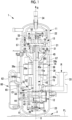
- a compressor 1 is used for an air conditioner and compresses a refrigerant R, which is, for example, a gas such as carbon dioxide, in two stages.
- the compressor 1 is fixed to an installation surface FL via leg portions 3.
- the compressor 1 includes a housing 11 and includes a rotary compression mechanism (low-stage-side compression mechanism) 12, a scroll compression mechanism (high-stage-side compression mechanism) 13, an electric motor 14, and a rotary shaft (rotary shaft portion) 15, which are provided inside the housing 11.
- the rotary shaft 15 is provided to extend vertically along an axis X inside the housing 11. An upper end (one end) side of the rotary shaft 15 is rotatably supported by an upper bearing 31. A lower end (other end) side of the rotary shaft 15 is rotatably supported by a lower bearing 32.
- the rotor 38 is provided with rotor passages (through-hole) 38a provided at a predetermined interval in a circumferential direction. Each rotor passage 38a penetrates the rotor 38 in a vertical direction (axis X direction). The refrigerant discharged from a rotary compression mechanism 12 flows upward through the rotor passages 38a.
- An oil separation plate (baffle plate) 38b is fixed to an upper portion of the rotor 38.
- the oil separation plate 38b has a circular plate shape and is disposed to extend in a horizontal direction. The oil separation plate 38b rotates around the axis X together with the rotor 38.
- an upper coil end 39b in which a winding is folded back is located at an upper portion of the stator 39, and a lower coil end 39c in which a winding is folded back is located at a lower portion of the stator 39.
- the electric motor 14 is connected to a power source via an inverter (not shown) and rotates the rotary shaft 15 with a variable frequency.
- the rotary compression mechanism 12 is provided on the lower end (other end) side of the rotary shaft 15 inside the housing 11.
- the rotary compression mechanism 12 is a two-cylinder mechanism in the present embodiment, and includes an eccentric shaft portion 41 provided in the rotary shaft 15, a rotor 42 fixed to the eccentric shaft portion 41 and rotating in a compression chamber C1 eccentrically with respect to the axis X as the rotary shaft 15 rotates, and a cylinder 44 in which the compression chamber C1 is formed.
- a scroll compression mechanism 13 is disposed above the electric motor 14 inside the housing 11.
- the scroll compression mechanism 13 includes a fixed scroll 51 fixed to the upper bearing 31, and an orbiting scroll 57 disposed below the fixed scroll 51 to face the fixed scroll 51.
- the fixed scroll 51 has an end plate 52 fixed to an upper surface of the upper bearing 31 and a fixed wrap 53 protruding downward from the end plate 52.
- a discharge hole 52a vertically penetrating the end plate 52 is formed in a central portion (vicinity of the axis X) of the end plate 52.
- the orbiting wrap 59 forms a compression chamber C2 for compressing the refrigerant R between the orbiting wrap 59 and the fixed wrap 53 by meshing with the fixed wrap 53.
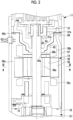
- An oil return pipe 67 that is in contact with an inner wall of the housing 11 and extends in a vertical direction is provided in the housing 11. As shown in Fig. 2 , an upper end (one end) of the oil return pipe 67 is fixed to the upper bearing 31 via a boss 68, and a lower end (other end) is provided to be located in the oil reservoir O1 in the lower portion of the housing 11. The lower end of the oil return pipe 67 is fixed to the inner wall of the housing 11 via a rod-shaped member 70.
- the rotor passages 38a are provided at a predetermined interval in the circumferential direction.
- the refrigerant discharged from a rotary compression mechanism 12 flows upward through the rotor passages 38a.
- the discharge valve is a valve provided at a discharge port (not shown) for discharging the refrigerant compressed by the rotary compression mechanism 12 to the discharge space S.
- a discharge port not shown
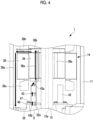
- the guide pipe 43 is provided above the rotary compression mechanism 12 and guides the refrigerant discharged from the rotary compression mechanism 12 to the rotor passage 38a.
- the guide pipe 43 is a cylindrical member formed in a linear shape.
- the guide pipe 43 extends linearly along a vertical direction (axis X direction).
- the guide pipe 43 extends to the vicinity of a lower end of the rotor 38.
- An upper end of the guide pipe 43 is located above a lower end of the lower coil end 39c.
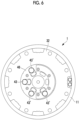
- the guide pipe 43 is disposed to overlap the rotor 38 when viewed in the axis X direction. Specifically, the guide pipe 43 is disposed to overlap the rotor passage 38a formed in the rotor 38 when viewed in the axis X direction. More specifically, the guide pipe 43 is disposed to overlap an opening in which a refrigerant outlet 43a is formed at a lower end of the rotor passage 38a.
- the compressor 1 having the above-described configuration operates as follows.
- the refrigerant evaporated in an evaporator (not shown) is sucked into the compressor 1 from the suction pipe 33 and is compressed by the rotary compression mechanism 12.
- the refrigerant compressed by the rotary compression mechanism 12 is discharged from the guide pipe 43 into the housing 11.
- the oil is separated from the refrigerant discharged from the discharge pipe 34 by an oil separator (not shown).
- the separated oil is returned to the housing 11 through the oil separator oil return pipe 65, and is stored in the oil reservoir O1.
- the oil stored in the oil reservoir O1 is sucked up by the oil pump 49, and is guided to the scroll compression mechanism 13 side through the oil supply hole 15a formed in the rotary shaft 15.
- the oil guided to the scroll compression mechanism 13 side is returned to the oil reservoir O1 on the lower side after lubricating a sliding portion such as a bearing portion of the upper bearing 31 and the bush 55.
- the oil after lubrication which is guided to the balance weight chamber 63, is guided to the oil return pipe 67 through the oil return hole 31a and the vertical hole 31b (refer to Fig. 2 ) formed in the upper bearing 31.
- Fig. 5 schematically shows the flow of the refrigerant and the oil formed by the cover 45.
- the flow of the refrigerant is indicated by a white arrow
- the flow of the oil is indicated by a black arrow.
- the refrigerant and the oil that have come out of the rotor passage 38a collide with the oil separation plate 38b and are guided in a radial direction about the axis X by a centrifugal force. Then, the oil having a larger specific gravity larger than the refrigerant collides with the inner wall of the housing 11 and flows downward by gravity. A part of the oil flows upward together with the refrigerant in a space between the inner wall of the housing 11 and the upper coil end 39b. The part of the oil that has ascended together with the refrigerant collides with an upper end of an outer periphery of the cover 45 (refer to Figs. 1 and 2 ), and then falls downward by gravity.
- the guide pipe 43 is disposed to overlap the rotor passage 38a formed in the rotor 38. As a result, a position of the guide pipe 43 becomes close to a position of the rotor passage 38a. Therefore, the refrigerant can be easily guided from the guide pipe 43 to the rotor passage 38a.
- the guide pipe 43 is a straight pipe.
- the present disclosure is not limited thereto.
- a guide pipe 43' of which an upper end portion is curved to a radial inner side (the rotor passage 38a side) may be used.
- the guide pipe 43' is curved such that the refrigerant outlet 43a is closer to the rotor passage 38a than the refrigerant inlet 43b when viewed in the axis X direction.
- the guide pipe is disposed to overlap the rotor.
- the position of the guide pipe becomes close to the position of the through-hole. Therefore, the refrigerant can be easily guided from the guide pipe to the through-hole.
- the guide pipe is disposed to overlap the through-hole when viewed in a direction of the longitudinal axis.
- the guide pipe is curved such that an upper end thereof provided with a refrigerant outlet (43a) through which the refrigerant is discharged is close to the through-hole when viewed in the direction of the longitudinal axis.
- the position of the refrigerant outlet through which the refrigerant is discharged is close to the position of the through-hole. Therefore, the refrigerant can be more easily guided from the guide pipe to the through-hole.
Landscapes
- Engineering & Computer Science (AREA)
- Mechanical Engineering (AREA)
- General Engineering & Computer Science (AREA)
- Applications Or Details Of Rotary Compressors (AREA)
- Compressor (AREA)
Applications Claiming Priority (2)
| Application Number | Priority Date | Filing Date | Title |
|---|---|---|---|
| JP2021189463A JP2023076188A (ja) | 2021-11-22 | 2021-11-22 | 圧縮機 |
| PCT/JP2022/040221 WO2023090118A1 (fr) | 2021-11-22 | 2022-10-27 | Compresseur |
Publications (2)
| Publication Number | Publication Date |
|---|---|
| EP4400721A1 true EP4400721A1 (fr) | 2024-07-17 |
| EP4400721A4 EP4400721A4 (fr) | 2024-12-18 |
Family
ID=86396752
Family Applications (1)
| Application Number | Title | Priority Date | Filing Date |
|---|---|---|---|
| EP22895401.2A Pending EP4400721A4 (fr) | 2021-11-22 | 2022-10-27 | Compresseur |
Country Status (3)
| Country | Link |
|---|---|
| EP (1) | EP4400721A4 (fr) |
| JP (1) | JP2023076188A (fr) |
| WO (1) | WO2023090118A1 (fr) |
Family Cites Families (4)
| Publication number | Priority date | Publication date | Assignee | Title |
|---|---|---|---|---|
| JP2009047039A (ja) * | 2007-08-17 | 2009-03-05 | Mitsubishi Heavy Ind Ltd | 多段圧縮機 |
| JP2010053778A (ja) * | 2008-08-28 | 2010-03-11 | Toshiba Carrier Corp | 密閉型圧縮機およびこれを用いた冷凍サイクル装置 |
| JP5709544B2 (ja) * | 2011-01-17 | 2015-04-30 | 三菱重工業株式会社 | 圧縮機 |
| JP6755114B2 (ja) | 2016-04-14 | 2020-09-16 | 三菱重工サーマルシステムズ株式会社 | 密閉型二段圧縮機 |
-
2021
- 2021-11-22 JP JP2021189463A patent/JP2023076188A/ja active Pending
-
2022
- 2022-10-27 EP EP22895401.2A patent/EP4400721A4/fr active Pending
- 2022-10-27 WO PCT/JP2022/040221 patent/WO2023090118A1/fr not_active Ceased
Also Published As
| Publication number | Publication date |
|---|---|
| JP2023076188A (ja) | 2023-06-01 |
| EP4400721A4 (fr) | 2024-12-18 |
| WO2023090118A1 (fr) | 2023-05-25 |
Similar Documents
| Publication | Publication Date | Title |
|---|---|---|
| EP2312164B1 (fr) | Compresseur à volutes | |
| EP2218914A2 (fr) | Machine à spirales | |
| US6428296B1 (en) | Horizontal scroll compressor having an oil injection fitting | |
| US20090136372A1 (en) | Open drive scroll compressor with lubrication system | |
| US20200003199A1 (en) | Compressor | |
| CN113950581A (zh) | 涡旋式压缩机 | |
| EP3575605B1 (fr) | Compresseur hermétique | |
| EP3584443B1 (fr) | Compresseur | |
| US5013225A (en) | Lubrication system for a scroll compressor | |
| EP4400721A1 (fr) | Compresseur | |
| JP4307945B2 (ja) | 横型ロータリコンプレッサ | |
| EP1764507A2 (fr) | Compresseur | |
| EP4400722B1 (fr) | Compresseur | |
| EP3409948B1 (fr) | Compresseur hermétique à deux étages | |
| EP4400716B1 (fr) | Compresseur | |
| JP2020045778A (ja) | 圧縮機 | |
| EP4621241A1 (fr) | Compresseur | |
| EP4400724A1 (fr) | Compresseur | |
| EP3992461B1 (fr) | Compresseur à spirale | |
| JP5540577B2 (ja) | スクロール圧縮機 | |
| EP3971420A1 (fr) | Compresseur et dispositif de réfrigération | |
| JP2004293380A (ja) | 横型ロータリコンプレッサ | |
| JP6711136B2 (ja) | スクロール圧縮機 | |
| JP2013241902A (ja) | オイルセパレータ付圧縮機 | |
| WO2026005009A1 (fr) | Compresseur |
Legal Events
| Date | Code | Title | Description |
|---|---|---|---|
| STAA | Information on the status of an ep patent application or granted ep patent |
Free format text: STATUS: THE INTERNATIONAL PUBLICATION HAS BEEN MADE |
|
| PUAI | Public reference made under article 153(3) epc to a published international application that has entered the european phase |
Free format text: ORIGINAL CODE: 0009012 |
|
| STAA | Information on the status of an ep patent application or granted ep patent |
Free format text: STATUS: REQUEST FOR EXAMINATION WAS MADE |
|
| 17P | Request for examination filed |
Effective date: 20240411 |
|
| AK | Designated contracting states |
Kind code of ref document: A1 Designated state(s): AL AT BE BG CH CY CZ DE DK EE ES FI FR GB GR HR HU IE IS IT LI LT LU LV MC ME MK MT NL NO PL PT RO RS SE SI SK SM TR |
|
| A4 | Supplementary search report drawn up and despatched |
Effective date: 20241118 |
|
| RIC1 | Information provided on ipc code assigned before grant |
Ipc: F04B 39/12 20060101ALI20241112BHEP Ipc: F04C 29/12 20060101ALI20241112BHEP Ipc: F04C 23/00 20060101AFI20241112BHEP |
|
| DAV | Request for validation of the european patent (deleted) | ||
| DAX | Request for extension of the european patent (deleted) |