EP4400733A1 - Composant coulissant - Google Patents
Composant coulissant Download PDFInfo
- Publication number
- EP4400733A1 EP4400733A1 EP24156603.3A EP24156603A EP4400733A1 EP 4400733 A1 EP4400733 A1 EP 4400733A1 EP 24156603 A EP24156603 A EP 24156603A EP 4400733 A1 EP4400733 A1 EP 4400733A1
- Authority
- EP
- European Patent Office
- Prior art keywords
- recessed portions
- outward
- seal ring
- inward
- land
- Prior art date
- Legal status (The legal status is an assumption and is not a legal conclusion. Google has not performed a legal analysis and makes no representation as to the accuracy of the status listed.)
- Pending
Links
Images




Classifications
-
- F—MECHANICAL ENGINEERING; LIGHTING; HEATING; WEAPONS; BLASTING
- F16—ENGINEERING ELEMENTS AND UNITS; GENERAL MEASURES FOR PRODUCING AND MAINTAINING EFFECTIVE FUNCTIONING OF MACHINES OR INSTALLATIONS; THERMAL INSULATION IN GENERAL
- F16C—SHAFTS; FLEXIBLE SHAFTS; ELEMENTS OR CRANKSHAFT MECHANISMS; ROTARY BODIES OTHER THAN GEARING ELEMENTS; BEARINGS
- F16C33/00—Parts of bearings; Special methods for making bearings or parts thereof
- F16C33/72—Sealings
- F16C33/74—Sealings of sliding-contact bearings
-
- F—MECHANICAL ENGINEERING; LIGHTING; HEATING; WEAPONS; BLASTING
- F16—ENGINEERING ELEMENTS AND UNITS; GENERAL MEASURES FOR PRODUCING AND MAINTAINING EFFECTIVE FUNCTIONING OF MACHINES OR INSTALLATIONS; THERMAL INSULATION IN GENERAL
- F16C—SHAFTS; FLEXIBLE SHAFTS; ELEMENTS OR CRANKSHAFT MECHANISMS; ROTARY BODIES OTHER THAN GEARING ELEMENTS; BEARINGS
- F16C17/00—Sliding-contact bearings for exclusively rotary movement
- F16C17/04—Sliding-contact bearings for exclusively rotary movement for axial load only
-
- F—MECHANICAL ENGINEERING; LIGHTING; HEATING; WEAPONS; BLASTING
- F16—ENGINEERING ELEMENTS AND UNITS; GENERAL MEASURES FOR PRODUCING AND MAINTAINING EFFECTIVE FUNCTIONING OF MACHINES OR INSTALLATIONS; THERMAL INSULATION IN GENERAL
- F16C—SHAFTS; FLEXIBLE SHAFTS; ELEMENTS OR CRANKSHAFT MECHANISMS; ROTARY BODIES OTHER THAN GEARING ELEMENTS; BEARINGS
- F16C17/00—Sliding-contact bearings for exclusively rotary movement
- F16C17/04—Sliding-contact bearings for exclusively rotary movement for axial load only
- F16C17/045—Sliding-contact bearings for exclusively rotary movement for axial load only with grooves in the bearing surface to generate hydrodynamic pressure, e.g. spiral groove thrust bearings
-
- F—MECHANICAL ENGINEERING; LIGHTING; HEATING; WEAPONS; BLASTING
- F16—ENGINEERING ELEMENTS AND UNITS; GENERAL MEASURES FOR PRODUCING AND MAINTAINING EFFECTIVE FUNCTIONING OF MACHINES OR INSTALLATIONS; THERMAL INSULATION IN GENERAL
- F16C—SHAFTS; FLEXIBLE SHAFTS; ELEMENTS OR CRANKSHAFT MECHANISMS; ROTARY BODIES OTHER THAN GEARING ELEMENTS; BEARINGS
- F16C33/00—Parts of bearings; Special methods for making bearings or parts thereof
- F16C33/02—Parts of sliding-contact bearings
- F16C33/04—Brasses; Bushes; Linings
- F16C33/06—Sliding surface mainly made of metal
- F16C33/10—Construction relative to lubrication
- F16C33/1025—Construction relative to lubrication with liquid, e.g. oil, as lubricant
- F16C33/106—Details of distribution or circulation inside the bearings, e.g. details of the bearing surfaces to affect flow or pressure of the liquid
- F16C33/1065—Grooves on a bearing surface for distributing or collecting the liquid
-
- F—MECHANICAL ENGINEERING; LIGHTING; HEATING; WEAPONS; BLASTING
- F16—ENGINEERING ELEMENTS AND UNITS; GENERAL MEASURES FOR PRODUCING AND MAINTAINING EFFECTIVE FUNCTIONING OF MACHINES OR INSTALLATIONS; THERMAL INSULATION IN GENERAL
- F16C—SHAFTS; FLEXIBLE SHAFTS; ELEMENTS OR CRANKSHAFT MECHANISMS; ROTARY BODIES OTHER THAN GEARING ELEMENTS; BEARINGS
- F16C33/00—Parts of bearings; Special methods for making bearings or parts thereof
- F16C33/02—Parts of sliding-contact bearings
- F16C33/04—Brasses; Bushes; Linings
- F16C33/06—Sliding surface mainly made of metal
- F16C33/10—Construction relative to lubrication
- F16C33/1025—Construction relative to lubrication with liquid, e.g. oil, as lubricant
- F16C33/106—Details of distribution or circulation inside the bearings, e.g. details of the bearing surfaces to affect flow or pressure of the liquid
- F16C33/107—Grooves for generating pressure
-
- F—MECHANICAL ENGINEERING; LIGHTING; HEATING; WEAPONS; BLASTING
- F16—ENGINEERING ELEMENTS AND UNITS; GENERAL MEASURES FOR PRODUCING AND MAINTAINING EFFECTIVE FUNCTIONING OF MACHINES OR INSTALLATIONS; THERMAL INSULATION IN GENERAL
- F16J—PISTONS; CYLINDERS; SEALINGS
- F16J15/00—Sealings
- F16J15/16—Sealings between relatively-moving surfaces
- F16J15/164—Sealings between relatively-moving surfaces the sealing action depending on movements; pressure difference, temperature or presence of leaking fluid
-
- F—MECHANICAL ENGINEERING; LIGHTING; HEATING; WEAPONS; BLASTING
- F16—ENGINEERING ELEMENTS AND UNITS; GENERAL MEASURES FOR PRODUCING AND MAINTAINING EFFECTIVE FUNCTIONING OF MACHINES OR INSTALLATIONS; THERMAL INSULATION IN GENERAL
- F16J—PISTONS; CYLINDERS; SEALINGS
- F16J15/00—Sealings
- F16J15/16—Sealings between relatively-moving surfaces
- F16J15/34—Sealings between relatively-moving surfaces with slip-ring pressed against a more or less radial face on one member
-
- F—MECHANICAL ENGINEERING; LIGHTING; HEATING; WEAPONS; BLASTING
- F16—ENGINEERING ELEMENTS AND UNITS; GENERAL MEASURES FOR PRODUCING AND MAINTAINING EFFECTIVE FUNCTIONING OF MACHINES OR INSTALLATIONS; THERMAL INSULATION IN GENERAL
- F16J—PISTONS; CYLINDERS; SEALINGS
- F16J15/00—Sealings
- F16J15/16—Sealings between relatively-moving surfaces
- F16J15/34—Sealings between relatively-moving surfaces with slip-ring pressed against a more or less radial face on one member
- F16J15/3404—Sealings between relatively-moving surfaces with slip-ring pressed against a more or less radial face on one member and characterised by parts or details relating to lubrication, cooling or venting of the seal
- F16J15/3408—Sealings between relatively-moving surfaces with slip-ring pressed against a more or less radial face on one member and characterised by parts or details relating to lubrication, cooling or venting of the seal at least one ring having an uneven slipping surface
- F16J15/3412—Sealings between relatively-moving surfaces with slip-ring pressed against a more or less radial face on one member and characterised by parts or details relating to lubrication, cooling or venting of the seal at least one ring having an uneven slipping surface with cavities
-
- F—MECHANICAL ENGINEERING; LIGHTING; HEATING; WEAPONS; BLASTING
- F16—ENGINEERING ELEMENTS AND UNITS; GENERAL MEASURES FOR PRODUCING AND MAINTAINING EFFECTIVE FUNCTIONING OF MACHINES OR INSTALLATIONS; THERMAL INSULATION IN GENERAL
- F16J—PISTONS; CYLINDERS; SEALINGS
- F16J15/00—Sealings
- F16J15/16—Sealings between relatively-moving surfaces
- F16J15/34—Sealings between relatively-moving surfaces with slip-ring pressed against a more or less radial face on one member
- F16J15/3404—Sealings between relatively-moving surfaces with slip-ring pressed against a more or less radial face on one member and characterised by parts or details relating to lubrication, cooling or venting of the seal
- F16J15/3408—Sealings between relatively-moving surfaces with slip-ring pressed against a more or less radial face on one member and characterised by parts or details relating to lubrication, cooling or venting of the seal at least one ring having an uneven slipping surface
- F16J15/3412—Sealings between relatively-moving surfaces with slip-ring pressed against a more or less radial face on one member and characterised by parts or details relating to lubrication, cooling or venting of the seal at least one ring having an uneven slipping surface with cavities
- F16J15/3416—Sealings between relatively-moving surfaces with slip-ring pressed against a more or less radial face on one member and characterised by parts or details relating to lubrication, cooling or venting of the seal at least one ring having an uneven slipping surface with cavities with at least one continuous groove
-
- F—MECHANICAL ENGINEERING; LIGHTING; HEATING; WEAPONS; BLASTING
- F16—ENGINEERING ELEMENTS AND UNITS; GENERAL MEASURES FOR PRODUCING AND MAINTAINING EFFECTIVE FUNCTIONING OF MACHINES OR INSTALLATIONS; THERMAL INSULATION IN GENERAL
- F16J—PISTONS; CYLINDERS; SEALINGS
- F16J15/00—Sealings
- F16J15/16—Sealings between relatively-moving surfaces
- F16J15/34—Sealings between relatively-moving surfaces with slip-ring pressed against a more or less radial face on one member
- F16J15/3404—Sealings between relatively-moving surfaces with slip-ring pressed against a more or less radial face on one member and characterised by parts or details relating to lubrication, cooling or venting of the seal
- F16J15/3408—Sealings between relatively-moving surfaces with slip-ring pressed against a more or less radial face on one member and characterised by parts or details relating to lubrication, cooling or venting of the seal at least one ring having an uneven slipping surface
- F16J15/3412—Sealings between relatively-moving surfaces with slip-ring pressed against a more or less radial face on one member and characterised by parts or details relating to lubrication, cooling or venting of the seal at least one ring having an uneven slipping surface with cavities
- F16J15/342—Sealings between relatively-moving surfaces with slip-ring pressed against a more or less radial face on one member and characterised by parts or details relating to lubrication, cooling or venting of the seal at least one ring having an uneven slipping surface with cavities with means for feeding fluid directly to the face
-
- F—MECHANICAL ENGINEERING; LIGHTING; HEATING; WEAPONS; BLASTING
- F16—ENGINEERING ELEMENTS AND UNITS; GENERAL MEASURES FOR PRODUCING AND MAINTAINING EFFECTIVE FUNCTIONING OF MACHINES OR INSTALLATIONS; THERMAL INSULATION IN GENERAL
- F16J—PISTONS; CYLINDERS; SEALINGS
- F16J15/00—Sealings
- F16J15/16—Sealings between relatively-moving surfaces
- F16J15/34—Sealings between relatively-moving surfaces with slip-ring pressed against a more or less radial face on one member
- F16J15/3404—Sealings between relatively-moving surfaces with slip-ring pressed against a more or less radial face on one member and characterised by parts or details relating to lubrication, cooling or venting of the seal
- F16J15/3408—Sealings between relatively-moving surfaces with slip-ring pressed against a more or less radial face on one member and characterised by parts or details relating to lubrication, cooling or venting of the seal at least one ring having an uneven slipping surface
- F16J15/3424—Sealings between relatively-moving surfaces with slip-ring pressed against a more or less radial face on one member and characterised by parts or details relating to lubrication, cooling or venting of the seal at least one ring having an uneven slipping surface with microcavities
-
- F—MECHANICAL ENGINEERING; LIGHTING; HEATING; WEAPONS; BLASTING
- F16—ENGINEERING ELEMENTS AND UNITS; GENERAL MEASURES FOR PRODUCING AND MAINTAINING EFFECTIVE FUNCTIONING OF MACHINES OR INSTALLATIONS; THERMAL INSULATION IN GENERAL
- F16J—PISTONS; CYLINDERS; SEALINGS
- F16J15/00—Sealings
- F16J15/16—Sealings between relatively-moving surfaces
- F16J15/34—Sealings between relatively-moving surfaces with slip-ring pressed against a more or less radial face on one member
- F16J15/3464—Mounting of the seal
- F16J15/348—Pre-assembled seals, e.g. cartridge seals
-
- F—MECHANICAL ENGINEERING; LIGHTING; HEATING; WEAPONS; BLASTING
- F16—ENGINEERING ELEMENTS AND UNITS; GENERAL MEASURES FOR PRODUCING AND MAINTAINING EFFECTIVE FUNCTIONING OF MACHINES OR INSTALLATIONS; THERMAL INSULATION IN GENERAL
- F16J—PISTONS; CYLINDERS; SEALINGS
- F16J15/00—Sealings
- F16J15/16—Sealings between relatively-moving surfaces
- F16J15/34—Sealings between relatively-moving surfaces with slip-ring pressed against a more or less radial face on one member
- F16J15/3496—Sealings between relatively-moving surfaces with slip-ring pressed against a more or less radial face on one member use of special materials
-
- F—MECHANICAL ENGINEERING; LIGHTING; HEATING; WEAPONS; BLASTING
- F16—ENGINEERING ELEMENTS AND UNITS; GENERAL MEASURES FOR PRODUCING AND MAINTAINING EFFECTIVE FUNCTIONING OF MACHINES OR INSTALLATIONS; THERMAL INSULATION IN GENERAL
- F16J—PISTONS; CYLINDERS; SEALINGS
- F16J15/00—Sealings
- F16J15/16—Sealings between relatively-moving surfaces
- F16J15/34—Sealings between relatively-moving surfaces with slip-ring pressed against a more or less radial face on one member
- F16J15/36—Sealings between relatively-moving surfaces with slip-ring pressed against a more or less radial face on one member connected by a diaphragm or bellow to the other member
Definitions
- the present invention relates to a sliding component subjected to relative rotation, for example, a sliding component used in a seal device that seals a rotating shaft of an automobile, a general industrial machine, or a rotating machine in other sealing fields, or a sliding component used in a bearing of an automobile, a general industrial machine, or a machine in other bearing fields.
- a sliding surface of a sliding component used in a seal device or bearing is formed to be smooth, and thereby a loss in durability or energy is reduced.
- a mechanical seal includes a pair of annular seal rings of which the sliding surfaces rotate relative to each other and slide against each other.
- Patent Citation 1 discloses a mechanical seal which includes a stationary seal ring and a rotating seal ring and in which a large number of dimples are formed in a sliding surface of one of the seal rings.
- Patent Citation 1 JP 2017-207209 A (PAGE 5, FIG. 1 )
- each of the sliding surfaces is unlikely to wear.
- each of the sliding surfaces has a microscopically uneven shape, and a part of a protruding portion is chipped off to generate fine wear debris, and the wear debris flows into and is collected in any of the dimples.
- each of the sliding surfaces forms a surface layer that is physically and chemically stable in a microscopic point of view, and a base portion of the sliding component is exposed at a chipped location of the protruding portion at which a part is chipped off, and enters a state where the base portion is likely to bond with another member which is more active than the surface layer, for example, the chipped wear debris.
- the wear debris collected in the dimple can flow out between the sliding surfaces from the dimple again due to relative movement of the sliding components, the wear debris is likely to remain between the sliding surfaces, and as a result of the generation of deposit parts on the sliding surface at other locations, the sliding surface is likely to be damaged, which is a problem.
- the present invention has been made in light of such a problem, and an object of the present invention is to provide a sliding component in which damage to a sliding surface can be reduced.
- a sliding component is a sliding component including a pair of seal rings which are arranged to rotate relative to each other, wherein the seal rings have sliding surfaces, respectively, which are facing each other, and the sliding surfaces are provided with: a land continuously extending in a circumferential direction; inward recessed portions recessed in an axial direction, extending to a radially inner side, and open to the radially inner side; and outward recessed portions recessed in the axial direction, extending to a radially outer side, and open to the radially outer side.
- the inward recessed portions and the outward recessed portions overlap each other in a view of the circumferential direction. According to this preferable configuration, the wear debris chipped off from the land is likely to be reliably collected in the inward recessed portion or the outward recessed portion as the pair of seal rings rotate relative to each other.
- the wear debris chipped off from the land is likely to be reliably collected in the inward recessed portions or the outward recessed portions as the pair of seal rings rotate relative to each other.
- the inward recessed portions and the outward recessed portions are alternately arranged at equal intervals in the circumferential direction. According to this preferable configuration, the wear debris chipped off from the land is likely to be reliably collected in the inward recessed portions or the outward recessed portions as the pair of seal rings rotate relative to each other.
- each of the inward recessed portions and each of the outward recessed portions have a line-symmetrical shape with respect to radial lines, respectively. According to this preferable configuration, the wear debris can be reliably collected in any rotation direction.
- each of the inward recessed portions is formed to increase in width toward the radially inner side, and each of the outward recessed portions is formed to increase in width toward the radially outer side. According to this preferable configuration, the wear debris collected in the inward recessed portions is more likely to be discharged to the radially inner side than to the sliding surface, and the wear debris collected in the outward recessed portions is more likely to be discharged to the radially outer side than to the sliding surface.
- each of the inward recessed portions and the outward recessed portions is curved. According to this preferable configuration, the wear debris collected in the inward recessed portions or the outward recessed portions is likely to be smoothly discharged to the radially inner side or the radially outer side of the sliding surface.
- the land, the inward recessed portions, and the outward recessed portions are formed in the sliding surface of one of the seal rings. According to this preferable configuration, since the relative positions of the land, the inward recessed portions, and the outward recessed portions are not shifted, not only the structure can be simplified, but also reliable sealing between the radially inner side and the radially outer side can be provided.
- the land extends in the circumferential direction throughout an entire circumference. According to this preferable configuration, sealing performance can be improved.
- the inward recessed portions and the outward recessed portions have dimensions in the circumferential direction longer than respective dimensions in the axial direction. According to this preferable configuration, the wear debris collected in the inward recessed portions or the outward recessed portions is likely to be discharged to the radially inner side or the radially outer side of the sliding surface.
- the land is formed of a diamond like carbon (abbreviated to DLC) film or a titanium nitride (abbreviated to TiN) film. According to this preferable configuration, the height of the land can be made extremely low, and the coefficient of friction generated between the sliding surfaces is likely to be reduced.
- DLC diamond like carbon
- TiN titanium nitride
- a sliding component according to a first embodiment of the present invention will be described with reference to FIGS. 1 to 5 .
- a mode in which the sliding component is a mechanical seal will be described as an example.
- a description will be given based on the assumption that a radially outer side of a seal ring forming the mechanical seal is a sealed liquid side (e.g., high-pressure side) as a sealed fluid side and a radially inner side is an atmosphere side (e.g., low-pressure side) as a leakage side.
- dots may be applied to a recessed portion formed in the sliding surface.
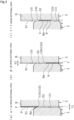
- a mechanical seal 1 for general industrial machines shown in FIG. 1 is an inside mechanical seal that seals a sealed liquid L tending to leak from the radially outer side of sliding surfaces toward the radially inner side, and mainly includes a stationary seal ring 5 as an annular seal ring that is a sliding component provided in a housing 4 of an attached device so as not to be rotatable but be movable in an axial direction, and a rotating seal ring 3 as an annular seal ring that is a sliding component provided on a side of a rotating shaft 8, which drives a pump impeller (not shown) on a high-pressure fluid side, via a sleeve 2 so as to be integrally rotatable with the rotating shaft 8.
- a stationary seal ring 5 as an annular seal ring that is a sliding component provided in a housing 4 of an attached device so as not to be rotatable but be movable in an axial direction
- a rotating seal ring 3 as an annular seal ring that is a sliding component provided on
- the stationary seal ring 5 and the rotating seal ring 3 are configured such that a sliding surface S1 of the stationary seal ring 5 and a sliding surface S2 of the rotating seal ring 3 are brought into close contact with each other and slid against each other by a spring 6 which biases the stationary seal ring 5 in the axial direction and a bellows 7.
- the sliding surface S2 of the rotating seal ring 3 is a flat surface, and recessed portions such as grooves are not provided in the flat surface.
- a base member B is made of hard ceramics (e.g., silicon nitride, zirconia, alumina, SiC, or the like), and a diamond like carbon (abbreviated to DLC) film F is formed on a facing surface Ba facing the rotating seal ring 3 that is flat.
- DLC diamond like carbon
- waveform shapes having substantially the same width are formed in an annular shape in the DLC film F, and a land 9 of the sliding surface S1 is formed in a circumferential direction.
- the film is not limited to the DLC film, and a titanium nitride (abbreviated to TiN) film may be formed.
- a DLC film may be formed all over the sliding surface S2 of the rotating seal ring 3.
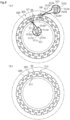
- a plurality of inward recessed portions 11 and a plurality of outward recessed portions 12 are arranged at equal intervals in the circumferential direction at locations other than the land 9 of the sliding surface S1 of the stationary seal ring 5.
- the sliding surface S1 is formed of the land 9, the inward recessed portions 11, and the outward recessed portions 12.
- the land 9 is a contact region of the sliding surface S1
- the inward recessed portions 11 and the outward recessed portions 12 are non-contact regions of the sliding surface S1.
- the inward recessed portion 11 is recessed from an upper surface of the land 9 in the axial direction, has a shape that is surrounded by a quadratic curve or hyperbolic curve in a view seen in the axial direction with respect to a radial line D1 indicated by an alternate long and short dash line extending in a radial direction of the sliding surface S1, and is partitioned off by an opening portion 11a which is open to the radially inner side of the stationary seal ring 5, a peripheral wall 11b as a radially inner side peripheral edge of the land 9, and a bottom wall 11c formed of an upper surface of the base member B (refer to FIG.
- a dimension X1 in the circumferential direction of a radially inner side boundary of a region facing the sliding surface S2 of the rotating seal ring 3 is longer than a dimension Y1 in the axial direction from the upper surface of the land 9 to the bottom wall 11c (refer to FIG. 3A ) (i.e., X1 > Y1).
- the outward recessed portion 12 is recessed from the upper surface of the land 9 in the axial direction, has a shape that is surrounded by a quadratic curve or hyperbolic curve in a view seen in the axial direction with respect to a radial line D2 indicated by an alternate long and short dash line extending in the radial direction of the sliding surface S1, and is partitioned off by an opening portion 12a which is open to the radially outer side of the stationary seal ring 5, a peripheral wall 12b as a radially outer side peripheral edge of the land 9, and a bottom wall 12c formed of the upper surface of the base member B (refer to FIG.
- a dimension X2 in the circumferential direction of a radially outer side boundary of the region facing the sliding surface S2 of the rotating seal ring 3 is longer than a dimension Y2 in the axial direction from the upper surface of the land 9 to the bottom wall 12c (refer to FIG. 3B ) (i.e., X2 > Y2).
- the closed end 12d of the outward recessed portion 12 is located closer to the radially inner side than the closed end 11d of the inward recessed portion 11, namely, the inward recessed portion 11 and the outward recessed portion 12 overlap each other in the circumferential direction.
- the width of the sliding surface S1 of the stationary seal ring 5 is wider than the width of the sliding surface S2 of the rotating seal ring 3 (refer to FIG. 3A ) in the radial direction. For this reason, when the rotating seal ring 3 is subjected to relative rotation, even if the rotating seal ring 3 is temporarily shifted in the radial direction, the rotating seal ring 3 can slide against the stationary seal ring 5 in a state where the land 9, the inward recessed portions 11, and the outward recessed portions 12 of the sliding surface S1 of the stationary seal ring 5 are located on the entire surface of the sliding surface S2 of the rotating seal ring 3.
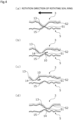
- the sliding surfaces S1 and S2 have a microscopically uneven shape, and as shown in FIG. 4A , when the rotating seal ring 3 rotates with respect to the stationary seal ring 5 in the direction of an arrow, a protruding portion 15 of the land 9 of the sliding surface S1 and a protruding portion 13 of the sliding surface S2 come into contact with each other.
- the sliding surfaces S1 and S2 form respective surface layers that are physically and chemically stable in a microscopic point of view (namely, inactivated), and the surface layers are shown by hatching in FIG. 4 .
- a part of one (here, assumed to be a rotating seal ring 3 side) protruding portion 13 may be chipped off to generate the fine wear debris 10.
- an inactivated external surface is removed at a chipped location 14 of the protruding portion 13, so that a deep portion of the rotating seal ring 3 is exposed and enters a state where the deep portion is likely to bond with another material (namely, an activated state).
- the rotating seal ring 3 is made of SiC
- the protruding portion 13 of the external surface of the sliding surface S2 is chipped off, so that an end surface of the chipped location has a so-called bonding hand such as Si-.
- the chipped location 14 where a part of the protruding portion 13 is chipped off and an activate layer is exposed is slid for a while in the state where the chipped location 14 is exposed to the sealed liquid L, so that due to thermal, mechanical, and chemical actions, the chipped location has substantially the same structure as that of a surface layer therearound and is inactivated. For this reason, even if the wear debris 10 floats on the land 9, since the chipped location 14 is inactivated over the elapse of time, the wear debris 10 is unlikely to adhere to the chipped location 14. Incidentally, the same applies to when wear debris is generated from the DLC film F of the land 9 of the sliding surface S1.
- the wear debris 10 chipped off from the land 9 is likely to be reliably collected in the inward recessed portion 11 or the outward recessed portion 12 as the rotating seal ring 3 and the stationary seal ring 5 rotate relative to each other.
- the wear debris 10 chipped off from the land 9 is likely to be reliably collected in the inward recessed portion 11 or the outward recessed portion 12 as the rotating seal ring 3 and the stationary seal ring 5 rotate relative to each other.
- the wear debris 10 can be reliably collected in any rotation direction.
- the wear debris 10 collected in the inward recessed portion 11 is more likely to be discharged to the radially inner side than to the sliding surface S1
- the wear debris 10 collected in the outward recessed portion 12 is more likely to be discharged to the radially outer side than to the sliding surface S1.
- the wear debris 10 collected in the inward recessed portion 11 or the outward recessed portion 12 is likely to be smoothly discharged to the radially inner side or the radially outer side of the sliding surface S1.
- the wear debris 10 collected in the inward recessed portion 11 or the outward recessed portion 12 is likely to be discharged to the radially inner side or the radially outer side of the sliding surface S1.
- the land 9 is formed of a DLC film F or a TiN film, the height of the land 9 can be made extremely low, and the coefficient of friction generated between the rotating seal ring 3 and the stationary seal ring 5 is likely to be reduced.
- the inward recessed portions 11 and the outward recessed portions 12 of the sliding surface S1 are formed shallow, intrusion of foreign material from outside can be suppressed.
- a mechanical seal according to a second embodiment of the present invention will be described with reference to FIG. 6 . Incidentally, description of the same and duplicated configurations as the configurations of the first embodiment will be omitted.
- a plurality of inward recessed portions 111 and a plurality of outward recessed portions 112 are arranged at equal intervals in a circumferential direction at locations other than a land 109 of a sliding surface S3 of a stationary seal ring 105.
- the inward recessed portions 111 has a shape that is surrounded by a substantially semicircle in a view seen in an axial direction with respect to a radial line D3 indicated by an alternate long and short dash line extending in a radial direction of the sliding surface S3, and is partitioned off by an opening portion 111a which is open to a radially inner side of the stationary seal ring 105, a peripheral wall 111b which has an arc shape and forms a radially inner side peripheral edge of the land 109, and a bottom wall 111c formed of the upper surface of the base member B, which is substantially perpendicular to the peripheral wall 111b, extends to the radially inner side, and is parallel to an upper surface of the land 109.
- a radially outermost side of the inward recessed portions 111 is referred to as a closed end 111d.
- the outward recessed portions 112 has a shape that is surrounded by a semicircle in a view seen in the axial direction with respect to a radial line D4 indicated by an alternate long and short dash line extending in the radial direction of the sliding surface S3, and is partitioned off by an opening portion 112a which is open to a radially outer side of the stationary seal ring 105, a peripheral wall 112b forming a radially outer side peripheral edge of the land 109, and a bottom wall 112c formed of the upper surface of the base member B, which is substantially perpendicular to the peripheral wall 112b, extends to the radially outer side, and is parallel to the upper surface of the land 109.
- a radially innermost side of the outward recessed portions 112 is referred to as a closed end 112d.
- the wear debris 10 generated by wear of the sliding surfaces S3 and S2 is caused to flow in a rotation direction and move from the land 109 of the sliding surface S3 to the inward recessed portions 111 or the outward recessed portions 112 by the sealed liquid L along with the rotation of the rotating seal ring 3, the wear debris 10 is discharged, together with the flow of the sealed liquid L, to the outside of the rotating seal ring 3.
- the closed end 111d of the inward recessed portions 111 and the closed end 112d of the outward recessed portions 112 are arranged on respective substantially concentric circles. For this reason, the closed end 111d of the inward recessed portions 111 and the closed end 112d of the outward recessed portions 112 are aligned with each other in the circumferential direction. Therefore, the wear debris 10 chipped off from the land 109 is likely to be reliably collected in the inward recessed portions 111 or the outward recessed portions 112 as the rotating seal ring 3 and the stationary seal ring 105 rotate relative to each other.
- a mechanical seal according to a third embodiment of the present invention will be described with reference to FIG. 7 . Incidentally, description of the same and duplicated configurations as the configurations of the first embodiment will be omitted.
- a plurality of inward recessed portions 211 and a plurality of outward recessed portions 212 are arranged at equal intervals in a circumferential direction at locations other than a land 209 of a sliding surface S4 of a stationary seal ring 205.
- the inward recessed portion 211 has a shape that is surrounded by a substantially rectangular shape in a view seen in an axial direction with respect to a radial line D5 indicated by an alternate long and short dash line extending in a radial direction of the sliding surface S4, and is partitioned off by an opening portion 211a which is open to a radially inner side of the stationary seal ring 205, peripheral walls 211b, 211b', and 211b'' forming a radially inner side peripheral edge of the land 209, and a bottom wall 211c formed of the upper surface of the base member B, which is substantially perpendicular to the peripheral walls 211b, 211b', and 211b", extends to the radially inner side, and is parallel to an upper surface of the land 209.
- a radially outermost side of the inward recessed portion 211 is referred to as a closed end 211d.
- the outward recessed portion 212 has a shape that is surrounded by a rectangular shape in a view seen in an axial direction with respect to a radial line D6 indicated by an alternate long and short dash line extending in the radial direction of the sliding surface S4, and is partitioned off by an opening portion 212a which is open to a radially outer side of the stationary seal ring 205, peripheral walls 212b, 212b', and 212b'' forming a radially outer side peripheral edge of the land 209, and a bottom wall 212c formed of the upper surface of the base member B, which is substantially perpendicular to the peripheral walls 212b, 212b', and 212b", extends to the radially outer side, and is parallel to the upper surface of the land 209.
- a radially innermost side of the outward recessed portions 212 is referred to as a closed end 212d.
- the wear debris 10 generated by wear of the sliding surfaces S4 and S2 is caused to flow in a rotation direction and move from the land 209 of the sliding surface S4 to the inward recessed portions 211 or the outward recessed portions 212 by the sealed liquid L along with the rotation of the rotating seal ring 3, the wear debris 10 is discharged, together with the flow of the sealed liquid L, to the outside of the rotating seal ring 3.
- the closed end 211d of the inward recessed portions 211 and the closed end 212d of the outward recessed portions 212 are arranged on respective substantially concentric circles. For this reason, the closed end 211d of the inward recessed portions 211 and the closed end 212d of the outward recessed portions 212 are aligned with each other in the circumferential direction. Therefore, the wear debris 10 chipped off from the land 209 is likely to be reliably collected in the inward recessed portions 211 or the outward recessed portions 212 as the rotating seal ring 3 and the stationary seal ring 205 rotate relative to each other.
- a mechanical seal according to a fourth embodiment of the present invention will be described with reference to FIG. 8 . Incidentally, description of the same and duplicated configurations as the configurations of the first embodiment will be omitted.
- the width in a radial direction of a sliding surface S5 of a stationary seal ring 305 is substantially the same as the width in the radial direction of the sliding surface S2 of the rotating seal ring 3, and a plurality of inward recessed portions 311 and a plurality of outward recessed portions 312 are arranged at equal intervals in a circumferential direction at locations other than a land 309 of the sliding surface S5.
- the inward recessed portion 311 has a shape that is surrounded by a substantially rectangular shape in a view seen in an axial direction with respect to a radial line D7 indicated by an alternate long and short dash line extending in the radial direction of the sliding surface S5, and is partitioned off by an opening portion 311a which is open to a radially inner side of the stationary seal ring 305, peripheral walls 311b, 311b', and 311b'' forming a radially inner side peripheral edge of the land 309, and a bottom wall 311c formed of the upper surface of the base member B, which is substantially perpendicular to the peripheral walls 311b, 311b', and 311b", extends to the radially inner side, and is parallel to an upper surface of the land 309.
- a radially outermost side of the inward recessed portion 311 is referred to as a closed end 311d.
- the outward recessed portion 312 has a shape that is surrounded by a rectangular shape in a view seen in an axial direction with respect to a radial line D8 indicated by an alternate long and short dash line extending in the radial direction of the sliding surface S5, and is partitioned off by an opening portion 312a which is open to a radially outer side of the stationary seal ring 305, peripheral walls 312b, 312b', and 312b'' forming a radially outer side peripheral edge of the land 309, and a bottom wall 312c formed of the upper surface of the base member B, which is substantially perpendicular to the peripheral walls 312b, 312b', and 312b", extends to the radially outer side, and is parallel to the upper surface of the land 309.
- a radially innermost side of the outward recessed portions 312 is referred to as a closed end 312d.
- the wear debris 10 generated by wear of the sliding surfaces S5 and S2 is caused to flow in a rotation direction and move from the land 309 of the sliding surface S5 to the inward recessed portions 311 or the outward recessed portions 312 by the sealed liquid L along with the rotation of the rotating seal ring 3, the wear debris 10 is discharged, together with the flow of the sealed liquid L, to the outside of the rotating seal ring 3.
- the closed end 311d of the inward recessed portions 311 and the closed end 312d of the outward recessed portions 312 are arranged on respective substantially concentric circles. For this reason, the closed end 311d of the inward recessed portions 311 and the closed end 312d of the outward recessed portions 312 are aligned with each other in the circumferential direction. Therefore, the wear debris 10 chipped off from the land 309 is likely to be reliably collected in the inward recessed portions 311 or the outward recessed portions 312 as the rotating seal ring 3 and the stationary seal ring 305 rotate relative to each other.
- the land is formed by providing the DLC film F on the sliding surface; however, the present invention is not limited thereto, and the land may be formed by forming recessed portions by the cutting of the sliding surface.
- the present invention is not limited thereto, and the land, the inward recessed portions, and the outward recessed portions may not be formed in one of the rotating seal ring and the stationary seal ring, but preferably, may be provided in one of the rotating seal ring and the stationary seal ring.
- the relative positions of the land, the inward recessed portions, and the outward recessed portions are not shifted, not only the structure can be simplified, but also reliable sealing between the radially inner side and the radially outer side can be provided.
- the configurations have been described in which the inward recessed portion 11 and the outward recessed portion 12 overlap each other in the circumferential direction in the first embodiment and in which the closed end of the inward recessed portion and the closed end of the outward recessed portion are aligned with each other in the circumferential direction in the second to fourth embodiments; however, the present invention is not limited thereto, the closed end of the inward recessed portion and the closed end of the outward recessed portion may be aligned with each other in the circumferential direction in the first embodiment, and the closed end of the inward recessed portion and the closed end of the outward recessed portion may overlap each other in the circumferential direction in the second to fourth embodiments. Further, in the first to fourth embodiments, a configuration may be adopted in which the inward recessed portion and the outward recessed portion do not overlap each other and the closed ends are not aligned with each other in the circumferential direction.
- the shapes of the inward recessed portion and the outward recessed portion are not limited to the shapes provided in each embodiment, and may be, for example, a substantially triangular shape in a view seen in the axial direction.
- the numbers of the inward recessed portions and the outward recessed portions are not limited to the numbers shown in FIG. 2 and FIGS. 6 to 8 , and may be any number.
- the configuration has been described in which the plurality of inward recessed portions and the plurality of outward recessed portions are arranged at equal intervals in the circumferential direction; however, the present invention is not limited thereto, and the plurality of inward recessed portions and the plurality of outward recessed portions may not be arranged at equal intervals in the circumferential direction.
- the configuration has been described in which the plurality of inward recessed portions and the plurality of outward recessed portions are alternately arranged in the circumferential direction; however, the present invention is not limited thereto, and for example, the inward recessed portion, the inward recessed portion, the outward recessed portion, the outward recessed portion, etc. may be arranged in order in the circumferential direction.
- the land may be provided with grooves for generating positive pressure or negative pressure, or dimples for improving lubricity.
- Particular embodiments of the present invention may comprise the sets of features listed in the following numbered statements 1 to 8.
- a sliding component comprising a pair of seal rings which are arranged to rotate relative to each other
- each of the inward recessed portions and each of the outward recessed portions have a line-symmetrical shape with respect to radial lines, respectively.
- each of the inward recessed portions is formed to increase in width toward the radially inner side, and each of the outward recessed portions is formed to increase in width toward the radially outer side.
Landscapes
- Engineering & Computer Science (AREA)
- General Engineering & Computer Science (AREA)
- Mechanical Engineering (AREA)
- Chemical & Material Sciences (AREA)
- Oil, Petroleum & Natural Gas (AREA)
- Physics & Mathematics (AREA)
- Fluid Mechanics (AREA)
- Mechanical Sealing (AREA)
- Sliding-Contact Bearings (AREA)
Applications Claiming Priority (3)
| Application Number | Priority Date | Filing Date | Title |
|---|---|---|---|
| JP2019159594 | 2019-09-02 | ||
| EP20859735.1A EP4027028B1 (fr) | 2019-09-02 | 2020-08-25 | Composant de glissement |
| PCT/JP2020/032010 WO2021044904A1 (fr) | 2019-09-02 | 2020-08-25 | Composant de glissement |
Related Parent Applications (2)
| Application Number | Title | Priority Date | Filing Date |
|---|---|---|---|
| EP20859735.1A Division-Into EP4027028B1 (fr) | 2019-09-02 | 2020-08-25 | Composant de glissement |
| EP20859735.1A Division EP4027028B1 (fr) | 2019-09-02 | 2020-08-25 | Composant de glissement |
Publications (1)
| Publication Number | Publication Date |
|---|---|
| EP4400733A1 true EP4400733A1 (fr) | 2024-07-17 |
Family
ID=74853226
Family Applications (2)
| Application Number | Title | Priority Date | Filing Date |
|---|---|---|---|
| EP24156603.3A Pending EP4400733A1 (fr) | 2019-09-02 | 2020-08-25 | Composant coulissant |
| EP20859735.1A Active EP4027028B1 (fr) | 2019-09-02 | 2020-08-25 | Composant de glissement |
Family Applications After (1)
| Application Number | Title | Priority Date | Filing Date |
|---|---|---|---|
| EP20859735.1A Active EP4027028B1 (fr) | 2019-09-02 | 2020-08-25 | Composant de glissement |
Country Status (5)
| Country | Link |
|---|---|
| US (1) | US12234914B2 (fr) |
| EP (2) | EP4400733A1 (fr) |
| JP (1) | JP7391487B2 (fr) |
| CN (3) | CN120720406A (fr) |
| WO (1) | WO2021044904A1 (fr) |
Families Citing this family (2)
| Publication number | Priority date | Publication date | Assignee | Title |
|---|---|---|---|---|
| JP7846066B2 (ja) * | 2023-09-05 | 2026-04-14 | イーグル工業株式会社 | 摺動部品 |
| WO2026004744A1 (fr) * | 2024-06-28 | 2026-01-02 | イーグル工業株式会社 | Paire de composants coulissants |
Citations (7)
| Publication number | Priority date | Publication date | Assignee | Title |
|---|---|---|---|---|
| GB2197396A (en) * | 1986-10-28 | 1988-05-18 | Pacific Wietz Gmbh & Co Kg | Gas sealing device for shaft |
| SU1707372A1 (ru) * | 1989-11-20 | 1992-01-23 | Б.С.Захаров | Аксиальное уплотнение |
| EP2940353A1 (fr) * | 2012-12-25 | 2015-11-04 | Eagle Industry Co., Ltd. | Élément coulissant |
| CN106763792A (zh) * | 2016-12-28 | 2017-05-31 | 合肥通用机械研究院 | 一种适用于干摩擦工况的自冷却机械密封装置 |
| JP2017207209A (ja) | 2013-09-18 | 2017-11-24 | イーグル工業株式会社 | しゅう動部品 |
| EP4080090A1 (fr) * | 2019-12-17 | 2022-10-26 | Eagle Industry Co., Ltd. | Composant coulissant |
| EP4177485A1 (fr) * | 2020-07-06 | 2023-05-10 | Eagle Industry Co., Ltd. | Élément coulissant |
Family Cites Families (22)
| Publication number | Priority date | Publication date | Assignee | Title |
|---|---|---|---|---|
| NL7213192A (fr) * | 1972-09-29 | 1974-04-02 | ||
| US3855624A (en) * | 1973-08-15 | 1974-12-17 | Philips Corp | Grooved air bearing head |
| JPS6199717A (ja) * | 1984-10-19 | 1986-05-17 | Ebara Corp | 軸受装置 |
| US5368314A (en) * | 1986-10-28 | 1994-11-29 | Pacific Wietz Gmbh & Co. Kg | Contactless pressurizing-gas shaft seal |
| US5066026A (en) * | 1990-06-11 | 1991-11-19 | Kaydon Corporation | Gas face seal |
| GB9103217D0 (en) * | 1991-02-15 | 1991-04-03 | Crane John Uk Ltd | Mechanical face seals |
| JP2001506927A (ja) * | 1996-08-02 | 2001-05-29 | フロウサーヴ・マネジメント・カンパニー | 波形面リングを形成する方法及び装置 |
| US6213473B1 (en) * | 1999-03-06 | 2001-04-10 | Utex Industries, Inc. | Double gas seal with coplanar pad faces |
| JP2001032904A (ja) * | 1999-07-19 | 2001-02-06 | Koyo Seiko Co Ltd | 一方向クラッチと軸受との組立体 |
| US20040026868A1 (en) * | 2002-08-02 | 2004-02-12 | Dahlheimer John C. | Face seal with secondary seal |
| US7540501B2 (en) * | 2004-11-05 | 2009-06-02 | Flowserve Management Company | Segmented shaft seal |
| JP5122607B2 (ja) * | 2010-06-17 | 2013-01-16 | キヤノンマシナリー株式会社 | 平面摺動機構 |
| US8672552B2 (en) * | 2011-07-15 | 2014-03-18 | Us Synthetic Corporation | Bearing assemblies |
| JP5727899B2 (ja) * | 2011-08-31 | 2015-06-03 | 大豊工業株式会社 | ワッシャ |
| JP5727910B2 (ja) * | 2011-09-27 | 2015-06-03 | 大豊工業株式会社 | ワッシャ |
| JP5985999B2 (ja) * | 2013-01-18 | 2016-09-06 | イーグル工業株式会社 | 密封装置 |
| JP6415904B2 (ja) * | 2014-09-09 | 2018-10-31 | イーグル工業株式会社 | シール装置及びその装置に用いるパッキン |
| EP3284981B1 (fr) * | 2015-04-15 | 2020-11-04 | Eagle Industry Co., Ltd. | Pièces coulissantes |
| JP6696085B2 (ja) * | 2016-08-12 | 2020-05-20 | イーグル工業株式会社 | リップシール |
| KR102276083B1 (ko) * | 2017-01-30 | 2021-07-13 | 이구루코교 가부시기가이샤 | 슬라이딩 부품 |
| JP6859832B2 (ja) * | 2017-04-27 | 2021-04-14 | 日本電産株式会社 | 流体軸受装置、モータおよびディスク駆動装置 |
| EP3739242A4 (fr) * | 2018-01-12 | 2021-10-13 | Eagle Industry Co., Ltd. | Élément coulissant |
-
2020
- 2020-08-25 EP EP24156603.3A patent/EP4400733A1/fr active Pending
- 2020-08-25 JP JP2021543709A patent/JP7391487B2/ja active Active
- 2020-08-25 CN CN202510902491.7A patent/CN120720406A/zh active Pending
- 2020-08-25 CN CN202080059723.2A patent/CN114270080B/zh active Active
- 2020-08-25 US US17/636,786 patent/US12234914B2/en active Active
- 2020-08-25 CN CN202411362023.7A patent/CN119123068A/zh active Pending
- 2020-08-25 EP EP20859735.1A patent/EP4027028B1/fr active Active
- 2020-08-25 WO PCT/JP2020/032010 patent/WO2021044904A1/fr not_active Ceased
Patent Citations (7)
| Publication number | Priority date | Publication date | Assignee | Title |
|---|---|---|---|---|
| GB2197396A (en) * | 1986-10-28 | 1988-05-18 | Pacific Wietz Gmbh & Co Kg | Gas sealing device for shaft |
| SU1707372A1 (ru) * | 1989-11-20 | 1992-01-23 | Б.С.Захаров | Аксиальное уплотнение |
| EP2940353A1 (fr) * | 2012-12-25 | 2015-11-04 | Eagle Industry Co., Ltd. | Élément coulissant |
| JP2017207209A (ja) | 2013-09-18 | 2017-11-24 | イーグル工業株式会社 | しゅう動部品 |
| CN106763792A (zh) * | 2016-12-28 | 2017-05-31 | 合肥通用机械研究院 | 一种适用于干摩擦工况的自冷却机械密封装置 |
| EP4080090A1 (fr) * | 2019-12-17 | 2022-10-26 | Eagle Industry Co., Ltd. | Composant coulissant |
| EP4177485A1 (fr) * | 2020-07-06 | 2023-05-10 | Eagle Industry Co., Ltd. | Élément coulissant |
Also Published As
| Publication number | Publication date |
|---|---|
| EP4027028B1 (fr) | 2025-07-09 |
| CN114270080A (zh) | 2022-04-01 |
| JP7391487B2 (ja) | 2023-12-05 |
| CN119123068A (zh) | 2024-12-13 |
| EP4027028A1 (fr) | 2022-07-13 |
| US12234914B2 (en) | 2025-02-25 |
| US20220275865A1 (en) | 2022-09-01 |
| EP4027028A4 (fr) | 2023-10-04 |
| CN114270080B (zh) | 2025-08-05 |
| WO2021044904A1 (fr) | 2021-03-11 |
| JPWO2021044904A1 (fr) | 2021-03-11 |
| CN120720406A (zh) | 2025-09-30 |
Similar Documents
| Publication | Publication Date | Title |
|---|---|---|
| EP3926187B1 (fr) | Composants coulissants | |
| EP3514414B1 (fr) | Joint mécanique | |
| CN110770456B (zh) | 滑动部件 | |
| JP6076971B2 (ja) | 摺動部品 | |
| EP3091257B1 (fr) | Élément de coulissement | |
| CN103649608B (zh) | 滑动部件 | |
| EP4027028B1 (fr) | Composant de glissement | |
| JPWO2013176010A1 (ja) | 摺動部品 | |
| JP7353726B2 (ja) | 摺動部品 | |
| US20260043479A1 (en) | Sliding component | |
| US20250003497A1 (en) | Sliding component | |
| CN117642568A (zh) | 滑动部件 | |
| CN117355692A (zh) | 一种滑动部件 | |
| EP4130523A1 (fr) | Composant coulissant | |
| CN113494609A (zh) | 密封圈 |
Legal Events
| Date | Code | Title | Description |
|---|---|---|---|
| PUAI | Public reference made under article 153(3) epc to a published international application that has entered the european phase |
Free format text: ORIGINAL CODE: 0009012 |
|
| STAA | Information on the status of an ep patent application or granted ep patent |
Free format text: STATUS: THE APPLICATION HAS BEEN PUBLISHED |
|
| AC | Divisional application: reference to earlier application |
Ref document number: 4027028 Country of ref document: EP Kind code of ref document: P |
|
| AK | Designated contracting states |
Kind code of ref document: A1 Designated state(s): AL AT BE BG CH CY CZ DE DK EE ES FI FR GB GR HR HU IE IS IT LI LT LU LV MC MK MT NL NO PL PT RO RS SE SI SK SM TR |
|
| STAA | Information on the status of an ep patent application or granted ep patent |
Free format text: STATUS: REQUEST FOR EXAMINATION WAS MADE |
|
| 17P | Request for examination filed |
Effective date: 20250108 |
|
| STAA | Information on the status of an ep patent application or granted ep patent |
Free format text: STATUS: EXAMINATION IS IN PROGRESS |