EP4400912A1 - Laserschreiber und verfahren zum betreiben eines laserschreibers - Google Patents
Laserschreiber und verfahren zum betreiben eines laserschreibers Download PDFInfo
- Publication number
- EP4400912A1 EP4400912A1 EP23150884.7A EP23150884A EP4400912A1 EP 4400912 A1 EP4400912 A1 EP 4400912A1 EP 23150884 A EP23150884 A EP 23150884A EP 4400912 A1 EP4400912 A1 EP 4400912A1
- Authority
- EP
- European Patent Office
- Prior art keywords
- acousto
- modulator
- laser
- beams
- lenses
- Prior art date
- Legal status (The legal status is an assumption and is not a legal conclusion. Google has not performed a legal analysis and makes no representation as to the accuracy of the status listed.)
- Withdrawn
Links
Images



Classifications
-
- G—PHYSICS
- G03—PHOTOGRAPHY; CINEMATOGRAPHY; ANALOGOUS TECHNIQUES USING WAVES OTHER THAN OPTICAL WAVES; ELECTROGRAPHY; HOLOGRAPHY
- G03F—PHOTOMECHANICAL PRODUCTION OF TEXTURED OR PATTERNED SURFACES, e.g. FOR PRINTING, FOR PROCESSING OF SEMICONDUCTOR DEVICES; MATERIALS THEREFOR; ORIGINALS THEREFOR; APPARATUS SPECIALLY ADAPTED THEREFOR
- G03F7/00—Photomechanical, e.g. photolithographic, production of textured or patterned surfaces, e.g. printing surfaces; Materials therefor, e.g. comprising photoresists; Apparatus specially adapted therefor
- G03F7/70—Microphotolithographic exposure; Apparatus therefor
- G03F7/70383—Direct write, i.e. pattern is written directly without the use of a mask by one or multiple beams
- G03F7/704—Scanned exposure beam, e.g. raster-, rotary- and vector scanning
-
- G—PHYSICS
- G03—PHOTOGRAPHY; CINEMATOGRAPHY; ANALOGOUS TECHNIQUES USING WAVES OTHER THAN OPTICAL WAVES; ELECTROGRAPHY; HOLOGRAPHY
- G03F—PHOTOMECHANICAL PRODUCTION OF TEXTURED OR PATTERNED SURFACES, e.g. FOR PRINTING, FOR PROCESSING OF SEMICONDUCTOR DEVICES; MATERIALS THEREFOR; ORIGINALS THEREFOR; APPARATUS SPECIALLY ADAPTED THEREFOR
- G03F7/00—Photomechanical, e.g. photolithographic, production of textured or patterned surfaces, e.g. printing surfaces; Materials therefor, e.g. comprising photoresists; Apparatus specially adapted therefor
- G03F7/70—Microphotolithographic exposure; Apparatus therefor
- G03F7/70008—Production of exposure light, i.e. light sources
- G03F7/70025—Production of exposure light, i.e. light sources by lasers
Definitions
- the present technology relates in general to laser writers, and in particular to scanning lithographic laser writers having movable writing head, and methods for operating such laser writers.
- Scanning lithographic laser writers e.g. mask writers, use laser to generate or write highly detailed patterns.
- Pattern Generators can today generate features down to the size of 0.75 ⁇ m.
- laser writers use a laser as the light source to activate a photoresist.
- the exposure laser works in the visible spectrum at 413.1 nm wavelength, i.e. violet. Power stability and low optical noise of the laser is crucial for writing performance.
- Moving the DOE introduces a set of complications and has some disadvantages.
- Moving the DOE causes for instance a movement of the beams across multiple optical surfaces such as the AOM surfaces, the AOM lens surfaces and the collimation lens surfaces. If these surfaces over which the beams move are not perfect, the beams can pick up aberrations that can show as periodic imperfections in the printed pattern. Movement of the DOE must also be synchronized with the head movement in a very accurate way.
- a general object of the present technology is to improve the optical compensation for a moving writing head.
- an irradiation arrangement for a scanning lithographic laser writer comprises an acousto-optical modulator, a multi-laser-beam source, a first lens array and a writing head.
- the multi-laser-beam source is configured for providing parallel laser beams focused into respective modulator channel positions of the acousto-optical modulator.
- the first lens array comprises first beam lenses having parallel optical axes along a light propagation path.
- the first lens array is a one-dimensional array having a first pitch between the first beam lenses in a direction perpendicular to the light propagation path.
- Focal points of the first beam lenses are coinciding with the respective modulator channel positions of the acousto-optical modulator or with respective modulator channel positions of an image plane of an imaging of the acousto-optical modulator.
- the writing head comprises a second lens array, a collimator lens arrangement, an acousto-optical deflector and a final lens arrangement.
- the collimator lens arrangement is configured to convert light from positions of a collimator object plane to respective beams of angles crossing each other at the acousto-optical deflector.
- the second lens array comprises second beam lenses having parallel optical axes along the light propagation path.
- the second lens array is a one-dimensional array having a second pitch between the second beam lenses in a direction perpendicular to the light propagation path. Focal points of the second beam lenses are positioned at the collimator object plane, whereby the parallel laser beams become focused at the collimator object plane.
- the writing head is movable relative to the acousto-optical modulator along the light propagation path.
- a scanning lithographic laser writer comprises an irradiation arrangement according to the first aspect, a substrate holder and a control unit.
- the substrate holder has attachment means for holding a substrate with a laser-light sensitive surface in a substrate plane.
- the control unit is configured for synchronize movements of the writing head relative to the substrate holder and the acousto-optical modulator to an operation of the acousto-optical modulator.
- a method for operating a scanning lithographic laser writer comprises moving a writing head of an irradiation arrangement relative to an acousto-optical modulator, a multi-laser-beam source, and a first lens array of first beam lenses of the irradiation arrangement and a substrate holder.
- the acousto-optical modulator is operated synchronized to the moving.
- the multi-laser-beam source is configured for providing parallel laser beams focused into respective modulator channel positions of the acousto-optical modulator.
- the first beam lenses have parallel optical axes along a light propagation path.
- the first lens array is a one-dimensional array having a first pitch between the first beam lenses in a direction perpendicular to the light propagation path.
- Focal points of the first beam lenses are coinciding with respective modulator channel positions of the acousto-optical modulator or with respective modulator channel positions of an image plane of an imaging of the acousto-optical modulator.
- the writing head comprises an acousto-optical deflector, a collimator lens arrangement configured to convert light from a number of positions of a collimator object plane to respective beams of a number of angles crossing each other at the acousto-optical deflector and a second lens array of second beam lenses.
- the second beam lenses have parallel optical axes along the light propagation path.
- the second lens array is a one-dimensional array having a second pitch between the second beam lenses in a direction perpendicular to the light propagation path. Focal points of the second beam lenses are positioned at the collimator object plane.
- the writing head is movable relative to the acousto-optical modulator along the light propagation path.
- One advantage with the proposed technology is that it enables having a writer where all beams are fixed in position up to the deflector during an entire printing process. No moving parts are needed to be synchronized, which removes any need of complicated synchronization electronics. Since the beams pass through fixed positions , this will result in having the same quality of exposed spots throughout the entire plate. Other advantages will be appreciated when reading the detailed description.
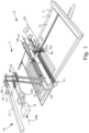
- FIG. 1 For a better understanding of the proposed technology, it may be useful to begin with a brief overview of a model system of a scanning lithographic laser writer 1, as illustrated by Figure 1 .
- This embodiment of a scanning lithographic laser writer 1 is just an example of a system in which the present technology can be applied.
- the present technology may be used in any pattern generator using a multiple-channel acousto-optic modulator.
- a laser beam is generated by a laser source 12.
- a beam splitter 14 in the shape of a Diffractive Optical Element (DOE) 16 splits the laser beam into a number of separate beams 90.
- a set of mirrors and other optical elements direct the separate beams 90 to irradiate a light-sensitive target 7 of a substrate 6 at a substrate holder 5, to create a pattern 9 of exposures in the light-sensitive target 7.
- Each lens, mirror, optical crystal, etc. has some error, giving an energy spread.
- Print data 100 is provided to a control unit 8 for a multichannel acousto-optical modulator 20.
- transducers 24 are used for creating acoustic waves through an acousto-optical crystal 22.
- the separate laser beams 90 can be switched on and off in registry with the moving of the separate laser beams 90 over the light-sensitive target 7, thereby giving rise to the requested pattern.
- the control unit 8 provides modulated radio-frequency signals 102 based on the print data to respective transducers 24 of the multichannel acousto-optical modulator 20 via electrical input connectors.
- the separate laser beams 90 are moved over the light-sensitive target by several mechanisms.
- a Y-interferometer 41 utilizes laser beams from a laser source to determine the position of the separate laser beams 90 in a Y direction.
- An X-interferometer 42 is analogously determining the position in an X direction. Mirrors at a movable writing head 40 are used for this purpose.
- the writing head 40 in an X-carriage is movable along an X-bridge 43 in the direction of the light propagation path 3, as indicated by the arrow 48, and the substrate holder 5 is movable stepwise in the Y-direction relative to the X-bridge 43 as indicate by an arrow.
- the X-carriage thus scans in the X direction (scan strips).
- the Y-stage carrying the substrate holder 5 moves one step length (scan strip width).
- a microsweeping is also available in the Y direction by sweeping the separate laser beams 90 as indicated by the arrow 44, thereby moving the irradiation spots 45 of the separate laser beams 90.
- the microsweeping is in this embodiment achieved by an acousto-optic deflector 60, having an acousto-optical crystal 61.
- a transducer 63 is provided with a sweep signal 65, that is coordinated with the other motions and with the print data 100. The exposure is thus made by writing several microsweeps in one scan strip.
- the AOD deflector crystal 61 generates a sweep for all separate beams 90 together and controls power and linearity over the sweep.
- the printed pattern 9 on the light-sensitive target 7 thus depends on that the separate laser beams 90 are given the right modulation in agreement with the microsweeping and other movement action of the printing head.
- the AOM modulator crystal 22 controls the power for each separate beam 90 and converts pattern data 100 to exposure light.
- the present technology is focused on the light path between the multi-laser-beam source 10 and the writing head 40.
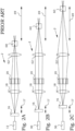
- the figures show three moments during a prior art writing process in which an optical head, of which only the AOD 60 is illustrated, is located at three different positions along the x-bridge. In each position in which the optical head is located it is required that all the beams generated by the DOE 16 should enter the AOD 60 under the exact same angles and to cross at its input. The number of beams is up to 15 in some machines today, and could reach even larger number in future machines. In this way the final lens would receive a constant input and perform in the exact same way as the head moves along the x-bridge. A movement, illustrated by the arrow 69, of the AOD 60 thereby requires that the DOE 16 is moved accordingly, as is illustrated by the arrow 17.
- each lens as an optical element that converts angle to position, the pre-modulator lens arrangement 18 (AOM lenses), or position to angle, the collimator lens arrangement 62.
- AOM lenses AOM lenses
- the beams originating at the DOE 16 all come from the same position in space but under different angles. These angles are converted to separate positions in space inside the AOM 20 by the pre-modulator lens arrangement 18.
- At the output of the AOM 20 there are separate light sources. These separate positions are then converted by the collimator lens arrangement 62 into separate angles which cause the beams to cross at the AOD 69.
- the movement of the DOE 16 causes the beams to move across the surfaces of all the optical elements between the DOE 16 and the optical head. This movement caused each beam to pick up imperfections of the lens surfaces that lead to varying aberrations in the beam shape that change periodically as the head moves up and down along the x-bridge.
- a fixed optical system would therefore be beneficial.
- the distance between adjacent beams only depends on the angle between adject beams introduced by the DOE, which is constant, and not on the distance of the DOE from the pre-modulator lens arrangement 18, also referred to as an AOM lens.
- changing the distance of the DOE 16 from the pre-modulator lens arrangement 18 will not change the positions of the focal spots inside the AOM 20 but only the propagation directions of the beams.
- This distance is exactly equal to the effective focal length (EFL) of the pre-modulator lens arrangement 18. This will be discussed further below.
- a collimator lens arrangement 62 comprising a set of collimation lenses to collimate the beams before entering into the AOD. These lenses guarantee that the beams cross at the AOD location.
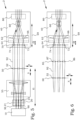
- FIG. 3 A discussion about how the lens-array solution can be used to avoid x-carriage motion compensation will be made in connection with Figure 3 , in which an embodiment of an irradiation arrangement 2 for a scanning lithographic laser writer is illustrated schematically. The illustration is made with 3 beams.
- a multi-laser-beam source 10 is configured for providing parallel laser beams 90 focused into respective modulator channel positions 25 of an acousto-optical modulator (AOM) 20.
- AOM acousto-optical modulator
- the parallel laser beams are provided using a DOE.
- the laser beam incident onto the DOE is collimated, and the number of beams at the output of the DOE are therefore also collimated, but propagate in different directions with an equal angle between adjacent beams.
- the angle depends on the design of the DOE.
- AOM lenses focus these beams in the center of the AOM crystal into focal spots that coincide exactly with the locations of the acoustic waves, i.e. into the respective modulator channel positions 25 of the AOM 20. This means that the distance between adjacent beams is equal to the distance between the modulator channel positions 25.
- the lens arrangements can be used differently compared to prior art. Assume e.g. that the distance between the DOE and the pre-modulator lens arrangement is fixed to the EFL. In this case the multitude of beams 90 propagate parallel to each other but strongly diverge at the output of the AOM 20.
- a multi-laser-beam source 10 is configured for providing parallel laser beams 90 focused into respective modulator channel positions 25 of an AOM 20.
- a first lens array 50 of first beam lenses 52 In this embodiment, a first lens array 50 of first beam lenses 52.
- the first beam lenses 52 are equal with focal length f1 and pitch exactly matching the pitch of the modulator channel positions 25 at the focal distance from the center of the AOM 20.
- the first beam lenses 52 have parallel optical axes along a light propagation path X.
- the first lens array 50 is a one-dimensional array having a first pitch between the first beam lenses 52 in a direction Z perpendicular to the light propagation path X.
- the focal points in a focal plane 21 of the first beam lenses 52 are coinciding with respective modulator channel 25 positions of the AOM.
- Parallel laser beams 92 associated with a respective modulator channel 25 position are provided. In this way all beams 92 will be collimated after the first lens array 50 and will still propagate parallel to each other.
- a movable writing head 40 comprises a collimator lens arrangement 62, an acousto-optical deflector 60 and a final lens arrangement 80.
- the collimator lens arrangement 62 is configured to convert light from positions of a collimator object plane 64 to respective beams of angles crossing each other at the acousto-optical deflector 60. The microsweeping is achieved by the acousto-optic deflector 60.
- the final lens arrangement 80 typically comprising a cylindrical lens, provides an array of parallel beams from of the micro-swept beams exiting from the acousto-optic deflector 60. This array of parallel beams therefore becomes micro-swept in the Y direction on the target, according to procedures, known as such in prior art.
- these beams 92 will reach the movable writing head 40 without changing significantly in size. However in reality, since they are gaussian beams they will slightly diverge. If it is assumed that, despite this divergence, the beam diameter will not exceed the pitch between the first beam lenses 52, as well as the clear aperture of the lenses, even when the optical head 40 is in its furthest position, then it is possible to place another, second lens array 70 on the writing head 40, together with the collimator lens arrangement 62.
- the collimator lens arrangement 62 has the same purpose as in the current systems, i.e. to collimate the beams and to have them cross at the AOD 60 location. As was discussed before, the collimator lens arrangement 62 basically converts position into angle.
- the focal length f2 controls how fast the beams will diverge, and is preferably chosen so that in combination with the collimator lens arrangement 62, the beam size at the AOD 60 is within a specified range for the AOD 60.
- the writing head 40 is thereby movable relative to the AOM 20 in the first direction X over a distance 69. This movement can thus be provided without requiring any synchronized movements of parts of the multi-laser-beam source 10, the AOM 20 or the first lens array 50.
- the collimator lens arrangement 62 Another purpose of the collimator lens arrangement 62 is alpha-scaling, which actually means to achieve tunability of the crossing angle at the AOD 60. This in turn results in tunability of the beam separation on plate to be irradiated.
- the collimation lens is sketched as a single lens but can be made out of two or more lenses. This will make it tuneable so that the focal length can be adjusted, and therefore also the angle between the different beams, to perform the alpha-scaling in the machine.
- alpha-scaling is typically based on two collimator lenses on motorized rails in order to adjust their position and combined focal length to achieve the wanted angular spacing.
- Figure 4 illustrates one preferred embodiment of a multi-laser-beam source 10.
- multi-laser-beam sources 10 configured for providing parallel, preferably Gaussian, laser beams focused into respective modulator channel positions of an acousto-optical modulator are useful together with the technology presented herein.
- the multi-laser-beam source 10 comprises a laser source 12, a beam splitter 16 and a pre-modulator lens arrangement 18.
- the pre-modulator lens arrangement 18 is configured to direct split beams from the beam splitter 16 as the parallel laser beams 90 towards the AOM.
- the pre-modulator lens arrangement 18 is further configured to focus the directed split beams into the respective modulator channel positions of the AOM.
- the incoming beams should have well defined angles of propagation to end up in the AOM channel locations!
- the beams 90 exiting the multi-laser-beam source 10 should propagate parallel to each other, while at the same time being focused into the AOM. This is possible if the distance between the beam-splitter 16 and the first principal plane of the pre-modulator lens arrangement 18 is equal to the front-EFL. Given that, the beam splitter 16 splits the beams with the perfect angular relation required to end up in the AOM channels starting from a single source beam. This is preferably done by a DOE.
- the first lens array 50 may e.g. have 15 first beam lenses 52 with a pitch of 900 ⁇ m and a lens clear aperture of 700 to 800 ⁇ m.
- the pitch is suitable to be matched to typical AOM channel separations, and the first lens array 50 may therefore image the AOM directly.
- the focal points of the first beam lenses 52 are coinciding with respective modulator channel positions of the acousto-optical modulator.
- the first pitch thus becomes equal to a distance between adjacent the modulator channel positions.
- the pitch between the AOM channels 25 is 900um. Therefore, the beam diameters exiting from the first lens array 50 must be smaller than 900um.
- Such gaussian beams 92 will, however, diverge very rapidly since a gaussian beam divergence is inversely proportional to its waist size. For long distance movements 69 of the writing head 40, which may be even a meter or two, this may be a limiting factor.
- a telescope arrangement 55 may be used between the AOM 20 and the first lens array 50.
- the telescope arrangement 55 has the purpose of magnifying the AOM pitch and to allow the use of larger first beam lenses 52 in the first lens array 50.
- the use of larger beam lenses 52 will allow longer propagation distances 69 for the writing head 40 without having the gaussian beams 92 to exceed the size of the second beam lenses 72. This thereby makes the long-stroke systems more robust.
- the focal length f1 is such that the focal points of the first beam lenses 52 are coinciding with respective modulator channel positions of an image plane 56 of an imaging of the AOM 20.
- the irradiation arrangement 2 comprises a telescope arrangement 55 positioned between the AOM 20 and the first lens array 50.
- the telescope arrangement 55 has an object plane at the modulator channel positions 25 of the AOM 20.
- the focal points of the first beam lenses 52 are coinciding with respective modulator channel positions of an image plane 56 of an imaging of the AOM 20.
- the telescope arrangement 55 is illustrated as consisting of two lenses, one concave and one convex. However, this illustration is only schematic and any type of telescope arrangement 55 may be used that is configured to enlarge the pitch of a set of parallel beams, and may also include a turn upside-down of the set of parallel beams.
- additional optical components are used between the first lens array 50 and the second lens array 70.
- the irradiation arrangement 2 therefore an intermediate lens arrangement 85 positioned between the first lens array 50 and the second lens array 70.
- the intermediate lens arrangement 85 is configured to re-collimate the beams.
- the intermediate lens arrangement 85 comprises a third lens array 86 of third beam lenses 87 aligned with respective third beam lenses 52 of the second lens array 50 along the light propagation path X.
- the third lens array 86 with the third beam lenses, equal to the number of beams, is thereby used for re-collimating the beams.
- the third lens array 86 is provided stationary with respect to the second lens array 50 or with respect to the writing head 40.
- the intermediate lens arrangement 85 comprises a collimation set of lenses in a telescope configuration in a telescope module 88, covering all beams 92.
- the telescope module 88 comprises a pair of lenses with sufficiently large aperture to include all beams 92 in a telescope configuration.
- a first lens and second lens are together used to re-collimate the beams.
- the first lens has focal length f3 and will be placed at a distance f3 from the beam crossing 89 and is thus used to have the beams 92 crossed at a distance f3 from the lens.
- the first lens focuses them, creating crossing beam waists at approximately the distance f3.
- the beams 92 are not perfectly collimated and the location of the beam waist may therefore be a bit further out than the crossing point 89.
- a second lens with focal length f4 will be placed at distance about f3+f4 from the first lens and is used to re-create the set of parallel quasi-collimated beams. If needed more than one module can be introduced, depending on the distance to be covered and the waist-size of the beams.
- f3 and f4 can be identical, as is illustrated, if no magnification is required. In this embodiment, the beams will also change their relative positions, upside down as illustrated. Without magnification, the pitches of the first and second lens arrays 20, 50 are equal and aligned.
- the second pitch is equal to the first pitch and in that the second beam lenses are aligned to the first beam lenses along the light propagation path.
- telescope modules 88 can also be used, e.g. as is illustrated in Figure 8 .
- the telescope module 88 does not only re-collimate the beams, but it also magnifies the beam array. As discussed earlier, use of larger beams may reduce the beam divergence.
- the intermediate lens arrangement 85 has a magnification different from unity.
- the scanning lithographic laser writer 1 comprises an irradiation arrangement 2 according to the principles presented here above.
- the scanning lithographic laser writer 1 further comprises a substrate holder 5 having attachment means for holding a substrate 6 with a laser-light sensitive surface 7 in a substrate plane.
- the scanning lithographic laser writer 1 further comprises a control unit 8.
- the control unit 8 is configured for synchronize movements of the writing head 40 relative to the substrate holder 5 and the AOM 20 to an operation of the AOM 20.
- Figure 9 illustrates a flow diagram of steps of an embodiment of a method for operating a scanning lithographic laser writer.
- a writing head of an irradiation arrangement is moved relative to an AOM, a multi-laser-beam source, and a first lens array of first beam lenses of the irradiation arrangement and a substrate holder.
- the AOM is operated synchronized to the moving.
- the multi-laser-beam source is configured for providing parallel laser beams focused into respective modulator channel positions of the AOM.
- the first beam lenses have parallel optical axes along a light propagation path.
- the first lens array is a one-dimensional array having a first pitch between the first beam lenses in a direction perpendicular to the light propagation path.
- Focal points of the first beam lenses are coinciding with respective modulator channel positions of the AOM or with respective modulator channel positions of an image plane of an imaging of the AOM.
- the writing head comprises an AOD, a collimator lens arrangement configured to convert light from a number of positions of a collimator object plane to respective beams of a number of angles crossing each other at the AOD and a second lens array of second beam lenses.
- the second beam lenses have parallel optical axes along the light propagation path.
- the second lens array is a one-dimensional array having a second pitch between the second beam lenses in a direction perpendicular to the light propagation path.
- Focal points of the second beam lenses are positioned at the collimator object plane.
- the writing head being movable relative to the AOM along the light propagation path.
- This technology provides a way to have a static beam path, i.e., with no moving parts between the laser output and the writing head, while the writing head is moved along the x-bridge.
Landscapes
- Physics & Mathematics (AREA)
- General Physics & Mathematics (AREA)
- Engineering & Computer Science (AREA)
- Optics & Photonics (AREA)
- Plasma & Fusion (AREA)
- Mechanical Optical Scanning Systems (AREA)
Priority Applications (4)
| Application Number | Priority Date | Filing Date | Title |
|---|---|---|---|
| EP23150884.7A EP4400912A1 (de) | 2023-01-10 | 2023-01-10 | Laserschreiber und verfahren zum betreiben eines laserschreibers |
| PCT/EP2024/050335 WO2024149725A1 (en) | 2023-01-10 | 2024-01-09 | Laser writer and method for operating a laser writer |
| KR1020257026194A KR20250141719A (ko) | 2023-01-10 | 2024-01-09 | 레이저 라이터 및 레이저 라이터 동작 방법 |
| CN202480006586.4A CN120418731A (zh) | 2023-01-10 | 2024-01-09 | 激光写入器及操作激光写入器的方法 |
Applications Claiming Priority (1)
| Application Number | Priority Date | Filing Date | Title |
|---|---|---|---|
| EP23150884.7A EP4400912A1 (de) | 2023-01-10 | 2023-01-10 | Laserschreiber und verfahren zum betreiben eines laserschreibers |
Publications (1)
| Publication Number | Publication Date |
|---|---|
| EP4400912A1 true EP4400912A1 (de) | 2024-07-17 |
Family
ID=84901620
Family Applications (1)
| Application Number | Title | Priority Date | Filing Date |
|---|---|---|---|
| EP23150884.7A Withdrawn EP4400912A1 (de) | 2023-01-10 | 2023-01-10 | Laserschreiber und verfahren zum betreiben eines laserschreibers |
Country Status (4)
| Country | Link |
|---|---|
| EP (1) | EP4400912A1 (de) |
| KR (1) | KR20250141719A (de) |
| CN (1) | CN120418731A (de) |
| WO (1) | WO2024149725A1 (de) |
Citations (6)
| Publication number | Priority date | Publication date | Assignee | Title |
|---|---|---|---|---|
| US6307799B1 (en) * | 1998-12-03 | 2001-10-23 | Nanyang Technological University | Acousto optic data storage system on a stationary and high density data storage media |
| US20040109164A1 (en) * | 1999-09-09 | 2004-06-10 | Olympus Optical Co., Ltd. | Rapid depth scanning optical imaging device |
| US20080032066A1 (en) * | 2005-10-26 | 2008-02-07 | Lars Stiblert | Platforms, apparatuses, systems and methods for processing and analyzing substrates |
| EP2659305B1 (de) * | 2010-11-04 | 2017-01-04 | Micronic Mydata AB | Verfahren und vorrichtung zum abtasten einer zweidimensionalen bürste mit einem akustooptischen deflektor (aod) mit erweitertem feld in eine abtastrichtung |
| US20170017163A1 (en) * | 2014-03-11 | 2017-01-19 | V Technology Co., Ltd. | Beam exposure device |
| EP1714193B1 (de) * | 2004-02-13 | 2018-08-01 | Mycronic AB | Bildverbesserung für mehrfachbelichtungsstrahlen |
-
2023
- 2023-01-10 EP EP23150884.7A patent/EP4400912A1/de not_active Withdrawn
-
2024
- 2024-01-09 KR KR1020257026194A patent/KR20250141719A/ko active Pending
- 2024-01-09 CN CN202480006586.4A patent/CN120418731A/zh active Pending
- 2024-01-09 WO PCT/EP2024/050335 patent/WO2024149725A1/en not_active Ceased
Patent Citations (6)
| Publication number | Priority date | Publication date | Assignee | Title |
|---|---|---|---|---|
| US6307799B1 (en) * | 1998-12-03 | 2001-10-23 | Nanyang Technological University | Acousto optic data storage system on a stationary and high density data storage media |
| US20040109164A1 (en) * | 1999-09-09 | 2004-06-10 | Olympus Optical Co., Ltd. | Rapid depth scanning optical imaging device |
| EP1714193B1 (de) * | 2004-02-13 | 2018-08-01 | Mycronic AB | Bildverbesserung für mehrfachbelichtungsstrahlen |
| US20080032066A1 (en) * | 2005-10-26 | 2008-02-07 | Lars Stiblert | Platforms, apparatuses, systems and methods for processing and analyzing substrates |
| EP2659305B1 (de) * | 2010-11-04 | 2017-01-04 | Micronic Mydata AB | Verfahren und vorrichtung zum abtasten einer zweidimensionalen bürste mit einem akustooptischen deflektor (aod) mit erweitertem feld in eine abtastrichtung |
| US20170017163A1 (en) * | 2014-03-11 | 2017-01-19 | V Technology Co., Ltd. | Beam exposure device |
Also Published As
| Publication number | Publication date |
|---|---|
| WO2024149725A1 (en) | 2024-07-18 |
| KR20250141719A (ko) | 2025-09-29 |
| CN120418731A (zh) | 2025-08-01 |
Similar Documents
| Publication | Publication Date | Title |
|---|---|---|
| US7046266B1 (en) | Scanner system | |
| KR100278824B1 (ko) | 개선된 레이저 패턴 발생장치 및 방법 | |
| US5309178A (en) | Laser marking apparatus including an acoustic modulator | |
| JP2006113185A (ja) | レーザ加工装置 | |
| KR20210054561A (ko) | 적응형 레이저빔 형성 방법 및 장치 | |
| JP2011043831A (ja) | 小型結像ヘッド、高速マルチヘッドレーザ結像アセンブリ、および高速マルチヘッドレーザ結像方法 | |
| US20220163894A1 (en) | System and method for double-sided digital lithography or exposure | |
| KR940008359B1 (ko) | 레이저를 이용한 패턴형성장치 | |
| KR20080014992A (ko) | 노광 장치 | |
| KR20040053776A (ko) | 식별코드의 레이저 마킹 방법 및 장치 | |
| US6421180B1 (en) | Apparatus for generating a laser pattern on a photomask and associated methods | |
| JP2006208432A (ja) | 露光方法および装置 | |
| WO2024149725A1 (en) | Laser writer and method for operating a laser writer | |
| CA2694870A1 (en) | Apparatus and method for writing a flip image structure | |
| JPH0687097B2 (ja) | 受動的な反射面追跡型レーザ・ラスタ・スキャナ | |
| CN118605089A (zh) | 一种基于二维振镜的dmd无掩模光刻系统及拼接光刻方法 | |
| US5745150A (en) | Laser drawing apparatus having drawing beams in a common place aligned with a lens meridian | |
| GB2068597A (en) | Laser spatial stabilization transmission system | |
| KR102921824B1 (ko) | 패턴 노광 장치 및 패턴 노광 방법 | |
| WO2007040066A1 (ja) | 描画方法および装置 | |
| EP1524546A1 (de) | Scannersystem mit vor Ort auswechselbarem Lasermodul | |
| JPH05131676A (ja) | 画像走査記録装置 | |
| JP2583919B2 (ja) | 光走査装置 | |
| JPS63155020A (ja) | 画像走査記録装置のレ−ザ露光方法 | |
| JP2000118192A (ja) | 走査式描画装置 |
Legal Events
| Date | Code | Title | Description |
|---|---|---|---|
| PUAI | Public reference made under article 153(3) epc to a published international application that has entered the european phase |
Free format text: ORIGINAL CODE: 0009012 |
|
| STAA | Information on the status of an ep patent application or granted ep patent |
Free format text: STATUS: THE APPLICATION HAS BEEN PUBLISHED |
|
| AK | Designated contracting states |
Kind code of ref document: A1 Designated state(s): AL AT BE BG CH CY CZ DE DK EE ES FI FR GB GR HR HU IE IS IT LI LT LU LV MC ME MK MT NL NO PL PT RO RS SE SI SK SM TR |
|
| STAA | Information on the status of an ep patent application or granted ep patent |
Free format text: STATUS: THE APPLICATION IS DEEMED TO BE WITHDRAWN |
|
| 18D | Application deemed to be withdrawn |
Effective date: 20250118 |