EP4400922A1 - Appareil de terrain avec module radio et procédé de transmission de données à distance - Google Patents
Appareil de terrain avec module radio et procédé de transmission de données à distance Download PDFInfo
- Publication number
- EP4400922A1 EP4400922A1 EP23151077.7A EP23151077A EP4400922A1 EP 4400922 A1 EP4400922 A1 EP 4400922A1 EP 23151077 A EP23151077 A EP 23151077A EP 4400922 A1 EP4400922 A1 EP 4400922A1
- Authority
- EP
- European Patent Office
- Prior art keywords
- housing
- field device
- section
- coupling
- data transmission
- Prior art date
- Legal status (The legal status is an assumption and is not a legal conclusion. Google has not performed a legal analysis and makes no representation as to the accuracy of the status listed.)
- Granted
Links
Images


Classifications
-
- H—ELECTRICITY
- H04—ELECTRIC COMMUNICATION TECHNIQUE
- H04Q—SELECTING
- H04Q9/00—Arrangements in telecontrol or telemetry systems for selectively calling a substation from a main station, in which substation desired apparatus is selected for applying a control signal thereto or for obtaining measured values therefrom
-
- H—ELECTRICITY
- H05—ELECTRIC TECHNIQUES NOT OTHERWISE PROVIDED FOR
- H05K—PRINTED CIRCUITS; CASINGS OR CONSTRUCTIONAL DETAILS OF ELECTRIC APPARATUS; MANUFACTURE OF ASSEMBLAGES OF ELECTRICAL COMPONENTS
- H05K5/00—Casings, cabinets or drawers for electric apparatus
- H05K5/02—Details
- H05K5/0217—Mechanical details of casings
-
- G—PHYSICS
- G08—SIGNALLING
- G08C—TRANSMISSION SYSTEMS FOR MEASURED VALUES, CONTROL OR SIMILAR SIGNALS
- G08C17/00—Arrangements for transmitting signals characterised by the use of a wireless electrical link
- G08C17/02—Arrangements for transmitting signals characterised by the use of a wireless electrical link using a radio link
-
- G—PHYSICS
- G05—CONTROLLING; REGULATING
- G05B—CONTROL OR REGULATING SYSTEMS IN GENERAL; FUNCTIONAL ELEMENTS OF SUCH SYSTEMS; MONITORING OR TESTING ARRANGEMENTS FOR SUCH SYSTEMS OR ELEMENTS
- G05B19/00—Program-control systems
- G05B19/02—Program-control systems electric
- G05B19/04—Program control other than numerical control, i.e. in sequence controllers or logic controllers
- G05B19/042—Program control other than numerical control, i.e. in sequence controllers or logic controllers using digital processors
-
- H—ELECTRICITY
- H02—GENERATION; CONVERSION OR DISTRIBUTION OF ELECTRIC POWER
- H02G—INSTALLATION OF ELECTRIC CABLES OR LINES, OR OF COMBINED OPTICAL AND ELECTRIC CABLES OR LINES
- H02G3/00—Installations of electric cables or lines or protective tubing therefor in or on buildings, equivalent structures or vehicles
- H02G3/22—Installations of cables or lines through walls, floors or ceilings, e.g. into buildings
-
- H—ELECTRICITY
- H04—ELECTRIC COMMUNICATION TECHNIQUE
- H04L—TRANSMISSION OF DIGITAL INFORMATION, e.g. TELEGRAPHIC COMMUNICATION
- H04L12/00—Data switching networks
- H04L12/02—Details
- H04L12/12—Arrangements for remote connection or disconnection of substations or of equipment thereof
-
- H—ELECTRICITY
- H04—ELECTRIC COMMUNICATION TECHNIQUE
- H04Q—SELECTING
- H04Q1/00—Details of selecting apparatus or arrangements
- H04Q1/02—Constructional details
- H04Q1/04—Frames or mounting racks for selector switches; Accessories therefor, e.g. frame cover
-
- H—ELECTRICITY
- H05—ELECTRIC TECHNIQUES NOT OTHERWISE PROVIDED FOR
- H05K—PRINTED CIRCUITS; CASINGS OR CONSTRUCTIONAL DETAILS OF ELECTRIC APPARATUS; MANUFACTURE OF ASSEMBLAGES OF ELECTRICAL COMPONENTS
- H05K9/00—Screening of apparatus or components against electric or magnetic fields
- H05K9/0073—Shielding materials
- H05K9/0081—Electromagnetic shielding materials, e.g. EMI, RFI shielding
Definitions
- the invention relates to a field device with a radio module accommodated in a housing for remote data transmission and to a method for remote data transmission by means of a radio module accommodated in a housing of a field device.
- field devices are often used to record and/or influence process variables. Examples of such field devices are level, limit level, flow, pressure, temperature measuring devices and the like with sensors that record the corresponding process variables level, limit level, flow, pressure, temperature, etc.
- Such field devices are often connected to higher-level units, for example control systems or control units, via remote data transmission. These higher-level units are used for process control, process visualization and/or process monitoring. Remote data transmission can be either wired or wireless.
- Field devices with metal housings are often used due to their mechanical stability and resistance to environmental influences. When field devices are used in potentially explosive environments, they must meet certain requirements that also require the use of metal housings. Openings in the housing are designed in such a way that the explosion cannot be transmitted from the housing. All closures and feedthroughs in the housing must be designed accordingly and are therefore sometimes very complex.
- radio modules can be used to make operation and parameterization of field devices easier. Operation and parameterization via radio modules makes work on site easier for the operating personnel, as the field device does not have to be opened for parameterization, for example, and may not have to be taken out of operation completely.
- the radio modules can also be used for wireless data transmission with a higher-level unit.
- radio modules are incompatible with metal housings. If a radio transmitter/receiver is located together with the rest of the sensor electronics of a field device (e.g. level or pressure sensor) within the field device housing, metal housing walls prevent the propagation of electromagnetic waves and thus the desired radio connection.
- a field device e.g. level or pressure sensor
- the propagation of electromagnetic waves can also be prevented or at least significantly disrupted by a medium that at least partially surrounds the field device, in which the field device is immersed, for example.
- the medium can be water, oil or similar (i.e. flowable), which significantly hinders the propagation of electromagnetic radiation.
- Pourable media such as metal or metal-containing powder, granulate or a combination of pourable and flowable media that partially or completely surround the field device can also significantly restrict or completely prevent a desired radio connection.
- the invention is based on the object of providing a field device with a radio module for remote data transmission and a method for remote data transmission using such a field device, which overcomes the disadvantages known from the prior art.
- the field device and the remote data transmission method should enable reliable data transmission, have a high level of operational reliability, be user-friendly and low-maintenance and, last but not least, be cost-effective to manufacture and implement.
- the term “approximately” used herein is intended to indicate a tolerance range that the person skilled in the art in this field considers to be usual.
- the term “approximately” is to be understood as a tolerance range of the reference size of up to a maximum of +/-20%, preferably up to a maximum of +/-10%.
- a field device for example a level, limit level, flow, pressure, temperature measuring device or similar, has a housing, an electrical connection line led into the housing through a cable duct and a radio module accommodated in the housing for remote data transmission.
- the radio module is arranged and designed in such a way that a remote data transmission signal can be transmitted to and/or received from a section of the connection line located outside the housing by means of a field coupling with a section of the connection line located in the housing.
- the section of the connecting cable located in the housing is also referred to herein as the internal cable section and the section of the connecting cable located outside the housing is also referred to as the external cable section.
- the electrical connection cable can be used, for example, to supply power to the field device, to ground it, or similar.
- the connection cable therefore has at least one electrically conductive wire.
- field coupling can be understood as an electrically contact-free, i.e. non-galvanically connected, coupling of two electronic components via an electric, magnetic or electromagnetic field (i.e. electromagnetic radiation), whereby the field coupling is determined according to the Invention is designed to ensure the transmission of the remote data transmission signal between the radio module and the inner section of the connecting cable.
- the radio module can be designed for unidirectional remote data transmission (ie either only sending or only receiving). Bidirectional remote data transmission (ie both sending and receiving) is also possible.
- the invention enables remote data transmission or data communication with the field device via the internal and external sections of the connecting cable, with a communication partner being located at a distance from the field device. Regardless of the medium that partially or completely surrounds the field device, remote data transmission can be conducted via the connecting cable from the field device housing (and possibly from the medium) to the outside.
- the remote data transmission signal can be tapped from a section of the external connection cable.
- a galvanic (i.e. electrically contact-based) tap can be made in order to detect the electrical signal on the connection cable (i.e. to receive it) or to feed it into it (i.e. to send it).
- the tap can be made electrically contact-free by means of a field coupling between the tap section of the external connection cable and the spatially distant receiver or transmitter, i.e. in the broadest sense by a signal or data transmission using an electrical, magnetic or electromagnetic field (i.e. by means of electromagnetic radiation).
- the field coupling on the external line section can be designed in a similar way to the field coupling between the radio module and the internal line section, but is not necessarily limited to this.
- the external field coupling can also be designed according to a different transmission principle than the internal field coupling.
- the section of the connection cable intended for tapping is preferably not insulated, regardless of whether the tapping or the feeding of the remote data transmission signal on the external connection cable takes place galvanically or by field coupling.
- the external line section can also have several sections at which the remote data transmission signal can be tapped or fed.
- Tapping the remote data transmission signal is understood here to mean both decoupling (i.e. receiving) the signal from the connecting cable and coupling (i.e. sending) a remote data transmission signal from a transmitter on the outside of the housing in order to transmit the remote data transmission signal between the internal cable section and the external cable section.
- decoupling i.e. receiving
- coupling i.e. sending
- a remote data transmission signal from a transmitter on the outside of the housing in order to transmit the remote data transmission signal between the internal cable section and the external cable section.
- bidirectional data transmission can be implemented between the field device-external transmitter/receiver and the radio module or field device.
- the invention enables, among other things, user- and application-friendly operation and parameterization of the field device via the radio module, since the field device does not have to be opened and possibly taken out of operation for this purpose.
- the field device can remain in place during the operation or parameterization process. It is irrelevant whether the field device is already immersed in a medium (e.g. water, oil, granulate, powder, etc.) or surrounded by it or is still without contact with the medium.
- the field device housing can also be made of a metal material without significantly impairing the remote data transmission. This is a particular advantage of the invention. However, field device housings made of a non-metallic material, such as plastic, are by no means excluded and can be used as an alternative or in addition to a metal housing.
- the field device can also transmit measured values to the external receiver/transmitter (e.g. higher-level control center or similar) during normal operation using the remote data transmission disclosed here.
- the invention provides a compact field device in which the radio module can be fully integrated and the remote data transmission signal is transmitted via the connecting cable.
- a field device designed as a level, limit, flow, pressure or temperature measuring device also has a corresponding measuring sensor for detecting a level, limit level, flow, pressure or temperature.
- the field coupling can be designed as a capacitive and/or inductive coupling and/or as an electromagnetic radiation coupling.
- Capacitive coupling refers to the influence of an electric field on the electrical/electronic components involved, e.g. cross-coupling on parallel conductors in a cable or parallel conductor tracks on a circuit board. This effect can be used, for example, between parallel cables with high-ohm termination impedances.
- Inductive coupling refers to the influence of a magnetic field on the electrical/electronic components involved. Inductive coupling is created by magnetic field coupling, usually in conductor loops, e.g. between parallel conductor loops, each of which can have low-ohm termination impedances.
- Radiation coupling refers to the process whereby an electromagnetic field acts on the electrical/electronic components involved in the coupling. Electrical conductors in a cable or on circuit boards can act as an antenna and receive or transmit radio signals. Radiation coupling can occur between cable-cable, field-cable or antenna-antenna and can be used in the sense disclosed here to transmit the remote data transmission signal between the radio module and the internal line section of the connecting line.
- the field coupling between the radio module and the internal cable section of the connecting cable offers the particular advantage that the radio module, including an antenna for wireless data transmission, can be completely arranged and accommodated in the field device housing.
- the field coupling ie capacitive, inductive or through electromagnetic radiation
- the field coupling can thus be achieved without additional Components and without special coupling circuits (e.g. circuit networks with resistors, capacitors, coils and the like).
- the antenna and the internal coupling section of the connecting cable can be designed as parallel conductors or parallel conductor tracks on a circuit board, but are not necessarily limited to this.
- the antenna and the internal cable section intended for coupling can also be designed as conductor loops.
- the radio module has an antenna arranged in the housing, wherein the antenna and the section of the connecting line located inside the housing are designed and arranged for mutual field coupling.
- the radio module is preferably designed, for example, for the use of NFC, RFID, DECT, WiFi/WLAN or Bluetooth radio transmission technologies, without necessarily being limited to these technologies. It is understood that other radio transmission technologies can also be used and the above list is merely exemplary and not to be understood as exhaustive.
- the antenna of the radio module is preferably completely accommodated in the housing.
- the antenna and the inner section of the connecting line can be designed and arranged, for example, as parallel conductors or parallel conductor tracks on a circuit board, whereby other designs and arrangements of the antenna and the inner line section that essentially achieve the same goal are not excluded.
- the radio module e.g. Bluetooth module
- the radio module couples the radio signal or remote data transmission signal into the internal line section of the connecting line (i.e. sends it) or out of it (i.e. receives it).
- the signal can be tapped, for example, at an open, non-insulated end of the connecting line or a section of the connecting line without shielding in the manner disclosed herein.
- the section of the connection cable outside the housing has According to a preferred development, the insulation is transversely and/or longitudinally watertight.
- the insulation can be made of a plastic, for example.
- a longitudinal water seal prevents a liquid medium such as water, oil or similar from penetrating the insulation via free ends or, in the event of damage to the insulation, between two free end sections. The penetration of the liquid medium into other areas of the connecting cable is also prevented with a longitudinal water seal.
- waterproof should not be limited to a sealing effect only against the medium water. Rather, it should be understood as a sealing effect of the insulation against all those media with which the connecting cable can come into contact during the intended use of the field device and which in particular have a detrimental (e.g. dampening) effect on the transmission performance of the remote data transmission signal via the connecting cable.
- These media can be both flowable, such as water, oil or similar, but also pourable, such as granular or powdery media.
- the cable feedthrough can preferably be designed as a fluid-tight connection of the connecting cable to the housing.
- the section of the connecting cable located outside the housing can have at least one insulation-free section for coupling out and/or coupling in the remote data transmission signal.
- the remote data transmission signal can be picked up or received by a receiver external to the field device galvanically, capacitively, inductively or by electromagnetic radiation coupling. an external transmitter. This provides a spatially separate tapping option or, if several insulation-free sections are provided, several tapping options for one or more external transmitters/receivers are available.
- the housing has an electromagnetically effective housing shield.
- the housing shield can, on the one hand, cause a concentration of the field between the radio module (e.g. antenna) and the internal line section of the connecting cable.
- the housing shield can prevent external interference fields from radiating into the housing or at least significantly reduce them.
- the housing shield can be made of an electrically conductive material.
- a plastic housing can have a metallic coating. This can be attached to the outside and/or inside of the housing or embedded in the housing walls.
- the housing may also be partially or completely formed from a metal material that can provide a shielding function alternatively or in addition to a housing coating.
- the housing may have a fully welded metal structure.
- the housing may be completely closed and/or completely metallic, for example in order not to also shield or attenuate the physical quantity to be recorded by a measuring sensor.
- a sensor is generally understood here as a part of the field device which reacts or responds directly to the quantity to be measured.
- a window can be provided in the housing of the field device through which the sensor can detect the physical quantity essentially undisturbed.
- this can be provided on the inside of the housing with a metallic measuring electrode.
- the measuring electrode is used to convert the physical quantity recorded by the sensor into a suitable electrical quantity (e.g. current, voltage).
- the measuring electrode is advantageously used for electromagnetic shielding and/or field concentration.
- the section of the connecting cable located outside the housing can preferably have an electromagnetically effective cable shield. This can be provided over the entire length of the external cable section in order to prevent external interference signals from being coupled directly into the external connecting cable.
- a length of the section of the connecting line located outside the housing can be at least about 2 m, preferably at least about 3 m, even more preferably at least about 5 m.
- the maximum length of the section of the connecting line located outside the housing is preferably at most a few hundred meters, e.g. about 100 to 500 m, preferably at most about 50 to 100 m, even more preferably at most about 15 to 50 m. It has been found that in this way a reliable transmission of the remote data transmission signal can be achieved between the radio module 6 inside the housing and a transmitter/receiver coupled to the external section 10 of the connecting line 5.
- the above length information for the external connecting line indicates in particular the length of the external connecting line used for the remote data transmission of the remote data transmission signal, i.e.
- transmission distances of a few centimeters e.g. 10 cm to 50 cm, up to a few meters, e.g. up to about 10 m to 15 m, can be achieved by means of the remote data transmission according to the invention from the connecting line (i.e. from a tapping section of the connecting line) to a transmitter/receiver.
- the connecting cable is designed as a support cable, on which the housing is held suspended in the operational state of the field device.
- the field device can be designed as a hanging pressure measuring device, which is suspended at the place of use using the connecting cable.
- the design as a support cable is not limited to pressure measuring devices.
- a level or limit level measuring device can be suspended in a container containing a medium to be monitored using the connecting cable designed as a support cable.
- other field measuring devices such as flow, temperature measuring devices, etc. can also be suspended as a support cable using their connecting cable.
- a method for remote data transmission by means of a radio module accommodated in a housing of a field device via an electrical connection line led into the housing through a cable feedthrough is disclosed, wherein a remote data transmission signal is transmitted to and/or received from a section of the connection line located outside the housing by means of a field coupling of the radio module with a section of the connection line located in the housing.
- the field coupling is carried out capacitively and/or inductively and/or by electromagnetic radiation.
- the remote data transmission signal is coupled out and/or coupled in at least a portion of the section of the connecting line located outside the housing by galvanic, capacitive and/or inductive coupling and/or by electromagnetic radiation coupling.
- a further preferred embodiment of the method provides that the housing is held suspended via the connecting cable designed as a support cable in the operational state of the field device.
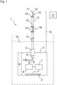
- Fig.1 shows a schematic functional diagram of an embodiment of a field device 1 according to the invention.
- the field device 1 can be designed, without limitation of generality, for example, as a level, limit level, flow, pressure, temperature measuring device or similar, wherein it has a corresponding Measuring sensor 2 for detecting a fill level, limit level, flow, pressure, temperature and the like.
- the sensor 2 is generally understood as a part of the field device 1, which reacts or responds directly to the quantity to be measured.
- the field device 1 has a housing 3, an electrical connection cable 5 led through a cable duct 4 into the housing 3 and a radio module 6 accommodated in the housing 3 for remote data transmission.
- the radio module 6 is in the Fig.1 shown example is connected to an electronic control unit 7.
- the control unit 7 can have a microprocessor, microcontroller, DSP or similar and possibly memory such as RAM, ROM, Flash and the like.
- the control unit 7 is connected to the measuring sensor 2 in order to receive the electronic signals output by the measuring sensor 2 and, if necessary, to process them and, in particular, to transmit them by means of the radio module 6.
- the field device 1 or the control unit 7 can also be designed to receive data via the radio module 6, which can be used, for example, to operate and parameterize the field device 1.
- the radio module 6 in the field device 1 is arranged and designed to transmit and/or receive a remote data transmission signal by means of a field coupling 8 with a section 9 of the connecting line 5 located in the housing 3 into a section 10 of the connecting line 5 located outside the housing 3.
- the connecting cable 5 in the present case has several electrical wires 11, 12, which can be used, for example, to supply power to the field device 1, without, however, necessarily being based on the Fig.1
- the number of cores shown here or to the intended use described here may be more than the number Fig.1
- the number of wires shown or less may be present in the connecting cable 5.
- the connecting cable 5 can be used additionally or alternatively for grounding the field device 1. It is also conceivable to provide a separate wire exclusively for remote data transmission using the radio module 6.
- connection cable 5 of the Fig.1 The field device 1 shown has a transverse and longitudinal watertight insulation 13 and 14 outside the housing 3, although neither the transverse watertight insulation 13 nor the longitudinal watertight insulation 14 must necessarily be provided for the implementation of the invention.
- at least the transverse watertight insulation 13 represents a preferred embodiment of the connecting line 5.
- the insulation 13 can be formed by a plastic sheath of the connecting line 5.
- the term "watertight" should not be limited to a sealing effect only with respect to the medium water. Rather, a sealing effect of the insulation 13, 14 is to be understood with respect to all those media with which the connecting line 5 can come into contact during the intended use of the field device 1 and which in particular have a disadvantageous (e.g. dampening) effect on the transmission performance of the remote data transmission signal via the connecting line 5.
- These media can be either flowable, such as water, oil or similar, or pourable, such as granular or powdered media, or a combination of both types of media.
- the cable feedthrough 4 preferably represents a fluid-tight connection of the connecting cable 5 to the housing 3.
- the inner section 9 of the connecting line 5 is only partially shown and to the extent that it is necessary for understanding the invention. It is to be understood that, for example, the control device 7 can be electrically connected to the connecting line 5 in order to be supplied with electrical energy, for example. If necessary, further, in Fig.1 Electrical/electronic components of the field device 1 not shown can be electrically connected to the connecting cable 5.
- the section 10 of the connecting line 5 located outside the housing 3 has at least one insulation-free section, in the present case two sections 15, 16 for coupling out and/or coupling in the remote data transmission signal.
- the section 15 here represents a free end of the connecting line 5, the section 16 an intermediate section of the connecting line 5 which has no insulation.
- the number and arrangement of the sections 15, 16 are not limited to the Fig.1 shown form. Fewer than two sections without insulation, but also more than two insulation-free sections can be provided in the outer section 10 of the connecting cable 5.
- the remote data transmission signal can be optionally tapped at the insulation-free sections 15, 16.
- a galvanic (i.e. contact-based) tap can be provided in order to detect (i.e. receive) the electrical signal on the connecting line or to feed it into it (i.e. send it).
- the tap can also be electrically contact-free by means of a field coupling (e.g. similar to the field coupling 8) between the section 15, 16 and a receiver and/or transmitter 17 external to the field device, i.e. in the broadest sense by means of a signal or data transmission using an electrical, magnetic or electromagnetic field (i.e. electromagnetic radiation).
- transmission distances by means of the remote data transmission according to the invention from tap 15 or 16 to a transmitter/receiver 17 can be from a few centimeters, e.g. 10 cm to 50 cm, up to a few meters, e.g. B. up to about 10 m to 15 m, without necessarily having to rely only on the specific embodiment of the field device 1 Fig.1 to be limited.
- the connecting cable 5 or at least the section 10 of the connecting cable 5 located outside the housing 3 can have an electromagnetically effective cable shield (not shown).
- the external section 10 of the connecting line 5 can have a length of at least about 2 m, preferably at least about 3 m, even more preferably at least about 5 m and a maximum length of at most about 50 m, preferably at most about 25 m and even more preferably at most about 15 m. Lengths of the connecting line 5 that are in the range between about 2 m and about 50 m are also included here.
- the external section 10 of the connecting line 5 ie the outer section used for remote data transmission
- the connecting cable 5 in the present example is designed as a support cable, on which the housing 3 is held suspended in the operational state of the field device 1.
- the field device 1 can be suspended and immersed (at least partially) in a medium 19 located in a container, as in Fig.1 is indicated by dashed or dash-dotted lines.
- the field device 1 can be designed, for example, as a hanging pressure sensor, without necessarily being limited to the specific design as a pressure sensor.
- the field device 1 can also be designed as a level, limit level, flow, temperature measuring device or similar and can be suspended at the operating location via the connecting line 5.
- the field coupling 8 of the field device 1 is designed as a capacitive and/or inductive coupling and/or as an electromagnetic radiation coupling.
- the Fig. 2, 3 and 4 each schematically represent examples of such a field coupling 8 in a partial view, as it is used in the field device 1 of the Fig.1 can be used, but also in possible further embodiments of a field device according to the invention.
- the field coupling 8 is shown schematically in the form of an electromagnetic radiation coupling.
- an electromagnetic field acts on the electrical/electronic components involved in the coupling.
- these are an antenna 18 of the radio module 6 and the inner section 9 of the connecting cable 5 or wires 11 and/or 12.
- the field or radiation coupling between the radio module 6 and the internal line section 9 of the connecting line 5 offers the particular advantage that the radio module 6 including the antenna 18 can be completely arranged and accommodated in the field device housing 3.
- the radiation coupling is realized by appropriate arrangement and design of the antenna 18 and/or the internal line section 9 of the connecting line 5.
- the field coupling 8 can be implemented without additional components, in particular without special Coupling circuits (e.g. circuit networks with resistors, capacitors, coils and the like) can be implemented.
- the antenna 18 and the internal coupling section 9 of the connecting cable 5 can be designed as parallel conductors or parallel conductor tracks on a printed circuit board, without necessarily being limited to such an arrangement or design.
- Fig.3 the field coupling 8 is shown schematically in the form of a capacitive coupling.
- the electrical/electronic components involved influence each other through an electrical field as a result of an overcoupling on parallel conductors in a cable or parallel conductor tracks on a circuit board.
- a corresponding conductor can be connected to the remote data transmission output of the radio module 6, which is arranged towards the inner section 9 of the connecting cable 5.
- the conductor or antenna 8 can be designed as a conductor track on a circuit board, as can the inner cable section 9.
- the field coupling 8 is shown schematically in the form of an inductive coupling.
- the electrical/electronic components involved influence each other through a magnetic field.
- the inductive coupling is created by magnetic field coupling, usually in conductor loops, e.g. between parallel conductor loops.
- a corresponding conductor loop can be connected to the remote data transmission output of the radio module 6, which is arranged in accordance with the inner section 9 of the connecting cable 5, which is also designed as a conducting loop in a corresponding manner.
- the arrangement and design as conductor loops on a circuit board are also possible.
- the radio module 6 can have an antenna 18 arranged in the housing 3, wherein the antenna 18 and the section 9 of the connecting line 5 located within the housing 3 are designed and arranged for the mutual field coupling 8.
- the radio module is preferably designed for the use of radio transmission technologies such as NFC (Near Field Communication), RFID (Radio Frequency Identification), DECT (Digital Enhanced Cordless Telecommunications), Bluetooth, WiFi/WLAN or the like. etc., without necessarily being limited to these techniques. Other radio transmission techniques are also conceivable, provided they can be used for field coupling 8 in the sense of the invention.
- the antenna 18 of the radio module 6 is preferably completely accommodated in the housing 3.
- the antenna 18 and the inner section 9 of the connecting cable 5 can be designed, for example, as parallel conductors or parallel conductor tracks on a circuit board, whereby other designs and arrangements of the antenna 18 and the inner cable section 9 are also possible, provided that the field coupling 8 is achieved with these in the sense of the invention.
- Fig.5 shows a functional diagram of yet another embodiment of a field device 20 according to the invention.
- the field device 20 can basically be constructed like the field device 1 from Fig.1 . Therefore, only the differences between field device 20 and field device 1 are explained below.
- the housing 3 of the Fig.5 The field device 20 shown is made of a metal material.
- the measuring sensor 2 for example a ceramic pressure sensor, is arranged in a recess or window of the housing 3.
- the measuring sensor 2 which in the present embodiment is not metallic per se, has a metallic measuring electrode 21 which partially or completely covers the measuring sensor 2 towards the interior of the housing 3.
- the shielding effect can also serve to increase the efficiency of the field coupling 8 by concentrating or focusing the field distribution for the field coupling 8 on a predetermined spatial area.
- connection cable 5 has a free end, which can be connected to a further line 23 (e.g. supply line) in a connection or terminal box 22, for example.
- the data transmission signal can be tapped at this terminal box 22, ie received by the receiver 17, or fed in, ie sent from the transmitter 17 to the radio module 6.
- Fig.6 shows a functional diagram of yet another embodiment of a field device 25 according to the invention.
- the field device 25 can basically be constructed like the field device 1 from Fig.1 . Therefore, only the differences between field device 25 and field device 1 are presented below.
- the housing 3 of the field device 25 is made of a plastic (e.g. polyvinylidene fluoride, PVDF).
- the housing 3 has an electromagnetically effective housing shield 26, which can be formed, for example, from a metal layer that is attached to the housing 3.
- the housing shield 26 is attached to the inside of the housing.
- the housing shield 26 can be attached alternatively or additionally to the outside of the housing or embedded in the housing walls.
- the electromagnetic housing shield 26 can cause a concentration of the field for the field coupling.
- the housing shield 26 can also prevent or weaken the radiation of external interference fields into the housing 3 or the interior of the housing.
- an electromagnetically effective housing shield 27 can be provided closer to the location of the actual field coupling 8 in order to further concentrate/focus the field distribution for the field coupling on a predetermined spatial volume.
- a housing shield 27 designed and arranged in this way is also conceivable in connection with other embodiments of the field devices according to the invention, such as for example in the Fig.1 Field devices 1 and 20 shown in Figure 5 respectively.
- the remote data transmission signal can be coupled to a separate additional wire of the connecting cable.
- This wire can be intended exclusively for remote data transmission and otherwise fulfill no other electrical function.
- the radio module can, for example, be integrated into the inner section of the connecting cable.
- the radio module can be surrounded by insulation of the connecting cable and mechanically connected to the connecting cable by this.
Landscapes
- Engineering & Computer Science (AREA)
- Computer Networks & Wireless Communication (AREA)
- Physics & Mathematics (AREA)
- Microelectronics & Electronic Packaging (AREA)
- Architecture (AREA)
- Civil Engineering (AREA)
- Structural Engineering (AREA)
- General Physics & Mathematics (AREA)
- Electromagnetism (AREA)
- Signal Processing (AREA)
- Automation & Control Theory (AREA)
- Arrangements For Transmission Of Measured Signals (AREA)
Priority Applications (3)
| Application Number | Priority Date | Filing Date | Title |
|---|---|---|---|
| EP23151077.7A EP4400922B1 (fr) | 2023-01-11 | 2023-01-11 | Appareil de terrain avec module radio et procédé de transmission de données à distance |
| US18/403,475 US20240237241A1 (en) | 2023-01-11 | 2024-01-03 | Field device with radio module and method for remote data transmission |
| CN202410041996.4A CN118334846A (zh) | 2023-01-11 | 2024-01-11 | 具有无线电模块的现场设备和用于远程数据传输的方法 |
Applications Claiming Priority (1)
| Application Number | Priority Date | Filing Date | Title |
|---|---|---|---|
| EP23151077.7A EP4400922B1 (fr) | 2023-01-11 | 2023-01-11 | Appareil de terrain avec module radio et procédé de transmission de données à distance |
Publications (2)
| Publication Number | Publication Date |
|---|---|
| EP4400922A1 true EP4400922A1 (fr) | 2024-07-17 |
| EP4400922B1 EP4400922B1 (fr) | 2025-09-10 |
Family
ID=84923271
Family Applications (1)
| Application Number | Title | Priority Date | Filing Date |
|---|---|---|---|
| EP23151077.7A Active EP4400922B1 (fr) | 2023-01-11 | 2023-01-11 | Appareil de terrain avec module radio et procédé de transmission de données à distance |
Country Status (3)
| Country | Link |
|---|---|
| US (1) | US20240237241A1 (fr) |
| EP (1) | EP4400922B1 (fr) |
| CN (1) | CN118334846A (fr) |
Citations (3)
| Publication number | Priority date | Publication date | Assignee | Title |
|---|---|---|---|---|
| US20050017908A1 (en) * | 2002-01-23 | 2005-01-27 | Atle Saegrov | Antenna device |
| US20090224730A1 (en) * | 2008-03-10 | 2009-09-10 | Schulte John P | Variable liftoff voltage process field device |
| DE102010043031A1 (de) * | 2010-10-28 | 2012-05-03 | Endress + Hauser Flowtec Ag | Funk-Feldgerät |
Family Cites Families (5)
| Publication number | Priority date | Publication date | Assignee | Title |
|---|---|---|---|---|
| US7142985B2 (en) * | 2004-08-26 | 2006-11-28 | Baker Hughes Incorporated | Method and apparatus for improving wireline depth measurements |
| US7787921B2 (en) * | 2007-06-12 | 2010-08-31 | Rosemount Inc. | Link coupled antenna system on a field device having a grounded housing |
| US8929948B2 (en) * | 2008-06-17 | 2015-01-06 | Rosemount Inc. | Wireless communication adapter for field devices |
| CN102084307B (zh) * | 2008-06-17 | 2014-10-29 | 罗斯蒙特公司 | 用于具有低压本质安全钳的现场设备的rf适配器 |
| DE102018105903A1 (de) * | 2018-03-14 | 2019-09-19 | Vega Grieshaber Kg | Feldgerät mit einem Metallgehäuse, einer durch eine Kabeldurchführung geführten Anschlussleitung und einem Funkmodul mit einer Antenne |
-
2023
- 2023-01-11 EP EP23151077.7A patent/EP4400922B1/fr active Active
-
2024
- 2024-01-03 US US18/403,475 patent/US20240237241A1/en active Pending
- 2024-01-11 CN CN202410041996.4A patent/CN118334846A/zh active Pending
Patent Citations (3)
| Publication number | Priority date | Publication date | Assignee | Title |
|---|---|---|---|---|
| US20050017908A1 (en) * | 2002-01-23 | 2005-01-27 | Atle Saegrov | Antenna device |
| US20090224730A1 (en) * | 2008-03-10 | 2009-09-10 | Schulte John P | Variable liftoff voltage process field device |
| DE102010043031A1 (de) * | 2010-10-28 | 2012-05-03 | Endress + Hauser Flowtec Ag | Funk-Feldgerät |
Also Published As
| Publication number | Publication date |
|---|---|
| CN118334846A (zh) | 2024-07-12 |
| EP4400922B1 (fr) | 2025-09-10 |
| US20240237241A1 (en) | 2024-07-11 |
Similar Documents
| Publication | Publication Date | Title |
|---|---|---|
| EP0980603B1 (fr) | Connecteur male-femelle | |
| DE10221931B4 (de) | Prozeßgeber mit einem Prozeß-Sensormodul | |
| DE102014110385B4 (de) | Eigensicherer Funkdongle für ein Feldgerät | |
| EP2912778B1 (fr) | Système électronique modulaire et abonné du bus | |
| WO2012034859A1 (fr) | Appareil de terrain pour la détermination et/ou la surveillance d'une grandeur de processus chimique ou physique dans la technique d'automatisation | |
| DE102019101883A1 (de) | Sensoreinrichtung für eine Reihenklemmenanordnung, Reihenklemmenanordnung, Reihenklemme, Schaltschrank sowie Ausleseeinrichtung | |
| DE102012109583A1 (de) | Sensoranordnung und Verfahren zum Erzeugen eines Ausgangssignals | |
| EP2904549B1 (fr) | Appareil pour la transmission de signaux a partir d'un conteneur metallique | |
| EP3210259B1 (fr) | Dispositif d'antenne pour applications en champ proche ainsi qu'emploi d'un dispositif d'antenne de ce genre | |
| EP2792014B1 (fr) | Dispositif et procédé de transmission d'une information provenant d'un élément de batterie et élément de batterie | |
| EP2876308B1 (fr) | Unité de vérin à piston possédant une unité d'évaluation destinée à la détermination de la position du piston | |
| DE4312813C2 (de) | Anordnung zur kapazitiven Füllstandsmessung | |
| EP4400922B1 (fr) | Appareil de terrain avec module radio et procédé de transmission de données à distance | |
| DE102004038574A1 (de) | Vorrichtung zur Übertragung von breitbandigen Hochfrequenzsignale | |
| DE10032864B4 (de) | Näherungssensor-Adapter | |
| DE102018105903A1 (de) | Feldgerät mit einem Metallgehäuse, einer durch eine Kabeldurchführung geführten Anschlussleitung und einem Funkmodul mit einer Antenne | |
| DE102014101502A1 (de) | Elektronische Schaltung und Verfahren zum Übertragen eines ASK Signals | |
| DE102010043031A1 (de) | Funk-Feldgerät | |
| DE102012110170B4 (de) | Modulares Bussystem zur Übertragung von Daten und/oder Energie | |
| EP3485499B1 (fr) | Dispositif à bobines | |
| DE102016117920A1 (de) | Frequenzwandler-Schaltung für ein Radar-basiertes Messgerät | |
| EP2802085B1 (fr) | Connecteur entre deux appareils de fabrication de produits alimentaires | |
| EP2665195B1 (fr) | Dispositif destiné à mettre à disposition une tension d'alimentation à sécurité intrinsèque et à transmettre des signaux de communication | |
| DE102014226888A1 (de) | Koppelvorrichtung zur kontaktfreien Übertragung von Datensignalen sowie Verfahren zur Übertragung von Datensignalen | |
| DE102013113598A1 (de) | Anordnung zum Übertragen von digitalen Signalen über eine galvanisch trennende Schnittstelle und Feldgerät umfassend eine solche Anordnung |
Legal Events
| Date | Code | Title | Description |
|---|---|---|---|
| PUAI | Public reference made under article 153(3) epc to a published international application that has entered the european phase |
Free format text: ORIGINAL CODE: 0009012 |
|
| STAA | Information on the status of an ep patent application or granted ep patent |
Free format text: STATUS: THE APPLICATION HAS BEEN PUBLISHED |
|
| AK | Designated contracting states |
Kind code of ref document: A1 Designated state(s): AL AT BE BG CH CY CZ DE DK EE ES FI FR GB GR HR HU IE IS IT LI LT LU LV MC ME MK MT NL NO PL PT RO RS SE SI SK SM TR |
|
| STAA | Information on the status of an ep patent application or granted ep patent |
Free format text: STATUS: REQUEST FOR EXAMINATION WAS MADE |
|
| 17P | Request for examination filed |
Effective date: 20250403 |
|
| GRAP | Despatch of communication of intention to grant a patent |
Free format text: ORIGINAL CODE: EPIDOSNIGR1 |
|
| STAA | Information on the status of an ep patent application or granted ep patent |
Free format text: STATUS: GRANT OF PATENT IS INTENDED |
|
| INTG | Intention to grant announced |
Effective date: 20250522 |
|
| GRAS | Grant fee paid |
Free format text: ORIGINAL CODE: EPIDOSNIGR3 |
|
| GRAA | (expected) grant |
Free format text: ORIGINAL CODE: 0009210 |
|
| STAA | Information on the status of an ep patent application or granted ep patent |
Free format text: STATUS: THE PATENT HAS BEEN GRANTED |
|
| AK | Designated contracting states |
Kind code of ref document: B1 Designated state(s): AL AT BE BG CH CY CZ DE DK EE ES FI FR GB GR HR HU IE IS IT LI LT LU LV MC ME MK MT NL NO PL PT RO RS SE SI SK SM TR |
|
| REG | Reference to a national code |
Ref country code: GB Ref legal event code: FG4D Free format text: NOT ENGLISH |
|
| REG | Reference to a national code |
Ref country code: CH Ref legal event code: EP |
|
| P01 | Opt-out of the competence of the unified patent court (upc) registered |
Free format text: CASE NUMBER: UPC_APP_4037_4400922/2025 Effective date: 20250822 |
|
| REG | Reference to a national code |
Ref country code: DE Ref legal event code: R096 Ref document number: 502023001744 Country of ref document: DE |
|
| REG | Reference to a national code |
Ref country code: IE Ref legal event code: FG4D Free format text: LANGUAGE OF EP DOCUMENT: GERMAN |
|
| REG | Reference to a national code |
Ref country code: SE Ref legal event code: TRGR |
|
| PG25 | Lapsed in a contracting state [announced via postgrant information from national office to epo] |
Ref country code: NO Free format text: LAPSE BECAUSE OF FAILURE TO SUBMIT A TRANSLATION OF THE DESCRIPTION OR TO PAY THE FEE WITHIN THE PRESCRIBED TIME-LIMIT Effective date: 20251210 |
|
| REG | Reference to a national code |
Ref country code: LT Ref legal event code: MG9D |
|
| PG25 | Lapsed in a contracting state [announced via postgrant information from national office to epo] |
Ref country code: FI Free format text: LAPSE BECAUSE OF FAILURE TO SUBMIT A TRANSLATION OF THE DESCRIPTION OR TO PAY THE FEE WITHIN THE PRESCRIBED TIME-LIMIT Effective date: 20250910 |
|
| REG | Reference to a national code |
Ref country code: NL Ref legal event code: MP Effective date: 20250910 |
|
| PG25 | Lapsed in a contracting state [announced via postgrant information from national office to epo] |
Ref country code: HR Free format text: LAPSE BECAUSE OF FAILURE TO SUBMIT A TRANSLATION OF THE DESCRIPTION OR TO PAY THE FEE WITHIN THE PRESCRIBED TIME-LIMIT Effective date: 20250910 |
|
| PG25 | Lapsed in a contracting state [announced via postgrant information from national office to epo] |
Ref country code: GR Free format text: LAPSE BECAUSE OF FAILURE TO SUBMIT A TRANSLATION OF THE DESCRIPTION OR TO PAY THE FEE WITHIN THE PRESCRIBED TIME-LIMIT Effective date: 20251211 |
|
| PG25 | Lapsed in a contracting state [announced via postgrant information from national office to epo] |
Ref country code: LV Free format text: LAPSE BECAUSE OF FAILURE TO SUBMIT A TRANSLATION OF THE DESCRIPTION OR TO PAY THE FEE WITHIN THE PRESCRIBED TIME-LIMIT Effective date: 20250910 |
|
| PG25 | Lapsed in a contracting state [announced via postgrant information from national office to epo] |
Ref country code: PL Free format text: LAPSE BECAUSE OF FAILURE TO SUBMIT A TRANSLATION OF THE DESCRIPTION OR TO PAY THE FEE WITHIN THE PRESCRIBED TIME-LIMIT Effective date: 20250910 Ref country code: BG Free format text: LAPSE BECAUSE OF FAILURE TO SUBMIT A TRANSLATION OF THE DESCRIPTION OR TO PAY THE FEE WITHIN THE PRESCRIBED TIME-LIMIT Effective date: 20250910 |
|
| PG25 | Lapsed in a contracting state [announced via postgrant information from national office to epo] |
Ref country code: RS Free format text: LAPSE BECAUSE OF FAILURE TO SUBMIT A TRANSLATION OF THE DESCRIPTION OR TO PAY THE FEE WITHIN THE PRESCRIBED TIME-LIMIT Effective date: 20251210 |
|
| PG25 | Lapsed in a contracting state [announced via postgrant information from national office to epo] |
Ref country code: ES Free format text: LAPSE BECAUSE OF FAILURE TO SUBMIT A TRANSLATION OF THE DESCRIPTION OR TO PAY THE FEE WITHIN THE PRESCRIBED TIME-LIMIT Effective date: 20250910 |
|
| REG | Reference to a national code |
Ref country code: CH Ref legal event code: U11 Free format text: ST27 STATUS EVENT CODE: U-0-0-U10-U11 (AS PROVIDED BY THE NATIONAL OFFICE) Effective date: 20260201 |
|
| PG25 | Lapsed in a contracting state [announced via postgrant information from national office to epo] |
Ref country code: NL Free format text: LAPSE BECAUSE OF FAILURE TO SUBMIT A TRANSLATION OF THE DESCRIPTION OR TO PAY THE FEE WITHIN THE PRESCRIBED TIME-LIMIT Effective date: 20250910 |
|
| PG25 | Lapsed in a contracting state [announced via postgrant information from national office to epo] |
Ref country code: SM Free format text: LAPSE BECAUSE OF FAILURE TO SUBMIT A TRANSLATION OF THE DESCRIPTION OR TO PAY THE FEE WITHIN THE PRESCRIBED TIME-LIMIT Effective date: 20250910 |
|
| PGFP | Annual fee paid to national office [announced via postgrant information from national office to epo] |
Ref country code: SE Payment date: 20260121 Year of fee payment: 4 |
|
| PGFP | Annual fee paid to national office [announced via postgrant information from national office to epo] |
Ref country code: DE Payment date: 20260120 Year of fee payment: 4 |
|
| PGFP | Annual fee paid to national office [announced via postgrant information from national office to epo] |
Ref country code: AT Payment date: 20260301 Year of fee payment: 4 |
|
| PG25 | Lapsed in a contracting state [announced via postgrant information from national office to epo] |
Ref country code: IT Free format text: LAPSE BECAUSE OF FAILURE TO SUBMIT A TRANSLATION OF THE DESCRIPTION OR TO PAY THE FEE WITHIN THE PRESCRIBED TIME-LIMIT Effective date: 20250910 |
|
| PG25 | Lapsed in a contracting state [announced via postgrant information from national office to epo] |
Ref country code: IS Free format text: LAPSE BECAUSE OF FAILURE TO SUBMIT A TRANSLATION OF THE DESCRIPTION OR TO PAY THE FEE WITHIN THE PRESCRIBED TIME-LIMIT Effective date: 20260110 |
|
| PG25 | Lapsed in a contracting state [announced via postgrant information from national office to epo] |
Ref country code: CZ Free format text: LAPSE BECAUSE OF FAILURE TO SUBMIT A TRANSLATION OF THE DESCRIPTION OR TO PAY THE FEE WITHIN THE PRESCRIBED TIME-LIMIT Effective date: 20250910 Ref country code: PT Free format text: LAPSE BECAUSE OF FAILURE TO SUBMIT A TRANSLATION OF THE DESCRIPTION OR TO PAY THE FEE WITHIN THE PRESCRIBED TIME-LIMIT Effective date: 20260112 |
|
| PGFP | Annual fee paid to national office [announced via postgrant information from national office to epo] |
Ref country code: CH Payment date: 20260201 Year of fee payment: 4 |
|
| PG25 | Lapsed in a contracting state [announced via postgrant information from national office to epo] |
Ref country code: EE Free format text: LAPSE BECAUSE OF FAILURE TO SUBMIT A TRANSLATION OF THE DESCRIPTION OR TO PAY THE FEE WITHIN THE PRESCRIBED TIME-LIMIT Effective date: 20250910 Ref country code: SK Free format text: LAPSE BECAUSE OF FAILURE TO SUBMIT A TRANSLATION OF THE DESCRIPTION OR TO PAY THE FEE WITHIN THE PRESCRIBED TIME-LIMIT Effective date: 20250910 |