EP4401106A1 - Relais à courant continu (dc) à haute tension capable d'améliorer la capacité d'extinction d'arc - Google Patents
Relais à courant continu (dc) à haute tension capable d'améliorer la capacité d'extinction d'arc Download PDFInfo
- Publication number
- EP4401106A1 EP4401106A1 EP22866525.3A EP22866525A EP4401106A1 EP 4401106 A1 EP4401106 A1 EP 4401106A1 EP 22866525 A EP22866525 A EP 22866525A EP 4401106 A1 EP4401106 A1 EP 4401106A1
- Authority
- EP
- European Patent Office
- Prior art keywords
- movable contact
- permanent magnets
- contact piece
- relay
- contacts
- Prior art date
- Legal status (The legal status is an assumption and is not a legal conclusion. Google has not performed a legal analysis and makes no representation as to the accuracy of the status listed.)
- Pending
Links
Images


Classifications
-
- H—ELECTRICITY
- H01—ELECTRIC ELEMENTS
- H01H—ELECTRIC SWITCHES; RELAYS; SELECTORS; EMERGENCY PROTECTIVE DEVICES
- H01H50/00—Details of electromagnetic relays
- H01H50/64—Driving arrangements between movable part of magnetic circuit and contact
-
- H—ELECTRICITY
- H01—ELECTRIC ELEMENTS
- H01H—ELECTRIC SWITCHES; RELAYS; SELECTORS; EMERGENCY PROTECTIVE DEVICES
- H01H9/00—Details of switching devices, not covered by groups H01H1/00 - H01H7/00
- H01H9/30—Means for extinguishing or preventing arc between current-carrying parts
- H01H9/44—Means for extinguishing or preventing arc between current-carrying parts using blow-out magnet
- H01H9/443—Means for extinguishing or preventing arc between current-carrying parts using blow-out magnet using permanent magnets
-
- H—ELECTRICITY
- H01—ELECTRIC ELEMENTS
- H01H—ELECTRIC SWITCHES; RELAYS; SELECTORS; EMERGENCY PROTECTIVE DEVICES
- H01H1/00—Contacts
- H01H1/06—Contacts characterised by the shape or structure of the contact-making surface, e.g. grooved
-
- H—ELECTRICITY
- H01—ELECTRIC ELEMENTS
- H01H—ELECTRIC SWITCHES; RELAYS; SELECTORS; EMERGENCY PROTECTIVE DEVICES
- H01H1/00—Contacts
- H01H1/12—Contacts characterised by the manner in which co-operating contacts engage
- H01H1/14—Contacts characterised by the manner in which co-operating contacts engage by abutting
- H01H1/20—Bridging contacts
-
- H—ELECTRICITY
- H01—ELECTRIC ELEMENTS
- H01H—ELECTRIC SWITCHES; RELAYS; SELECTORS; EMERGENCY PROTECTIVE DEVICES
- H01H50/00—Details of electromagnetic relays
- H01H50/16—Magnetic circuit arrangements
- H01H50/36—Stationary parts of magnetic circuit, e.g. yoke
-
- H—ELECTRICITY
- H01—ELECTRIC ELEMENTS
- H01H—ELECTRIC SWITCHES; RELAYS; SELECTORS; EMERGENCY PROTECTIVE DEVICES
- H01H9/00—Details of switching devices, not covered by groups H01H1/00 - H01H7/00
- H01H9/30—Means for extinguishing or preventing arc between current-carrying parts
- H01H9/44—Means for extinguishing or preventing arc between current-carrying parts using blow-out magnet
-
- H—ELECTRICITY
- H01—ELECTRIC ELEMENTS
- H01H—ELECTRIC SWITCHES; RELAYS; SELECTORS; EMERGENCY PROTECTIVE DEVICES
- H01H1/00—Contacts
- H01H1/50—Means for increasing contact pressure, preventing vibration of contacts, holding contacts together after engagement, or biasing contacts to the open position
- H01H1/54—Means for increasing contact pressure, preventing vibration of contacts, holding contacts together after engagement, or biasing contacts to the open position by magnetic force
-
- H—ELECTRICITY
- H01—ELECTRIC ELEMENTS
- H01H—ELECTRIC SWITCHES; RELAYS; SELECTORS; EMERGENCY PROTECTIVE DEVICES
- H01H50/00—Details of electromagnetic relays
- H01H50/54—Contact arrangements
- H01H50/546—Contact arrangements for contactors having bridging contacts
Definitions
- the present disclosure relates to the technical field of relays, in particular to a high-voltage DC relay for enhancing arc extinguishing capability.
- a high-voltage DC relay is a relay with a capability to handle high power. Under harsh conditions such as high voltage and large current, it still has characteristics of incomparable reliability and long service life in comparison with the conventional relay, and thus is widely used in various fields, such as new energy vehicles.
- a high-voltage DC relay adopts a movable contact piece direct-acting structure, in which a contact part is formed by two static contacts and one movable contact piece.
- the two static contacts are mounted on a top of a ceramic cover (or shell), and bottom ends of the two static contacts (i.e., static contact leading-out terminals) extend into the ceramic cover, and the movable contact piece is distributed in the ceramic cover in a direct-acting manner, and the two ends of the movable contact piece used as movable contacts are respectively matched with the bottom ends of two static contacts used as static contacts.
- this high-voltage DC relay usually adopts permanent magnets to extinguish arc.
- the typical configuration of the permanent magnets is that permanent magnets are respectively arranged at outer side of two ends of the movable contact piece in a length direction, and the two permanent magnets are used to achieve arc extinction.
- the magnetic field intensity is weak, especially at an arc starting point (i.e., at a center of the leading-out terminal), the magnetic induction intensity near the leading-out terminal is gradually weakened, for large-load products, the ceramic cavity is larger, so that the magnetic field intensity of the arc extinguishing portion to the arc starting point is less, and the arc extinguishing effect is poor, resulting in hardly meet the requirements of new energy vehicles and energy storage projects for improving a system load.
- An object of the present disclosure is to overcome shortcomings in the prior art and provides a high-voltage DC relay for enhancing arc extinguishing capability. Through structural improvement, the magnetic field intensity at the leading-out terminals can be enhanced, thereby enhancing the arc extinguishing capability of the product and improving the arc extinguishing effect of the product.
- a technical solution as adopted by the present disclosure to solve the technical problem thereof is a high-voltage DC relay for enhancing arc extinguishing capability includes two static contact leading-out terminals; a movable contact piece arranged under the two static contact leading-out terminals, and two ends of the movable contact piece used as movable contacts being respectively matched with bottom ends of the two static contact leading-out terminals used as static contacts; two first permanent magnets respectively arranged at outer side of two ends of the movable contact piece in a length direction, corresponding to a position where the movable contacts are in contact with the static contacts, and sides having polarity of the two first permanent magnets respectively facing corresponding positions where the movable contacts are in contact with the static contacts; two second permanent magnets respectively arranged on the movable contact piece between the two static contact leading-out terminals at positions where the movable contacts are in contact with the static contacts, and sides having polarity of the second permanent magnets facing the corresponding first permanent magnets, and polarities of the sides having polar
- magnetic pole surfaces of the second permanent magnets are smaller than magnetic pole surfaces of the first permanent magnets.
- the movable contact piece is in a middle portion of each of the first permanent magnets in a height direction.
- the two second permanent magnets are symmetrically arranged on two sides of a center line of the movable contact piece in a length direction.
- the second permanent magnets are stuck and fixed on an upper surface or a lower surface of the movable contact piece.
- grooves recessed downward are formed on an upper surface of the movable contact piece, or grooves recessed upward are formed on a lower surface of the movable contact piece, and at least a portion of the second permanent magnets are embedded into the grooves.
- the two second permanent magnets are two separate parts, and there is a preset space between the two second permanent magnets.
- the two second permanent magnets are connected into one piece.
- the high-voltage DC relay further includes two first U-shaped yokes respectively arranged on the two first permanent magnets, a bottom wall of each first U-shaped yoke is contacted with one side of the corresponding first permanent magnet facing away from the corresponding movable contact, and two side walls of each first U-shaped yoke are respectively arranged on two sides of the movable contact piece in a width direction and are opposite to the corresponding movable contact.
- an anti-short circuit structure is provided in a middle portion of the movable contact piece in a length direction; the anti-short circuit structure is arranged in the preset space between two second permanent magnets.
- the anti-short circuit structure is an anti-short circuit ring.
- the anti-short circuit ring is formed by matching two " "-shaped upper armatures and two U-shaped lower armatures; a through hole penetrating through a thickness of the movable contact piece is arranged in the middle portion of the movable contact piece in the length direction; the two upper armatures are fixed on a top portion of a U-shaped bracket of a pushing rod of the high-voltage DC relay, the two U-shaped lower armatures are respectively fixed to the movable contact piece, and side walls of the two U-shaped lower armatures pass through the through hole of the movable contact piece, top ends of the two U-shaped lower armatures are exposed out of an upper surface of the movable contact piece and correspondingly matched with the two " "-shaped upper armatures; a circular magnetic field generated by the movable contact piece being energized forms a closed magnetic circuit within an annular component formed by the " "-shaped upper armature and the U-shaped lower armature.
- a second permanent magnet is arranged at a position where the movable contacts are in contact with the static contacts, between the two static contact leading-out terminals, and a side having polarity of the second permanent magnet faces a side having polarity of the corresponding first permanent magnet, and polarity of which is opposite to the polarity of a side of the first permanent magnet facing the movable contacts.
- the second permanent magnet due to the specific position where the second permanent magnet is position, magnetic field intensity of a horizontal magnetic field of the first permanent magnet at a position where the movable contacts are in contact with the static contacts, especially at a center of the leading-out terminals (i.e., the arc starting point) can be enhanced, and the arc extinguishing speed by magnetic blowing at a moment of starting arc can be accelerated.
- an anti-short circuit structure is provided in a middle portion of the movable contact piece in the length direction, and the anti-short circuit structure is in a preset space between two second permanent magnets.
- two small permanent magnets i.e., the second permanent magnets
- the two large permanent magnets i.e., the first permanent magnets.
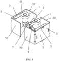
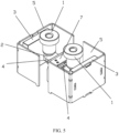
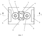
- a high-voltage DC relay for enhancing arc extinguishing capability of the present disclosure includes two static contact leading-out terminals 1 and one movable contact piece 2.
- the movable contact piece 2 is arranged under the two static contact leading-out terminals 1, and two ends of the movable contact piece 2 used as movable contacts are respectively matched with bottom ends of the two static contact leading-out terminals 1 used as static contacts.
- First permanent magnets 3 are respectively arranged at outer side of two ends of the movable contact piece 2 in a longitudinal direction, corresponding to a position where the movable contacts are in contact with the static contacts, and sides having polarity of the two first permanent magnets 3 face the corresponding movable contacts respectively.
- Second permanent magnets 4 are respectively arranged at positions where the movable contacts are in contact with the static contacts, between the two static contact leading-out terminals 1, on the movable contact piece 2.
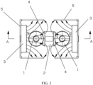
- the side having polarity of the second permanent magnet 4 faces the side having polarity of the corresponding first permanent magnet 3, and polarity of the side of the second permanent magnet 4 facing the movable contacts is opposite to polarity of the side of the first permanent magnet 3 facing the movable contacts.
- a magnetic polarity of the side (i.e., a right face) of the first permanent magnet 3 facing the movable contacts corresponding to one end (left end) of the movable contact piece 2 is a N pole
- a magnetic polarity of the side (i.e., a left face) of the first permanent magnet 3 facing the contacts corresponding to the other end (right end) of the movable contact piece 2 is also a N pole.
- a side having polarity (i.e., a left face) of the second permanent magnet 4 corresponding to one end (left end) of the movable contact piece 2 faces a side having polarity (i.e., a right side) of the corresponding first permanent magnet 3, the polarity of the left face of the second permanent magnet 4 is opposite to the polarity of the right face of the first permanent magnet 3, and the magnetic polarity of the left face of the second permanent magnet 4 at the left end of the movable contact piece 2 is a S pole; similarly, the magnetic polarity of the right face of the second permanent magnet 4 corresponding to the other end (right end) of the movable contact piece 2 is a S pole.
- magnetic field lines of the first permanent magnet 3 radiate to the right, since the S pole of the second permanent magnet 4 is at the right side of the static contact leading-out terminals 1 on the left side, the magnetic field lines of the first permanent magnet 3 gather at a center of the static contact leading-out terminals 1 on the left side, which can enhance the magnetic field intensity of the first permanent magnet 3 at the position where the movable contacts are in contact with the static contacts, especially at the center of the leading-out terminals (i.e. the arc starting point), and accelerate the arc extinguishing speed by magnetic blowing at the moment of starting the arc.
- the magnetic field lines of the first permanent magnet 3 radiate to the left, since the S pole of the second permanent magnet 4 is at the left side of the static contact leading-out terminals 1 on the right side, the magnetic field lines of the first permanent magnet 3 gather at a center of the static contact leading-out terminals 1 on the right side.
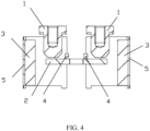
- the magnetic pole surface of the second permanent magnet 4 is smaller than the magnetic pole surface of the first permanent magnet 1, that is, the first permanent magnet 1 is a large permanent magnet and the second permanent magnet 4 is a small permanent magnet.
- the movable contact piece 2 corresponds to a middle portion of the first permanent magnet 3 in a height direction.
- the two second permanent magnets 4 are symmetrically arranged on two sides of a center line of the movable contact piece 2 in a length direction.
- the second permanent magnet 4 is stuck and fixed above the movable contact piece 2, of course, also be above the movable contact piece, a groove recessed downwardly is arranged at a position corresponding to the second permanent magnet, and a portion of the bottom of the second permanent magnet is embedded into the groove.
- the second permanent magnet 4 may be stuck and fixed under the movable contact piece 2, or under the movable contact piece, a groove recessed upwardly is arranged at a position corresponding to the second permanent magnet, and a portion of the top of the second permanent magnet is embedded into the groove.
- the two second permanent magnets 3 are two separate parts, and there is a preset space between the two second permanent magnets 3.
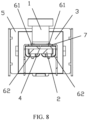
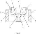
- the high-voltage DC relay further includes two first U-shaped yokes 5 respectively arranged on two first permanent magnets 3, wherein the bottom walls 51 of the two first U-shaped yokes 5 are respectively in contact with one side of the corresponding first permanent magnet 3 facing away from the corresponding movable contacts (the S pole of the first permanent magnet 3 in this embodiment), and the two side walls 52 of the two first U-shaped yokes 5 are respectively arranged on two sides of the movable contact piece 2 in a width direction, and are opposite to the corresponding movable contacts.
- a second permanent magnet 4 is arranged at a position where the movable contacts are in contact with the static contacts, between the two static contact leading-out terminals, and a side having polarity of the second permanent magnet 4 faces a side having polarity of the corresponding first permanent magnet, and polarity of which is opposite to the polarity of a side of the first permanent magnet 3 facing the movable contacts.
- the second permanent magnet 4 due to the specific position where the second permanent magnet 4 is position, magnetic field intensity of a horizontal magnetic field of the first permanent magnet 3 at a position where the movable contacts are in contact with the static contacts (i.e., changing the direction of the original magnetic field), especially at a center of the leading-out terminals (i.e., the arc starting point) can be enhanced, and the arc extinguishing speed by magnetic blowing at a moment of starting arc can be accelerated.
- a high-voltage DC relay for enhancing arc extinguishing capability disclosed in this embodiment is different from that in the first embodiment in that an anti-short circuit structure is arranged in a middle portion of the movable contact piece 2 in a length direction, and the anti-short circuit structure is in a preset space between two second permanent magnets 4.
- the anti-short-circuit structure is an anti-short circuit ring 6.
- the anti-short circuit ring 6 is formed by the cooperation of two " "-shaped upper armatures 61 and two U-shaped lower armatures 62.
- a through hole penetrating through a thickness of the movable contact piece 2 is arranged in the middle portion of the movable contact piece 2 in a longitudinal direction.
- the two " " "-shaped upper armatures 61 are usually fixed on a top of the U-shaped bracket 7 of a pushing rod of the relay by riveting or welding, and two U-shaped lower armatures 62 are respectively fixed to the movable contact piece 2 by riveting, and side walls of the two U-shaped lower armatures 62 pass through the through hole of the movable contact piece 2, and top ends of the two U-shaped lower armatures 62 are exposed out of an upper surface of the movable contact piece, to be cooperated with the two " "-shaped upper armatures 61.
- a closed magnetic circuit is formed in an annular piece formed by the " "-shaped upper armature 61 and the U-shaped lower armature 62 by using an annular magnetic field generated by the movable contact piece, and a suction force is generated to act on the movable contact piece 2, so as to achieve a purpose of resisting the electro-dynamic repulsion force.
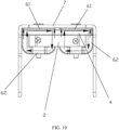
- the anti-short circuit ring 6 of this embodiment has two magnetic circuits, so that the magnetic circuit is not easily saturated, the more the pressure of the contacts increases, the more the suction force of the magnetic circuits generates.
- the second permanent magnet 4 there is a second permanent magnet 4 next to the anti-short circuit ring 6, as shown in Fig. 10 , the second permanent magnet 4 has two sides acting on the magnetic field, on the one hand, the suction force of the anti-short circuit ring 6 (embodied on the left sides of the two anti-short circuit rings 6 in Fig. 10 ) can be enhanced; on the other hand, the repulsion force of the second permanent magnet 4 can weaken the suction force of the anti-short circuit ring 6 (embodied on the right sides of the two anti-short circuit rings 6 in Fig. 10 ).
- an anti-short circuit structure i.e., the anti-short circuit ring 6, is also arranged in the middle portion of the movable contact piece 2 in a length direction.
- the anti-short ring 6 is in a preset space between the two second permanent magnets 4.
- a small permanent magnet 4 i.e., the second permanent magnet
- two large permanent magnets 3 i.e. the first permanent magnets.
- the magnetic field of the large permanent magnet will affect the anti-short circuit effect of the anti-short circuit structure, but if there is the small permanent magnet, the small permanent magnet has a magnetic suction effect on the magnetic field of the large permanent magnet, so as to prevent the magnetic field of the large permanent magnet from influencing the anti-short circuit structure.
Landscapes
- Physics & Mathematics (AREA)
- Electromagnetism (AREA)
- Arc-Extinguishing Devices That Are Switches (AREA)
Applications Claiming Priority (2)
| Application Number | Priority Date | Filing Date | Title |
|---|---|---|---|
| CN202122196800.3U CN216120109U (zh) | 2021-09-10 | 2021-09-10 | 一种可增强灭弧能力的高压直流继电器 |
| PCT/CN2022/116780 WO2023036062A1 (fr) | 2021-09-10 | 2022-09-02 | Relais à courant continu (dc) à haute tension capable d'améliorer la capacité d'extinction d'arc |
Publications (2)
| Publication Number | Publication Date |
|---|---|
| EP4401106A1 true EP4401106A1 (fr) | 2024-07-17 |
| EP4401106A4 EP4401106A4 (fr) | 2025-01-22 |
Family
ID=80732831
Family Applications (1)
| Application Number | Title | Priority Date | Filing Date |
|---|---|---|---|
| EP22866525.3A Pending EP4401106A4 (fr) | 2021-09-10 | 2022-09-02 | Relais à courant continu (dc) à haute tension capable d'améliorer la capacité d'extinction d'arc |
Country Status (6)
| Country | Link |
|---|---|
| US (1) | US20240379300A1 (fr) |
| EP (1) | EP4401106A4 (fr) |
| JP (1) | JP7816678B2 (fr) |
| KR (1) | KR102901684B1 (fr) |
| CN (1) | CN216120109U (fr) |
| WO (1) | WO2023036062A1 (fr) |
Families Citing this family (2)
| Publication number | Priority date | Publication date | Assignee | Title |
|---|---|---|---|---|
| CN216120109U (zh) * | 2021-09-10 | 2022-03-22 | 厦门宏发电力电器有限公司 | 一种可增强灭弧能力的高压直流继电器 |
| CN118801065B (zh) * | 2024-07-19 | 2025-02-18 | 北京雷格讯电子股份有限公司 | 一种双刀四掷开关驱动结构及驱动方法 |
Family Cites Families (14)
| Publication number | Priority date | Publication date | Assignee | Title |
|---|---|---|---|---|
| US4835502A (en) * | 1988-09-13 | 1989-05-30 | Potter & Brumfield, Inc. | Secure magnet blowout mounting for relays |
| KR20130018733A (ko) * | 2010-03-25 | 2013-02-25 | 파나소닉 주식회사 | 접점 장치 |
| CN102129935B (zh) * | 2011-03-10 | 2013-01-02 | 二一三电器深圳有限公司 | 无极性直流接触器灭弧系统 |
| JP2016012505A (ja) * | 2014-06-30 | 2016-01-21 | 富士電機機器制御株式会社 | 接点機構及びこれを使用した電磁接触器 |
| FR3060194B1 (fr) * | 2016-12-09 | 2021-01-15 | Socomec Sa | Dispositif de coupure electrique equipe d'un module magnetique pour le soufflage de l'arc electrique |
| US11670472B2 (en) * | 2018-11-09 | 2023-06-06 | Xiamen Hongfa Electric Power Controls Co., Ltd. | Direct-current relay resistant to short-circuit current |
| CN109559939B (zh) * | 2018-11-09 | 2024-05-14 | 厦门宏发电力电器有限公司 | 一种抗短路电流的直流继电器 |
| CN109659198B (zh) * | 2018-12-28 | 2024-05-14 | 厦门宏发电力电器有限公司 | 一种灭弧及抗短路电流的直流继电器 |
| KR102795563B1 (ko) * | 2019-06-18 | 2025-04-15 | 엘에스일렉트릭(주) | 직류 릴레이 |
| CN210467675U (zh) * | 2019-10-28 | 2020-05-05 | 昆山联滔电子有限公司 | 一种直流灭弧装置及直流继电器 |
| CN113808884B (zh) * | 2021-07-16 | 2024-11-12 | 厦门宏发电力电器有限公司 | 一种可纵向拉弧的高压直流继电器 |
| CN113178359B (zh) * | 2021-02-26 | 2025-08-12 | 厦门宏发电力电器有限公司 | 一种带磁钢灭弧的高压直流继电器 |
| CN216120109U (zh) * | 2021-09-10 | 2022-03-22 | 厦门宏发电力电器有限公司 | 一种可增强灭弧能力的高压直流继电器 |
| CN216435800U (zh) * | 2021-10-26 | 2022-05-03 | 厦门宏发电力电器有限公司 | 一种带抗短路结构的高压直流继电器 |
-
2021
- 2021-09-10 CN CN202122196800.3U patent/CN216120109U/zh active Active
-
2022
- 2022-09-02 WO PCT/CN2022/116780 patent/WO2023036062A1/fr not_active Ceased
- 2022-09-02 KR KR1020247008344A patent/KR102901684B1/ko active Active
- 2022-09-02 EP EP22866525.3A patent/EP4401106A4/fr active Pending
- 2022-09-02 US US18/690,606 patent/US20240379300A1/en active Pending
- 2022-09-02 JP JP2024515409A patent/JP7816678B2/ja active Active
Also Published As
| Publication number | Publication date |
|---|---|
| CN216120109U (zh) | 2022-03-22 |
| KR102901684B1 (ko) | 2025-12-18 |
| KR20240040122A (ko) | 2024-03-27 |
| WO2023036062A1 (fr) | 2023-03-16 |
| US20240379300A1 (en) | 2024-11-14 |
| JP2024530820A (ja) | 2024-08-23 |
| EP4401106A4 (fr) | 2025-01-22 |
| JP7816678B2 (ja) | 2026-02-18 |
Similar Documents
| Publication | Publication Date | Title |
|---|---|---|
| US12562320B2 (en) | High-voltage DC relay with permanent magnet arc extinguishing function | |
| KR20250121614A (ko) | 단락 전류에 견디고 소호할 수 있는 직류 릴레이 | |
| CN212032959U (zh) | 一种可抗短路电流的直流继电器 | |
| KR20230147194A (ko) | 릴레이 | |
| KR20140022054A (ko) | 접점 기구 및 이것을 사용한 전자 접촉기 | |
| EP4141903B1 (fr) | Relais | |
| US20240379300A1 (en) | High-voltage direct current (dc) relay capable of enhancing arc extinguishing capability | |
| KR20140003390A (ko) | 전자 개폐기 | |
| KR102898141B1 (ko) | 릴레이 접촉자 자기차폐 구조 및 릴레이 | |
| KR102087468B1 (ko) | 전자 접촉기 | |
| CN208045411U (zh) | 一种高压直流接触器 | |
| CN113178359B (zh) | 一种带磁钢灭弧的高压直流继电器 | |
| CN220526778U (zh) | 一种隔弧结构、接触单元和继电器 | |
| CN104718591B (zh) | 触点装置及使用该触点装置的电磁开闭器 | |
| JP2024133031A (ja) | リレー | |
| CN215869142U (zh) | 可纵向拉弧的高压直流继电器 | |
| CN113808884B (zh) | 一种可纵向拉弧的高压直流继电器 | |
| CN214956663U (zh) | 新型抗熔焊无极性直流接触器 | |
| CN224266967U (zh) | 一种接触器及电路系统 | |
| CN113161202A (zh) | 新型抗熔焊无极性直流接触器 | |
| CN216435773U (zh) | 具有增磁组件的触头系统、断路器和隔离开关 | |
| CN217035552U (zh) | 一种磁钢灭弧的高压直流继电器 | |
| CN220627644U (zh) | 一种桥式双断点触头独立灭弧结构 | |
| CN221262245U (zh) | 一种继电器 | |
| CN110010416B (zh) | 一种抗洛仑兹力继电器 |
Legal Events
| Date | Code | Title | Description |
|---|---|---|---|
| STAA | Information on the status of an ep patent application or granted ep patent |
Free format text: STATUS: THE INTERNATIONAL PUBLICATION HAS BEEN MADE |
|
| PUAI | Public reference made under article 153(3) epc to a published international application that has entered the european phase |
Free format text: ORIGINAL CODE: 0009012 |
|
| STAA | Information on the status of an ep patent application or granted ep patent |
Free format text: STATUS: REQUEST FOR EXAMINATION WAS MADE |
|
| 17P | Request for examination filed |
Effective date: 20240326 |
|
| AK | Designated contracting states |
Kind code of ref document: A1 Designated state(s): AL AT BE BG CH CY CZ DE DK EE ES FI FR GB GR HR HU IE IS IT LI LT LU LV MC MK MT NL NO PL PT RO RS SE SI SK SM TR |
|
| DAV | Request for validation of the european patent (deleted) | ||
| DAX | Request for extension of the european patent (deleted) | ||
| A4 | Supplementary search report drawn up and despatched |
Effective date: 20241219 |
|
| RIC1 | Information provided on ipc code assigned before grant |
Ipc: H01H 50/54 20060101ALN20241216BHEP Ipc: H01H 1/54 20060101ALN20241216BHEP Ipc: H01H 9/44 20060101ALI20241216BHEP Ipc: H01H 50/16 20060101AFI20241216BHEP |
|
| STAA | Information on the status of an ep patent application or granted ep patent |
Free format text: STATUS: EXAMINATION IS IN PROGRESS |
|
| 17Q | First examination report despatched |
Effective date: 20250717 |