EP4401108A1 - Clip de fusible de secours - Google Patents
Clip de fusible de secours Download PDFInfo
- Publication number
- EP4401108A1 EP4401108A1 EP23220805.8A EP23220805A EP4401108A1 EP 4401108 A1 EP4401108 A1 EP 4401108A1 EP 23220805 A EP23220805 A EP 23220805A EP 4401108 A1 EP4401108 A1 EP 4401108A1
- Authority
- EP
- European Patent Office
- Prior art keywords
- fuse
- clip
- track
- underhang
- spare
- Prior art date
- Legal status (The legal status is an assumption and is not a legal conclusion. Google has not performed a legal analysis and makes no representation as to the accuracy of the status listed.)
- Granted
Links
Images



Classifications
-
- H—ELECTRICITY
- H01—ELECTRIC ELEMENTS
- H01H—ELECTRIC SWITCHES; RELAYS; SELECTORS; EMERGENCY PROTECTIVE DEVICES
- H01H85/00—Protective devices in which the current flows through a part of fusible material and this current is interrupted by displacement of the fusible material when this current becomes excessive
- H01H85/02—Details
- H01H85/20—Bases for supporting the fuse; Separate parts thereof
-
- H—ELECTRICITY
- H01—ELECTRIC ELEMENTS
- H01H—ELECTRIC SWITCHES; RELAYS; SELECTORS; EMERGENCY PROTECTIVE DEVICES
- H01H85/00—Protective devices in which the current flows through a part of fusible material and this current is interrupted by displacement of the fusible material when this current becomes excessive
- H01H85/02—Details
- H01H85/20—Bases for supporting the fuse; Separate parts thereof
- H01H85/2045—Mounting means or insulating parts of the base, e.g. covers, casings
-
- H—ELECTRICITY
- H01—ELECTRIC ELEMENTS
- H01H—ELECTRIC SWITCHES; RELAYS; SELECTORS; EMERGENCY PROTECTIVE DEVICES
- H01H85/00—Protective devices in which the current flows through a part of fusible material and this current is interrupted by displacement of the fusible material when this current becomes excessive
- H01H85/02—Details
- H01H85/22—Intermediate or auxiliary parts for carrying, holding, or retaining fuse, co-operating with base or fixed holder, and removable therefrom for renewing the fuse
-
- H—ELECTRICITY
- H01—ELECTRIC ELEMENTS
- H01H—ELECTRIC SWITCHES; RELAYS; SELECTORS; EMERGENCY PROTECTIVE DEVICES
- H01H85/00—Protective devices in which the current flows through a part of fusible material and this current is interrupted by displacement of the fusible material when this current becomes excessive
- H01H85/02—Details
- H01H85/26—Magazine arrangements
- H01H85/263—Magazine arrangements with spare printed circuit fuse
-
- H—ELECTRICITY
- H01—ELECTRIC ELEMENTS
- H01H—ELECTRIC SWITCHES; RELAYS; SELECTORS; EMERGENCY PROTECTIVE DEVICES
- H01H85/00—Protective devices in which the current flows through a part of fusible material and this current is interrupted by displacement of the fusible material when this current becomes excessive
- H01H85/02—Details
- H01H85/20—Bases for supporting the fuse; Separate parts thereof
- H01H2085/2065—Bases for supporting the fuse; Separate parts thereof with base contacts adapted or adaptable to fuses of different lenghts; bases with self-aligning contacts; intermediate adaptation pieces
-
- H—ELECTRICITY
- H01—ELECTRIC ELEMENTS
- H01H—ELECTRIC SWITCHES; RELAYS; SELECTORS; EMERGENCY PROTECTIVE DEVICES
- H01H85/00—Protective devices in which the current flows through a part of fusible material and this current is interrupted by displacement of the fusible material when this current becomes excessive
- H01H85/02—Details
- H01H85/0208—Tools for inserting and removing fuses
-
- H—ELECTRICITY
- H01—ELECTRIC ELEMENTS
- H01H—ELECTRIC SWITCHES; RELAYS; SELECTORS; EMERGENCY PROTECTIVE DEVICES
- H01H85/00—Protective devices in which the current flows through a part of fusible material and this current is interrupted by displacement of the fusible material when this current becomes excessive
- H01H85/02—Details
- H01H85/20—Bases for supporting the fuse; Separate parts thereof
- H01H85/203—Bases for supporting the fuse; Separate parts thereof for fuses with blade type terminals
-
- H—ELECTRICITY
- H01—ELECTRIC ELEMENTS
- H01H—ELECTRIC SWITCHES; RELAYS; SELECTORS; EMERGENCY PROTECTIVE DEVICES
- H01H85/00—Protective devices in which the current flows through a part of fusible material and this current is interrupted by displacement of the fusible material when this current becomes excessive
- H01H85/02—Details
- H01H85/26—Magazine arrangements
Definitions
- Embodiments of the present disclosure relate to fuse holders and, more particularly, for fuse holders that accommodate spare fuses.
- Fuses are current-sensitive devices designed to be the intentional weak link in an electrical circuit. Fuses come in a variety of form factors, including bolt-down fuses.
- Bolt-down fuses feature a fuse body with two terminals extending therefrom, where one or more of the terminals is bolted down to a surface, such as a busbar or printed circuit board (PCB).
- PCB printed circuit board
- fuse holders which are a generally airtight housing for the fuse.
- the fuse holder may have busbars or PCBs therein, with cables extending from the fuse to the circuit(s) to be protected.
- More extensive fuse holders may include low-voltage power distribution modules and high-voltage power distribution units, which house relays in addition to fuses.
- the housing of the fuse holder may be a clam-shell type, with a cover portion already connected to the housing, or the fuse holder may have a separate cover, due to the fact that the fuse holder needs to be accessed when changing the fuse.
- the fuse holder will also house one or more spare fuses.
- the typical arrangement is to have the spare fuses bolted down to the housing, which necessitates that the housing be sized to accommodate the particular fuse size. There is also the possibility that the bolts will get lost during the fuse change operation.
- the fuse housing may also have a plug-in arrangement for holding spare fuses, which does not successfully accommodate fuses of different sizes.
- An exemplary embodiment of a fuse holder in accordance with the present disclosure may include a housing, a clip, and a cover.
- the housing is for a fuse, and the fuse is to be connected to and protecting a circuit.
- the clip includes a base, a pair of shafts, an overhead, and an underhang.
- the base is for seating a spare fuse.
- the pair of shafts are on and perpendicular to the base.
- the overhead is located on and supported by the pair of shafts.
- the underhang is beneath the overhang and deforms in response to the movement of the spare fuse along the base toward the shaft.
- the cover is placed over the housing to form an enclosed space around the fuse and the clip.
- An exemplary embodiment of a clip in accordance with the present disclosure may include a shaft, an overhead, and an underhang.
- the shaft is located on and perpendicular to a base.
- the overhead is on and supported by the shaft and is triangular prism-shaped.
- the underhang is attached to the overhead. The underhang and the base secure a spare fuse.
- a fuse holder for holding working fuses features a spare fuse holder inside the housing of the fuse holder.
- the spare fuse holder includes a clip that has an elastic underhang for exerting pressure on the fuse as it is slid into place in the clip.
- the clip also has a base with some angled surfaces, two shafts orthogonal to the base for providing structural support, and, between the shafts, a fuse release for enabling ease of removal of the spare fuse.
- the spare fuse holder is suitable for bolt-down fuses with various current ratings. Unlike the bolt-down type, the spare fuse holder does not use bolts for holding the spare fuse. Unlike the plug-in type, the spare fuse holder successfully holds fuses of different fuse body sizes, terminal sizes, and current ratings.
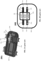
- FIG. 1 is a representative drawing of a fuse holder 100 (perspective view) for holding fuses and spare fuses, according to exemplary embodiments.
- the fuse holder 100 includes a housing 108 to hold two fuses 102a and 102b (collectively, "fuses 102").
- the fuses 102 are bolt-down fuses.
- the fuse holder 100 also features a busbar 104 which is distributed in several locations in the fuse holder 100.
- the fuses 102 are each connected at one end to the busbar 104.
- Bolts 106a-c (collectively, “bolts 106") enable connections to be made between the fuse holder 100 and one or more cables or other busbars (not shown).
- Clamps 112a-d (collectively, “clamps 112") enable a cover to be attached to the housing 108, thus ensuring that there is a somewhat air-tight seal for the contents inside the fuse holder 100.
- Mounting brackets 114a-b (collectively, “mounting brackets 114") include apertures for bolting the fuse holder 100 to a surface, although the mounting brackets may be attached to the surface in another way, as this is a non-limiting example.
- the fuse holder 100 features a spare fuse holder 110, shown in the dashed circle.
- the spare fuse holder 110 overcomes the deficiencies of the prior art by accommodating fuses of different sizes.
- the spare fuse holder 110 holds bolt-down fuses, although the design is not limited in this respect.
- the spare fuse holder 110 is flexible enough to accommodate a variety of different fuse types and shapes.
- FIGs. 2A-2E are representative drawings of fuse holders and bolt-down fuses, according to the prior art.
- FIG. 2A is a perspective view of a first fuse holder 200A
- FIG. 2B is an overhead view of a second fuse holder 200B
- FIGs. 2C-2E are perspective views of bolt-down fuses 20a-c (collectively, "spare fuse holders 200" and "bolt-down fuses 202").
- the fuse holders 200 do not include the fuses, busbars, bolts, and clamps that characterize typical fuse holders, as these drawings are intended to show and describe the spare fuse holder portion of these devices.
- a fuse 202a is disposed in the fuse holder 200A ( FIG. 2A ), fuses 202b and 202c are disposed in the fuse holder 200B ( FIG. 2B ), and fuses 202d ( FIG. 2C ), 202e ( FIG. 2D ), and 202f ( FIG. 2E ) are shown (collectively, "fuses 202").
- Each fuse 202 includes a fuse body and two terminals, with fuse 202a having terminal 210a, fuse body 212a and terminal 210b ( FIG. 2A ), fuse 202b having terminal 210c, fuse body 212b, and terminal 210d, fuse 202c having terminal 210e, fuse body 212c, and terminal 210f ( FIG.
- terminal 210 having terminal 210g, fuse body 212d, and terminal 210h ( FIG. 2C ), fuse 202e having terminal 210i, fuse body 212e, and terminal 210j ( FIG. 2D ), and fuse 202f having terminal 210k, fuse body 212f, and terminal 2101 ( FIG. 2E ) (collectively, “terminals 210" and "fuse bodies 212").
- the fuse holder 200A features a housing 208a with a location for placing the spare fuse 202a.
- the fuse holder 200 holds the spare fuse 202a using bolts 204a and 204b (collectively, "bolts 204").
- the fuse holder 200A is thus a "screwing design" of fuse holder since the bolts 204 are screwed into the housing 208a to secure the spare fuse 202a.
- the housing 208a would be assembled with the specific dimensions of the fuse 202a in mind.
- a screwdriver would be needed to remove the bolts 204 and there is some risk that the bolts would be lost during this process. Further, having the bolts will result in additional assembly time including the process of securing the spare fuse.
- the fuse holder 200B features a housing 208b with a fuse receptacle 206 suitable for holding the two fuses 202b and 202c.
- the fuse holder 200B is thus a "plug-in design" of fuse holder, since the fuses 202b and 202c are simply plugged into the fuse receptacle 206 (no bolts are needed).
- the fuse receptacle 206 includes four terminal holders 216a-d (collectively, "terminal receptacles 216”), one for each terminal 210 of the two fuses.
- the terminal holders 216 are designed to clamp the terminals 210 so that the fuses 202 stay in place in the fuse receptacle 206.
- the fuse 202b is larger than the fuse 202c and, due to a difference in current rating between the two fuses, the terminals 210c and 210d are longer and thicker than the terminals 210e and 210f. Although able to hold both fuses 202b and 202c, the terminals holders 216 of the fuse receptacle 206 are all the same size. Thus, the fuse receptacle is sized for the larger fuse 202b and the terminal holder 216a successfully clamps the terminal 210c of the fuse 202b while the terminal holder 216c successfully clamps the terminal 210d of the fuse 202b.
- the fuse 202c may not be fully clamped by respective terminal holders 216b and 216d of the fuse receptacle 206.
- the smaller fuse 202c may fall out of the fuse receptacle 206, such as when a cover (not shown) is removed from the housing 208b of the fuse holder 200B, which is not a desired outcome.
- the fuse receptacle 206 of the fuse holder 200B could be designed differently. That is, the terminal holders 216b and 216d could be made smaller, for fuses of lower current rating. This, however, limits the fuses that can be accepted by the fuse receptacle 206, which is also not a desired outcome.
- the three bolt-down fuses 202d, 202e, and 202f of FIGs. 2C-2E may be suitable for either the screwing design fuse holder 200A or the plug-in design fuse holder 200B. Although similar in shape, there are some differences between the bolt-down fuses 202d, 202e, and 202f.
- the terminals 210i and 210j (of bolt-down fuse 202e) and the terminals 210k and 2101 (of bolt-down fuse 202f) each have apertures, with terminal 210i having aperture 214b, terminal 210j having aperture 214c, terminal 210k having aperture 214d, and terminal 2101 having aperture 214e.
- terminal 210g has an aperture 214a (collectively, "apertures 214"), but terminal 210h has no aperture.
- the bolt-down fuse 202d would not be suitable for the fuse holder 200A, as the spare fuse is affixed to the housing 208a using two bolts 204.
- the bolt-down fuses 202d, 202e, and 202f are different sizes and have different current ratings.
- the bolt-down fuses 202d-f may not be suitable for the fuse holder 200B.
- FIGs. 3A-3B are representative drawings of the fuse holder 100 of FIG. 1 , according to exemplary embodiments.
- FIG. 3A is a perspective view and FIG. 3B is a close-up cross-sectional perspective view of the fuse holder 100.
- the fuse holder 100 is an improvement over the prior art fuse holders 200 in several respects.
- the fuse holder 100 features a special clip design to hold spare fuses. Compared with the legacy bolt-down and plug-in fuse holders, the fuse holder 100 is more versatile, as the special clip design can support a variety of types of bolt-down fuses.
- the fuse holder 100 can support bolt-down fuses having different sizes and current ratings, as well as supporting bolt-down fuses having single-aperture terminals such as the bolt-down fuse 202d ( FIG. 2C ). Further, in some embodiments, the fuse holder 100 can support fuses other than bolt-down fuses.
- the spare fuse holder 110 introduced in FIG. 1 is shown in FIGs. 3A and 3B .
- the fuse 102 which is not a replacement fuse, but is a fuse being used to protect a circuit connected to the fuse holder 100, is also shown in FIG. 3A .
- the position of the spare fuse holder 110 may differ from what is shown in FIGs. 1 , 3A, and 3B , in a non-limiting embodiment.
- a cover 302 is placed over the housing 108 to form an enclosed spaced which encapsulates both the fuse 102 and the spare fuse holder 110.
- the housing 108 and cover 302 are plastic.
- the fuse holder 100 includes a seal 304 which surrounds the perimeter of a top portion of the housing 108.
- the seal 304 may surround the perimeter of a top portion of the cover 302.
- the seal 304 is elastomeric and provides an airtight enclosed space for the fuse 102 and the spare fuse holder 110.
- the spare fuse holder 110 includes a clip 308 and a fuse 306.
- the fuse 306 is shown as a rectangular cube to represent a generalized shape of the body of a fuse, such as one of the fuse bodies 212 shown in FIGs. 2C-2E .
- the clip 308 is capable of holding any thickness of fuses tightly.
- the fuses are easy to load and unload and are particularly more convenient than the bolt-down spare fuse holders.
- the spare fuse holder 110 is capable of holding a fuse having a fuse body of up to 12mm with stability. Further, the design of the spare fuse holder 110 can be scaled for larger fuses, including high-voltage fuses, in some embodiments.
- FIG. 4A-4F are representative drawings of the spare fuse holder 110 that is part of the fuse holder 100 of FIG. 1 , according to exemplary embodiments.
- FIG. 4A is a side cross-sectional view of the spare fuse holder 110 before the fuse is installed (clip is in a resting state)
- FIG. 4B is a side view of the spare fuse holder after the fuse is installed (clip is in holding state)
- FIG. 4C is a perspective view of the spare fuse holder with the fuse installed
- FIG. 4D is a perspective view of the clip without the fuse
- FIG. 4E is a cross-sectional perspective view of the clip
- FIG. 4F is a side view of the spare fuse holder with the fuse installed (clip is in holding state).
- the clip 308 features a base 402, a pair of shafts 406a-b (collectively, "shafts 406"), and an overhead 404, with both shafts being visible in FIG. 4D .
- the base 402 is for seating the spare fuse 306 and the shafts are orthogonal (perpendicular) to the base and support the overhead.
- the overhead 404 has three sides 432, 434, and 436 which form a triangular prism. From the side, such as in the views of FIGs.
- the overhead 404 resembles a right triangle, with a first side 432 (bottom, horizontal side) being an extension of the shaft 406, a second side 434 (vertical side) being perpendicular to the first side, and the third side 436 (right-angled side) being angled.
- the third side 436 is at a 45° angle relative to the first side 432 and the second side 434.
- the overhead 404 further has an opening 416 that cuts away the central part of the first side 432 and the third side 436, exposing an inner portion of the second side 434.
- the overhead 404 is a hollowed out triangular prism.
- An underhang 412 is disposed beneath and attached to the overhead 404. As shown particularly in the cross-sectional view of FIG. 4E , the underhang 412 extends downward from the side 432 of the overhead 404, and is curved so that, except for the end connection to the overhead, is substantially parallel to the side 432 in its resting state.
- the underhang 412 is an elastomeric material having the ability to deform its shape in reaction to pressure, e.g., the pressure coming from the top of the spare fuse 306, which causes the underhang 412 to compress toward the overhang 404, e.g., in an upward direction.
- both the underhang 412 and the overhead 404 are elastomeric.
- a fuse release 414 Beneath the third side 434 of the overhang 404 and disposed between the shafts 406 is a fuse release 414.
- the fuse release 414 is most visible in FIG. 4A , as only the shaft 406b is visible.
- the fuse release 414 extends downward from the side 434 of the overhead 404.
- the fuse release 414 has an angular side that juts out from the back of the clip 308, making it easy to push the fuse release, and a second curved side opposite the angular side that pushes against the fuse body 422 when the fuse release 414 is pushed (depressed) toward the region in between the two shafts 406.
- the fuse release 414 pushes the spare fuse 306 away from the pair of shafts 406, causing the spare fuse to be released from the clip 308.
- the fuse release 414 is an elastomeric material having the ability to deform its shape in reaction to pressure. By being pressed, the fuse release 414 moves toward the installed spare fuse 306, which causes the spare fuse 306 to move out from under the clip 308.
- the base 402 consists of three surfaces, a surface 420a, a surface 420b, and a surface 420c (collectively, “surfaces 420"). Although substantially planar to one another, the surfaces 420a and 420b are angled slightly, to facilitate leading the spare fuse 306 to the clip 308. Extending across the surfaces, 420 are two tracks 408a and 408b (collectively, “tracks 408"). The tracks 408 are rectangular cutouts which are perpendicular to the surfaces 420, are disposed adjacent two opposing sides ends of the base 402, and have a depth that is slightly less than the height, h, of the base 402.
- Each track 408 has a fuse clip, with track 408a having fuse clip 418a and track 408b having fuse clip 418b (collectively, "fuse clips 418").
- the fuse clips 418 are close to the side of the tracks 408 that are adjacent the shafts 406.
- the fuse clips 418 have an angled tip portion 426 ( FIG. 4E ) that, when pressed, will cause each fuse clip to move into the cavity (channel) of its respective track 408. In the illustrated embodiments, the movement of each fuse clip 418 would be downward into the respective tracks 408.
- a close-up view of the angled tip portion 426 is shown in FIG. 5D , below.
- the depths of the tracks 408 are slightly greater than a height, h 2 , of the angled tip portion 426 of the fuse clips 418 (see FIG. 5D ).
- the fuse clips 418 are elastomeric, in exemplary embodiments.
- the base 402, the shaft 406, the overhead 404, the underhang 412, the fuse release 414, and the fuse clips 418 are made of a thermoplastic material using injection molding operations.
- the overhead 404, underhang 412, the fuse release 414, and the fuse clips 418 are impregnated with an elastomeric material, thus allowing the clip 308 to be both flexible in the impregnated regions and rigid in the other, non-impregnated regions.
- the base 402, shafts 406, and overhead 404 are a support structure for the spare fuse 306.
- the spare fuse 306 is a bolt-down fuse, which has a fuse body 422 and terminals 410a-b (collectively, “terminals 410"), with the fuse body having three portions 424a-c (collectively, "portions 424").
- the track 408a is a distance, d, from the track 408b, where the distance, d, is larger than the width, w , of portions 424a and 424c of the fuse body 422, as the width of portion 424a is substantially similar to the width of portion 424c (see FIG. 4C ).
- the portion 424b is wider than the portions 414a and 424c (see FIG.
- the portion 424b slides over the tracks 408 but the portions 424a and 424c do not slide over the tracks.
- the portion 424b pushes against the angled tip portion 426 of respective fuse clips 418, causing the fuse clips to move downward into respective tracks 408.
- the portion 424a does not contact the fuse clips 418.
- the portion 424b does contact the fuse clips 418 and pushes them down into the tracks 408.
- the portion 424b of the fuse body 422 moves past the fuse clips 418 and the fuse clips move again upward from the tracks 408.
- the angled tip portion 426 of the fuse clips 418 act as a stop to the spare fuse 306.
- the fuse clips 418 may remain in the down position within the tracks 408, in some embodiments. Because the underhang 412 is exerting downward pressure thereon, the spare fuse will nevertheless remain in place within the clip 308.
- the length of the fuse clips 418 or the size and shape of the angled tip portion 426 may be adjusted to support a spare fuse having a different fuse body than the fuse body 422 of the spare fuse 306.
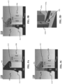
- FIGs. 5A-5D are representative drawings of the spare fuse holder 110 of the fuse holder 100 of FIG. 1 , according to exemplary embodiments.
- FIGs. 5A-5C are side views of the spare fuse holder 110, with FIG. 5A showing a first fuse insertion point (clip is in resting state), FIG. 5B showing a second fuse insertion point (clip is in activated state), and FIG. 5C showing a third fuse insertion point (clip is in holding state), and FIG. 5D is a detailed perspective view of the fuse clip position at the third fuse insertion point.
- FIGs. 5A-5C are side views of the spare fuse holder 110, with FIG. 5A showing a first fuse insertion point (clip is in resting state), FIG. 5B showing a second fuse insertion point (clip is in activated state), and FIG. 5C showing a third fuse insertion point (clip is in holding state), and FIG. 5D is a detailed perspective view of the fuse clip position at the third fuse insertion point.
- the overhead 404 and underhang 412 include cross-hatching to indicate a flexion or pressure-based deformation due to the sliding of the spare fuse 306 toward the shaft 406 of the clip 308.
- the clip 308 is in a resting state when the underhang has not been deformed; the clip is in an activated state when the underhang is deformed and the fuse clips have been pushed into the respective tracks 408; and the clip is in a holding state when the underhang is deformed and the fuse clips are no longer pushed into the respective tracks but have returned to an original position.
- the spare fuse 306 is adjacent, but not yet under the overhead 404 and underhang 412 of the clip 308.
- the portion 424a does not touch the angled tip portions 426 of the fuse clips 418, so the fuse clips remain undisturbed as well.
- the slanted surfaces 420a and 420b of the base 402 are slightly angled, allowing the spare fuse 306 to readily move toward the shafts 406 of the clip 308.
- the spare fuse 306 is moved toward the shaft 406 of the clip 308, and the underhang 412 deforms upward, as the spare fuse is compressing the underhang 412 toward the overhead 404.
- the portion 424a of the fuse body 422 is fully under the underhang 412 and the portion 424b is partially under the underhang. Further, the portion 424b is pushing against the angled tip portion 426 of the fuse clips 418, causing the fuse clips to move downward into their respective tracks 408.
- Both the underhang 412 and the overhead 404 are cross-hatched, indicating some flexion in response to the movement of the spare fuse 306 along the base 402 toward the shaft 406. Although the overhead 404 flexes a little, the shaft 406 of the clip 308 remains rigid, in some embodiments.
- the spare fuse 306 is fully engaged with the clip 308, with portion 424a being flush against the shafts 406.
- portion 424b moves past the angled tip portion 426 of the fuse clips 418, the fuse clips move from a downward position inside the tracks 408 back to the original position.
- the backside of the angled tip portion 426 is flush against the portion 424b of the fuse body 422.
Landscapes
- Fuses (AREA)
Applications Claiming Priority (1)
| Application Number | Priority Date | Filing Date | Title |
|---|---|---|---|
| CN202211721419.7A CN118280786A (zh) | 2022-12-30 | 2022-12-30 | 备用熔断器夹具 |
Publications (2)
| Publication Number | Publication Date |
|---|---|
| EP4401108A1 true EP4401108A1 (fr) | 2024-07-17 |
| EP4401108B1 EP4401108B1 (fr) | 2025-05-07 |
Family
ID=89428863
Family Applications (1)
| Application Number | Title | Priority Date | Filing Date |
|---|---|---|---|
| EP23220805.8A Active EP4401108B1 (fr) | 2022-12-30 | 2023-12-29 | Clip de fusible de secours |
Country Status (3)
| Country | Link |
|---|---|
| US (2) | US12308195B2 (fr) |
| EP (1) | EP4401108B1 (fr) |
| CN (1) | CN118280786A (fr) |
Families Citing this family (1)
| Publication number | Priority date | Publication date | Assignee | Title |
|---|---|---|---|---|
| US20250292985A1 (en) * | 2024-03-12 | 2025-09-18 | Eaton Intelligent Power Limited | Fuse Holding Provision in Fuse Holder Cover |
Citations (3)
| Publication number | Priority date | Publication date | Assignee | Title |
|---|---|---|---|---|
| EP0145088A2 (fr) * | 1983-11-30 | 1985-06-19 | Littelfuse Tracor B.V. | Porte-fusible montable sur un panneau |
| WO2014181655A1 (fr) * | 2013-05-07 | 2014-11-13 | 住友電装株式会社 | Boîtier de connexions électriques |
| CN109494137A (zh) * | 2018-11-27 | 2019-03-19 | 新乡市光明电器有限公司 | 备用保险丝仓及车载保险盒 |
Family Cites Families (6)
| Publication number | Priority date | Publication date | Assignee | Title |
|---|---|---|---|---|
| IT221342Z2 (it) * | 1990-05-31 | 1994-03-04 | Fittings Ind Srl | Portafusibili perfezionato, in particolare per circuiti stampati. |
| US6059609A (en) * | 1997-02-04 | 2000-05-09 | Lear Automotive Dearborn, Inc. | Moveable fuse-holder |
| MXPA06002976A (es) * | 2003-09-17 | 2006-06-14 | Mack Trucks | Cable de bateria con provisiones para la proteccion integral de un circuito. |
| US20070141923A1 (en) * | 2005-12-16 | 2007-06-21 | Rauscher Karl F | Fuse clip |
| JP4408918B2 (ja) * | 2007-07-19 | 2010-02-03 | 本田技研工業株式会社 | ヒューズプラー |
| JP6135014B2 (ja) * | 2013-06-25 | 2017-05-31 | 矢崎総業株式会社 | 予備ヒューズの保持構造 |
-
2022
- 2022-12-30 CN CN202211721419.7A patent/CN118280786A/zh active Pending
-
2023
- 2023-12-28 US US18/398,706 patent/US12308195B2/en active Active
- 2023-12-29 EP EP23220805.8A patent/EP4401108B1/fr active Active
-
2025
- 2025-04-11 US US19/176,511 patent/US20250239428A1/en active Pending
Patent Citations (3)
| Publication number | Priority date | Publication date | Assignee | Title |
|---|---|---|---|---|
| EP0145088A2 (fr) * | 1983-11-30 | 1985-06-19 | Littelfuse Tracor B.V. | Porte-fusible montable sur un panneau |
| WO2014181655A1 (fr) * | 2013-05-07 | 2014-11-13 | 住友電装株式会社 | Boîtier de connexions électriques |
| CN109494137A (zh) * | 2018-11-27 | 2019-03-19 | 新乡市光明电器有限公司 | 备用保险丝仓及车载保险盒 |
Also Published As
| Publication number | Publication date |
|---|---|
| US20250239428A1 (en) | 2025-07-24 |
| CN118280786A (zh) | 2024-07-02 |
| US12308195B2 (en) | 2025-05-20 |
| EP4401108B1 (fr) | 2025-05-07 |
| US20240222061A1 (en) | 2024-07-04 |
Similar Documents
| Publication | Publication Date | Title |
|---|---|---|
| CN112005399B (zh) | 电池模块 | |
| EP4401108B1 (fr) | Clip de fusible de secours | |
| KR101491190B1 (ko) | 케이블 리드-스루 장치 | |
| US7878822B2 (en) | Sealed compact power distribution module | |
| US4767984A (en) | Protective fixture for chip carrier | |
| CN1218427C (zh) | 电池充电和放电系统 | |
| US5080228A (en) | Integral carrier and system for electrical components | |
| CN103038872B (zh) | 用于电子器件的可剥离混合托盘系统 | |
| EP2610943A1 (fr) | Batterie rechargeable comprenant des moyens de compression isolants entre le couvercle piles et procédé d' assemblage de la batterie | |
| EP1505670A2 (fr) | Ensemble batterie et son procédé de fabrication | |
| US20040152355A1 (en) | Electrical connector for securing a wire to a contact | |
| CN101926060A (zh) | 电子组件及其制造方法 | |
| CN1235702A (zh) | 印刷电路板用的电池连接器和电池夹持器 | |
| US20120164878A1 (en) | Rf module | |
| CN114256556B (zh) | 电池模块壳体以及用于将电池组单体电池定位并且固定在电池模块壳体的内部的方法 | |
| KR20190040280A (ko) | 배터리 홀더 | |
| EP4432438A1 (fr) | Boîtier de dispositif électronique avec compartiment de batterie intégré | |
| WO2010011880A1 (fr) | Procédé et appareil permettant de fermer hermétiquement un boîtier | |
| US6753474B2 (en) | Pick and place cover for multiple terminal electronic components | |
| US7037139B1 (en) | Wiretrap electrical connector and assembly with strain relief plate | |
| US6291095B1 (en) | Flexible battery mounting and adjustable battery package | |
| EP3413376B1 (fr) | Bloc-batterie comprenant une butée de plateau permettant de bloquer le rebondissement d'un couvercle de bloc | |
| KR100900979B1 (ko) | 세퍼레이터형 스토퍼 | |
| US20050011055A1 (en) | Open frame tray clip | |
| US12238876B2 (en) | Size-adjustable structure for mounting and protecting electronic device and tank |
Legal Events
| Date | Code | Title | Description |
|---|---|---|---|
| PUAI | Public reference made under article 153(3) epc to a published international application that has entered the european phase |
Free format text: ORIGINAL CODE: 0009012 |
|
| STAA | Information on the status of an ep patent application or granted ep patent |
Free format text: STATUS: THE APPLICATION HAS BEEN PUBLISHED |
|
| AK | Designated contracting states |
Kind code of ref document: A1 Designated state(s): AL AT BE BG CH CY CZ DE DK EE ES FI FR GB GR HR HU IE IS IT LI LT LU LV MC ME MK MT NL NO PL PT RO RS SE SI SK SM TR |
|
| STAA | Information on the status of an ep patent application or granted ep patent |
Free format text: STATUS: REQUEST FOR EXAMINATION WAS MADE |
|
| 17P | Request for examination filed |
Effective date: 20240908 |
|
| RBV | Designated contracting states (corrected) |
Designated state(s): AL AT BE BG CH CY CZ DE DK EE ES FI FR GB GR HR HU IE IS IT LI LT LU LV MC ME MK MT NL NO PL PT RO RS SE SI SK SM TR |
|
| GRAP | Despatch of communication of intention to grant a patent |
Free format text: ORIGINAL CODE: EPIDOSNIGR1 |
|
| STAA | Information on the status of an ep patent application or granted ep patent |
Free format text: STATUS: GRANT OF PATENT IS INTENDED |
|
| RIC1 | Information provided on ipc code assigned before grant |
Ipc: H01H 85/22 20060101ALI20250102BHEP Ipc: H01H 85/20 20060101AFI20250102BHEP |
|
| INTG | Intention to grant announced |
Effective date: 20250121 |
|
| GRAS | Grant fee paid |
Free format text: ORIGINAL CODE: EPIDOSNIGR3 |
|
| GRAA | (expected) grant |
Free format text: ORIGINAL CODE: 0009210 |
|
| STAA | Information on the status of an ep patent application or granted ep patent |
Free format text: STATUS: THE PATENT HAS BEEN GRANTED |
|
| AK | Designated contracting states |
Kind code of ref document: B1 Designated state(s): AL AT BE BG CH CY CZ DE DK EE ES FI FR GB GR HR HU IE IS IT LI LT LU LV MC ME MK MT NL NO PL PT RO RS SE SI SK SM TR |
|
| REG | Reference to a national code |
Ref country code: GB Ref legal event code: FG4D |
|
| REG | Reference to a national code |
Ref country code: CH Ref legal event code: EP |
|
| REG | Reference to a national code |
Ref country code: DE Ref legal event code: R096 Ref document number: 602023003370 Country of ref document: DE |
|
| P01 | Opt-out of the competence of the unified patent court (upc) registered |
Free format text: CASE NUMBER: APP_19552/2025 Effective date: 20250423 |
|
| REG | Reference to a national code |
Ref country code: IE Ref legal event code: FG4D |
|
| REG | Reference to a national code |
Ref country code: NL Ref legal event code: MP Effective date: 20250507 |
|
| PG25 | Lapsed in a contracting state [announced via postgrant information from national office to epo] |
Ref country code: PT Free format text: LAPSE BECAUSE OF FAILURE TO SUBMIT A TRANSLATION OF THE DESCRIPTION OR TO PAY THE FEE WITHIN THE PRESCRIBED TIME-LIMIT Effective date: 20250908 Ref country code: ES Free format text: LAPSE BECAUSE OF FAILURE TO SUBMIT A TRANSLATION OF THE DESCRIPTION OR TO PAY THE FEE WITHIN THE PRESCRIBED TIME-LIMIT Effective date: 20250507 Ref country code: FI Free format text: LAPSE BECAUSE OF FAILURE TO SUBMIT A TRANSLATION OF THE DESCRIPTION OR TO PAY THE FEE WITHIN THE PRESCRIBED TIME-LIMIT Effective date: 20250507 |
|
| REG | Reference to a national code |
Ref country code: LT Ref legal event code: MG9D |
|
| PG25 | Lapsed in a contracting state [announced via postgrant information from national office to epo] |
Ref country code: NO Free format text: LAPSE BECAUSE OF FAILURE TO SUBMIT A TRANSLATION OF THE DESCRIPTION OR TO PAY THE FEE WITHIN THE PRESCRIBED TIME-LIMIT Effective date: 20250807 Ref country code: GR Free format text: LAPSE BECAUSE OF FAILURE TO SUBMIT A TRANSLATION OF THE DESCRIPTION OR TO PAY THE FEE WITHIN THE PRESCRIBED TIME-LIMIT Effective date: 20250808 |
|
| PG25 | Lapsed in a contracting state [announced via postgrant information from national office to epo] |
Ref country code: NL Free format text: LAPSE BECAUSE OF FAILURE TO SUBMIT A TRANSLATION OF THE DESCRIPTION OR TO PAY THE FEE WITHIN THE PRESCRIBED TIME-LIMIT Effective date: 20250507 Ref country code: PL Free format text: LAPSE BECAUSE OF FAILURE TO SUBMIT A TRANSLATION OF THE DESCRIPTION OR TO PAY THE FEE WITHIN THE PRESCRIBED TIME-LIMIT Effective date: 20250507 |
|
| REG | Reference to a national code |
Ref country code: AT Ref legal event code: MK05 Ref document number: 1793452 Country of ref document: AT Kind code of ref document: T Effective date: 20250507 |
|
| PG25 | Lapsed in a contracting state [announced via postgrant information from national office to epo] |
Ref country code: BG Free format text: LAPSE BECAUSE OF FAILURE TO SUBMIT A TRANSLATION OF THE DESCRIPTION OR TO PAY THE FEE WITHIN THE PRESCRIBED TIME-LIMIT Effective date: 20250507 |
|
| PG25 | Lapsed in a contracting state [announced via postgrant information from national office to epo] |
Ref country code: HR Free format text: LAPSE BECAUSE OF FAILURE TO SUBMIT A TRANSLATION OF THE DESCRIPTION OR TO PAY THE FEE WITHIN THE PRESCRIBED TIME-LIMIT Effective date: 20250507 |
|
| PG25 | Lapsed in a contracting state [announced via postgrant information from national office to epo] |
Ref country code: AT Free format text: LAPSE BECAUSE OF FAILURE TO SUBMIT A TRANSLATION OF THE DESCRIPTION OR TO PAY THE FEE WITHIN THE PRESCRIBED TIME-LIMIT Effective date: 20250507 |
|
| PG25 | Lapsed in a contracting state [announced via postgrant information from national office to epo] |
Ref country code: RS Free format text: LAPSE BECAUSE OF FAILURE TO SUBMIT A TRANSLATION OF THE DESCRIPTION OR TO PAY THE FEE WITHIN THE PRESCRIBED TIME-LIMIT Effective date: 20250807 |
|
| PG25 | Lapsed in a contracting state [announced via postgrant information from national office to epo] |
Ref country code: IS Free format text: LAPSE BECAUSE OF FAILURE TO SUBMIT A TRANSLATION OF THE DESCRIPTION OR TO PAY THE FEE WITHIN THE PRESCRIBED TIME-LIMIT Effective date: 20250907 |
|
| PG25 | Lapsed in a contracting state [announced via postgrant information from national office to epo] |
Ref country code: LV Free format text: LAPSE BECAUSE OF FAILURE TO SUBMIT A TRANSLATION OF THE DESCRIPTION OR TO PAY THE FEE WITHIN THE PRESCRIBED TIME-LIMIT Effective date: 20250507 |
|
| PGFP | Annual fee paid to national office [announced via postgrant information from national office to epo] |
Ref country code: DE Payment date: 20251104 Year of fee payment: 3 |
|
| PG25 | Lapsed in a contracting state [announced via postgrant information from national office to epo] |
Ref country code: DK Free format text: LAPSE BECAUSE OF FAILURE TO SUBMIT A TRANSLATION OF THE DESCRIPTION OR TO PAY THE FEE WITHIN THE PRESCRIBED TIME-LIMIT Effective date: 20250507 Ref country code: SM Free format text: LAPSE BECAUSE OF FAILURE TO SUBMIT A TRANSLATION OF THE DESCRIPTION OR TO PAY THE FEE WITHIN THE PRESCRIBED TIME-LIMIT Effective date: 20250507 |
|
| PG25 | Lapsed in a contracting state [announced via postgrant information from national office to epo] |
Ref country code: CZ Free format text: LAPSE BECAUSE OF FAILURE TO SUBMIT A TRANSLATION OF THE DESCRIPTION OR TO PAY THE FEE WITHIN THE PRESCRIBED TIME-LIMIT Effective date: 20250507 |
|
| PG25 | Lapsed in a contracting state [announced via postgrant information from national office to epo] |
Ref country code: EE Free format text: LAPSE BECAUSE OF FAILURE TO SUBMIT A TRANSLATION OF THE DESCRIPTION OR TO PAY THE FEE WITHIN THE PRESCRIBED TIME-LIMIT Effective date: 20250507 |
|
| PG25 | Lapsed in a contracting state [announced via postgrant information from national office to epo] |
Ref country code: SK Free format text: LAPSE BECAUSE OF FAILURE TO SUBMIT A TRANSLATION OF THE DESCRIPTION OR TO PAY THE FEE WITHIN THE PRESCRIBED TIME-LIMIT Effective date: 20250507 |
|
| REG | Reference to a national code |
Ref country code: DE Ref legal event code: R097 Ref document number: 602023003370 Country of ref document: DE |
|
| PG25 | Lapsed in a contracting state [announced via postgrant information from national office to epo] |
Ref country code: RO Free format text: LAPSE BECAUSE OF FAILURE TO SUBMIT A TRANSLATION OF THE DESCRIPTION OR TO PAY THE FEE WITHIN THE PRESCRIBED TIME-LIMIT Effective date: 20250507 |
|
| PLBE | No opposition filed within time limit |
Free format text: ORIGINAL CODE: 0009261 |
|
| STAA | Information on the status of an ep patent application or granted ep patent |
Free format text: STATUS: NO OPPOSITION FILED WITHIN TIME LIMIT |
|
| REG | Reference to a national code |
Ref country code: CH Ref legal event code: L10 Free format text: ST27 STATUS EVENT CODE: U-0-0-L10-L00 (AS PROVIDED BY THE NATIONAL OFFICE) Effective date: 20260318 |
|
| 26N | No opposition filed |
Effective date: 20260210 |
|
| PGFP | Annual fee paid to national office [announced via postgrant information from national office to epo] |
Ref country code: IT Payment date: 20251231 Year of fee payment: 3 |